US1851783A - Apparatus for the manufacture of screws - Google Patents
Apparatus for the manufacture of screws Download PDFInfo
- Publication number
- US1851783A US1851783A US230705A US23070527A US1851783A US 1851783 A US1851783 A US 1851783A US 230705 A US230705 A US 230705A US 23070527 A US23070527 A US 23070527A US 1851783 A US1851783 A US 1851783A
- Authority
- US
- United States
- Prior art keywords
- cutters
- screws
- head
- blank
- manufacture
- Prior art date
- Legal status (The legal status is an assumption and is not a legal conclusion. Google has not performed a legal analysis and makes no representation as to the accuracy of the status listed.)
- Expired - Lifetime
Links
Images
Classifications
-
- B—PERFORMING OPERATIONS; TRANSPORTING
- B23—MACHINE TOOLS; METAL-WORKING NOT OTHERWISE PROVIDED FOR
- B23G—THREAD CUTTING; WORKING OF SCREWS, BOLT HEADS, OR NUTS, IN CONJUNCTION THEREWITH
- B23G1/00—Thread cutting; Automatic machines specially designed therefor
- B23G1/02—Thread cutting; Automatic machines specially designed therefor on an external or internal cylindrical or conical surface, e.g. on recesses
- B23G1/04—Machines with one working-spindle
- B23G1/06—Machines with one working-spindle specially adapted for making conical screws, e.g. wood-screws
-
- Y—GENERAL TAGGING OF NEW TECHNOLOGICAL DEVELOPMENTS; GENERAL TAGGING OF CROSS-SECTIONAL TECHNOLOGIES SPANNING OVER SEVERAL SECTIONS OF THE IPC; TECHNICAL SUBJECTS COVERED BY FORMER USPC CROSS-REFERENCE ART COLLECTIONS [XRACs] AND DIGESTS
- Y10—TECHNICAL SUBJECTS COVERED BY FORMER USPC
- Y10T—TECHNICAL SUBJECTS COVERED BY FORMER US CLASSIFICATION
- Y10T408/00—Cutting by use of rotating axially moving tool
- Y10T408/83—Tool-support with means to move Tool relative to tool-support
- Y10T408/85—Tool-support with means to move Tool relative to tool-support to move radially
-
- Y—GENERAL TAGGING OF NEW TECHNOLOGICAL DEVELOPMENTS; GENERAL TAGGING OF CROSS-SECTIONAL TECHNOLOGIES SPANNING OVER SEVERAL SECTIONS OF THE IPC; TECHNICAL SUBJECTS COVERED BY FORMER USPC CROSS-REFERENCE ART COLLECTIONS [XRACs] AND DIGESTS
- Y10—TECHNICAL SUBJECTS COVERED BY FORMER USPC
- Y10T—TECHNICAL SUBJECTS COVERED BY FORMER US CLASSIFICATION
- Y10T82/00—Turning
- Y10T82/14—Axial pattern
- Y10T82/149—Profiled cutter
Definitions
- This invention relates to an apparatus for the manufacture of screws.
- the object of this invention is to provide a simple device of the class described, by
- cutting tools are provided, which are rotatable about an axis of their own as well as radially movable with respect to the blank which is to be threaded.
- cutting tools which have a line of profile in conformity with the thread desired to be produced.
- Means are provided for setting the line of profile of each cutter at an angle to the axis of the blank to be cut at the beginning of the operation. In this manner, the point of the blank is threaded.
- Futher means are provided to continually retract the several cutters from the axis of the blank during this change in the angle of the profile line of said cutters.
- Fig. 1 is an end view of a thread cutting head embodying the distinctive features of the invention
- Figs. 2 and 3 and 4 are longitudinal sections of Fig. 1 at various stages of the cutting operation.
- 1 represents a head for holding cutters 2.
- Conventional means are provided for giving head 1 a longitudinal motion.
- Such means may comprise the usual cam track or eccentric.
- the cutters 2 slide in tracks 3 which are curved with respect to the longitudinal axis of the head 1. Cutters 2 are connected by links 4 to a collar 5 which is movable with respect to the axis of head 1.
- the profile of the finished screw depends on the configuration of tracks 3 which may be varied as desired.
- a rotary cutter holding head having radial openings and arcuate guideways in the walls thereof, a plurality of cutters mounted in said openings and operatively connected with said guideways, said cutters being provided with profile lines which are supported by said guideways at an angle to the. longitudinal axis of the blank to be threaded at the beginning of the cutting operations, and means for changing the angle of the cutters comprising a link for each cutter connected to the latter at one end, and a collar movable axially of said head and to which the other end of each link is connected.
Landscapes
- Engineering & Computer Science (AREA)
- Mechanical Engineering (AREA)
- Accessories And Tools For Shearing Machines (AREA)
Description
March 29, 1932. W E ET AL 1,851,783
APPARATUS FOR THE MANUFAC TURE QF SCREWS Filed Nov. 3. 1927 I IIIIIIIIII.
4 50 M3 4 5 2 1% P? j j i: v: a E':: 1 U
.4 a 4 V I DAVID 5mm oscu PuRLEonARO STwMA Patented Mar. 29, 1932 UNITED STATES PATENT OFFICE DAVID SWENDSEN,'OF NORRKOPING, AND PER LEONARD STENMAN, OF STOCKHOLM, SWEDEN APPARATUS FOR THE MANUFACTURE OF SCREWS Application filed November 3, 1927, Serial No. 230,705, and in Sweden November 23, 1926.
This invention relates to an apparatus for the manufacture of screws.
The object of this invention is to provide a simple device of the class described, by
means of which the points as well as the cylindrical parts of screws can be formed.
To this end, cutting tools are provided, which are rotatable about an axis of their own as well as radially movable with respect to the blank which is to be threaded.
In carrying out our invention, cutting tools are provided which have a line of profile in conformity with the thread desired to be produced. Means are provided for setting the line of profile of each cutter at an angle to the axis of the blank to be cut at the beginning of the operation. In this manner, the point of the blank is threaded.
Further means are provided for turning the line of profile of each cutting tool, parallel or nearly so, to the axis of the blank being threaded, after the desired length of conical tip has been formed.
Futher means are provided to continually retract the several cutters from the axis of the blank during this change in the angle of the profile line of said cutters.
It is the particular object of this invention to provide all the above mentioned means in a simple, inexpensive structure.
Further objects and advantages of this invention will appear from the annexed detailed description of the drawings, in which,
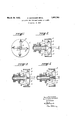
Fig. 1 is an end view of a thread cutting head embodying the distinctive features of the invention;
Figs. 2 and 3 and 4 are longitudinal sections of Fig. 1 at various stages of the cutting operation.
Referring to the drawings in detail, and particularly to Figs. 1 to 4 inclusive, 1 represents a head for holding cutters 2. Conventional means, not shown, are provided for giving head 1 a longitudinal motion. Such means may comprise the usual cam track or eccentric. The cutters 2 slide in tracks 3 which are curved with respect to the longitudinal axis of the head 1. Cutters 2 are connected by links 4 to a collar 5 which is movable with respect to the axis of head 1.
of chuck, and head 1 is rotated. As the point is being formed, head 1 is moved slowly backward, whereby cutters 2 travel toward the front end of tracks 3. In this manner, the cutters are constantly withdrawn radially from the screw blank until their profile lines are substantially parallel to the axis of said blank.
It is to be understood that the profile of the finished screw depends on the configuration of tracks 3 which may be varied as desired.
Having thus described various embodiments of our invention, which embodiments are not to be taken as limitative but rather demonstrative, what is claimed as new and desired to be protected by Letters Patent, is:
In a screw threading apparatus, in combination, a rotary cutter holding head having radial openings and arcuate guideways in the walls thereof, a plurality of cutters mounted in said openings and operatively connected with said guideways, said cutters being provided with profile lines which are supported by said guideways at an angle to the. longitudinal axis of the blank to be threaded at the beginning of the cutting operations, and means for changing the angle of the cutters comprising a link for each cutter connected to the latter at one end, and a collar movable axially of said head and to which the other end of each link is connected.
In testimony whereof we have aflixed our I signatures;
DAVID SWENDSEN. PER LEONARD STENMAN.
Applications Claiming Priority (1)
| Application Number | Priority Date | Filing Date | Title |
|---|---|---|---|
| SE1851783X | 1926-11-23 |
Publications (1)
| Publication Number | Publication Date |
|---|---|
| US1851783A true US1851783A (en) | 1932-03-29 |
Family
ID=20423788
Family Applications (1)
| Application Number | Title | Priority Date | Filing Date |
|---|---|---|---|
| US230705A Expired - Lifetime US1851783A (en) | 1926-11-23 | 1927-11-03 | Apparatus for the manufacture of screws |
Country Status (1)
| Country | Link |
|---|---|
| US (1) | US1851783A (en) |
-
1927
- 1927-11-03 US US230705A patent/US1851783A/en not_active Expired - Lifetime
Similar Documents
| Publication | Publication Date | Title |
|---|---|---|
| US4651374A (en) | Combined hole making and threading tool | |
| US2898612A (en) | Combined drill and tap having drill lands extending throughout the length of the tapping portion | |
| US1851783A (en) | Apparatus for the manufacture of screws | |
| US2389885A (en) | Method and apparatus for straightening blanks | |
| US1618541A (en) | Method of and apparatus for manufacturing chamfered pipe and nipple blanks | |
| US1579888A (en) | Cutting tool | |
| US1556655A (en) | Method of making auger bits | |
| US1309232A (en) | Tool of circular shape with cutting-teeth, such as screw-taps, screw-plates, boring-tools, and milling-cutters. | |
| US1501117A (en) | Tap and cutter | |
| US2145370A (en) | Expansion reamer | |
| US2272200A (en) | Boring or internal forming tool | |
| US2018523A (en) | Forming and milling tool for dies | |
| US1140130A (en) | Milling-cutter. | |
| US1730231A (en) | Expansible reamer | |
| US1332455A (en) | Expansible and contractible tool | |
| US2041027A (en) | Thread cutting mechanism | |
| US2041082A (en) | Thread cutting tool | |
| US2574260A (en) | Die head for cutting threads | |
| US945901A (en) | Screw-cutting attachment. | |
| US972122A (en) | Tool for making ferrules. | |
| US1616542A (en) | Machine for cutting pipe threads | |
| US1239659A (en) | Cutting-tool. | |
| US1100984A (en) | Screw-cutting tap. | |
| US2333156A (en) | Lathe tool | |
| US1257035A (en) | Feed mechanism for bar-stock. |