US1851770A - Clip - Google Patents
Clip Download PDFInfo
- Publication number
- US1851770A US1851770A US457686A US45768630A US1851770A US 1851770 A US1851770 A US 1851770A US 457686 A US457686 A US 457686A US 45768630 A US45768630 A US 45768630A US 1851770 A US1851770 A US 1851770A
- Authority
- US
- United States
- Prior art keywords
- loop
- clip
- shank
- arm
- thence
- Prior art date
- Legal status (The legal status is an assumption and is not a legal conclusion. Google has not performed a legal analysis and makes no representation as to the accuracy of the status listed.)
- Expired - Lifetime
Links
- 210000003813 thumb Anatomy 0.000 description 8
- 210000000078 claw Anatomy 0.000 description 6
- 238000010276 construction Methods 0.000 description 2
- 229910000831 Steel Inorganic materials 0.000 description 1
- 230000004048 modification Effects 0.000 description 1
- 238000012986 modification Methods 0.000 description 1
- 239000010959 steel Substances 0.000 description 1
Images
Classifications
-
- G—PHYSICS
- G09—EDUCATION; CRYPTOGRAPHY; DISPLAY; ADVERTISING; SEALS
- G09F—DISPLAYING; ADVERTISING; SIGNS; LABELS OR NAME-PLATES; SEALS
- G09F1/00—Cardboard or like show-cards of foldable or flexible material
- G09F1/10—Supports or holders for show-cards
-
- Y—GENERAL TAGGING OF NEW TECHNOLOGICAL DEVELOPMENTS; GENERAL TAGGING OF CROSS-SECTIONAL TECHNOLOGIES SPANNING OVER SEVERAL SECTIONS OF THE IPC; TECHNICAL SUBJECTS COVERED BY FORMER USPC CROSS-REFERENCE ART COLLECTIONS [XRACs] AND DIGESTS
- Y10—TECHNICAL SUBJECTS COVERED BY FORMER USPC
- Y10T—TECHNICAL SUBJECTS COVERED BY FORMER US CLASSIFICATION
- Y10T24/00—Buckles, buttons, clasps, etc.
- Y10T24/20—Paper fastener
- Y10T24/202—Resiliently biased
- Y10T24/205—One piece
- Y10T24/206—Mounted on support means
-
- Y—GENERAL TAGGING OF NEW TECHNOLOGICAL DEVELOPMENTS; GENERAL TAGGING OF CROSS-SECTIONAL TECHNOLOGIES SPANNING OVER SEVERAL SECTIONS OF THE IPC; TECHNICAL SUBJECTS COVERED BY FORMER USPC CROSS-REFERENCE ART COLLECTIONS [XRACs] AND DIGESTS
- Y10—TECHNICAL SUBJECTS COVERED BY FORMER USPC
- Y10T—TECHNICAL SUBJECTS COVERED BY FORMER US CLASSIFICATION
- Y10T24/00—Buckles, buttons, clasps, etc.
- Y10T24/46—Pin or separate essential cooperating device therefor
- Y10T24/4602—Pin or separate essential cooperating device therefor with separately operable, manually releasable, nonpenetrating means for mounting [e.g., drapery hook]
Definitions
- This invention relates to a wire clip which is preferably formed for association with the neck part of avacuum cup.
- the clip is very simple and unique in con- 5 struction and the same may be em loyed for many uses by constructing the s ank part of the clip in diflerent shapes.
- the shank part of the clip may be pointed so that it may be pinned to wear ng 1
- the shank may also be formed so as to secure the cli in a depending position on a w re or cor which may bestrung across the mside of a store display window; and further, 'the shank may be constructed in the shape of a large ring or loofiovtvhich will be ada ted to clamp about a can, tle, or the like, w 1c h may be arranged on shelves. If used in thls I latter manner, a price tag may be secured in the clip. Obviously, the shank part of the clip may be constructed in other shapes than those mentioned, to thereby adapt the clip for other purposes.
- One particular object of the invention is to provide a clip having a shank 8601111115 part which is extended to provide a loop, an with a portion folded to engage one side of the loop and thence into a number 'ofturns to 30 provide a movable thumb and arm part, of which the latter is adapted for movement in and out of the loop.
- Fig. 1 illustrates the clip associated w1th a vacuum cup in its normal depending POSI- tion, with said vacuum cup being aflixed to a window pane;
- Fig. 2 1s a side view in elevatlon of the chp and vacuum cup shown in Fig. 1;
- Fi 3 is a pers ective plane view showing the (sip per se, c early s owing the manner in which the clip is bent or twisted.
- the clip device is preferably constructed from a single piece of steel wire and includes 1930. Serial I0. 457,0.
- the wire is further xtended upwardly as at 11 around to provide a thumb art 12 and downwardly substantially paral e1 with the portions 9 and 11, as at 13, and thence bent 05 substantially at right angles to the rtion 13, to thereby provide an arm 14 w ich is adapted to be normally positioned between the sides 3 and 4 of the loo as clearly shown.
- the end of the arm 14 is nt to form a sort 7 of claw 15, which is sharpened to thereby provide means for piercing an advertisement,
- the shank art 1, the declined part 2, and 15 side 3 of t e loop lie substantially in the same plane and that the parts 9, 11 and 13 are twisted at substantially right angles to the shank 1, the bent portions 5 and 8 and the sides of the loops 3 and 4.
- the side portion so 4 of the loopj is constructed to lie in a lane substantially parallel with the side 8, to eraby allow the'loop to lie flat when contacting with a window pane or wall, and also to cause an advertisement which may be secured in the clip to be suspended in a plane substantially parallel with a window pane or wall.
- the shank part 1 of the clip device in its preferred construction is formed with a hook part 15, and a loop 16, the hook art being adapted to engage the head or neck part of a vacuum cupandthe bend or loop 16 adapted to. provide a sort of eye through which a cord or wire may extend.
- the clip may be constructed so as to eliminate the coile spring ortion 10. In fact, the clip has been made in t 's manner and found satisfactory.
- Figs. 1 and 2 the device is shown with. its hook part 15 in engagement with the neck or head 20 of the vacuum cup 21, which is in turn secured to a window pane 22. Obviously, the distance between the planes of the shank 1 and the loop are substantially equal to the hei ht of the vacuum cup.
- a clip formed to provide a loop, and with a part folded to engage a side of the loop and thence into a number of turns to provide a movable thumb part and arm part,
- a clip formed to provide an elongated loop, and with a part folded to engage a side of the loop and thence into a number of turns to provide a coiled spring, and a combined movable thumb part and arm part, of which the latter is adapted for movement in and out of the loop, and said arm part provided with a claw.
- a clip having a shank securing part which is extended to form an offset loop and thence into a number of turns to provide an arm adapted for movement in and out of the loo 5
- a clip having a shank formed to provide a hook securing part, said shank angularly extended to form an elongated loop and thence into a number of turns to provide an arm shorter than the length of the loop adapted for movement in and out of the loop, and said arm provided with a claw to aid in gripping an article:
- a clip having a shank formed to provide a securing part, said part including a hook with a bend extending therefrom, said shank extended in another direction to form a 100 and thence into a number of turns to provi e emme an arm adapted for movement in and out the loop.
- a clip having 211* shank securing part which is extended to form a loop arranged in a plane substantially parallel to the shank part and thence formed at an angle to provide a part adapted to contact the first formed side of the loop, and further formed into a number of turns to rovide an arm adapted for movement in an out of loop.
- a clip having an angularly shaped shank securing part which is extended to form an elongated loop arranged in a plane substantial y parallel to the shank part and thence formed at an angle to provide a closed loop, and further formed into a number of turns to provide a coiled spring and an arm of which the latter alone is adapted for movement to and from the loop.
- a clip having a s ank securing part which is extended to form. a loop arranged in an offset osition in a plane substantially parallel to t e shank part and thence formed to contact and extend beyond the first formed side of the loop, and further formed back upon itself and into a number of turns substantially at ri ht angles to the plane of the loop and Shani part, and thence into the lane of the loop to provide an arm adapted or movement in and out of loop.
- a clip having a loop, and a part extended substantially at right angles to one side of the loop to contact and extend beyond the other side thereof, a part folded back on said first mentioned part and extended at right angles therefrom from the lane formed by the 100 to provide a coile spring, and thence bee in parallel position to provide a thumb part having an arm part at right angles thereto adapted for movement between the sides of the loop, and said arm provided with a claw.
- a clip having a loop, and a part extended substantially at right angles to one side of the loop to contact and extend be ond the other side of the loop, a part folded ack on said first mentioned part, a part extending from. the plane formed b the loop and thence back to provide a thum part having an integral arm part adapted for movement between the sides of t e loop, and said arm provided with a claw.
- a clip having a shank formed to provide a securing part, said part including a hook with a hen extending therefrom, said shank extended in another direction to form a loop, and thence into a number of turns to provide a thumb part, and an arm part, the latter being adapted for movement in and out of the 1001p.
- a c ip having a shank formed to provide a securing part, said part including a hook with a bend extending transversely of the plane formed by the hook, said shank extended in another direction to provide an offset 100 and thence into a. number of turns to provi e an arm part adapted for movement relative the loop.
- a clip having a shank formed to provide a securing part, said part including a hook with a bend extended therefrom, said shank extended in another direction to form a loop, and thence into a number of turns to provide an arm adapted for movement relative the loop.
Landscapes
- Physics & Mathematics (AREA)
- General Physics & Mathematics (AREA)
- Engineering & Computer Science (AREA)
- Theoretical Computer Science (AREA)
- Supports Or Holders For Household Use (AREA)
Description
March 29, 1932 f BJJHNSQN 1,851,770
a CLIP Filed May 31, 1930 wwz Patented Mar. 29, 1932 UNITED STATES PATENT OFFICE Application fled Kay 81,
This invention relates to a wire clip which is preferably formed for association with the neck part of avacuum cup.
The clip is very simple and unique in con- 5 struction and the same may be em loyed for many uses by constructing the s ank part of the clip in diflerent shapes. For an example, the shank part of the clip may be pointed so that it may be pinned to wear ng 1| apparel, suchas dresses, coats, and the like, which may be suspended in tiers on racks. The shank may also be formed so as to secure the cli in a depending position on a w re or cor which may bestrung across the mside of a store display window; and further, 'the shank may be constructed in the shape of a large ring or loofiovtvhich will be ada ted to clamp about a can, tle, or the like, w 1c h may be arranged on shelves. If used in thls I latter manner, a price tag may be secured in the clip. Obviously, the shank part of the clip may be constructed in other shapes than those mentioned, to thereby adapt the clip for other purposes.
One particular object of the invention is to provide a clip having a shank 8601111115 part which is extended to provide a loop, an with a portion folded to engage one side of the loop and thence into a number 'ofturns to 30 provide a movable thumb and arm part, of which the latter is adapted for movement in and out of the loop. 0
Other objects and advantages of the improved type of clip will be ObVlOllS after readin the detailed description in connection with tfie drawings forming a part hereof.
In the drawings, wherein like reference characters indicate like or corresponding parts of the clip:
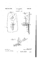
Fig. 1 illustrates the clip associated w1th a vacuum cup in its normal depending POSI- tion, with said vacuum cup being aflixed to a window pane;
Fig. 2 1s a side view in elevatlon of the chp and vacuum cup shown in Fig. 1; and
Fi 3 is a pers ective plane view showing the (sip per se, c early s owing the manner in which the clip is bent or twisted.
The clip device is preferably constructed from a single piece of steel wire and includes 1930. Serial I0. 457,0.
a shank portion 1, a declined rtion 2, a 100 having substantially paralle sides 3 and :a part 5 bent substantially at right angles to as indicated at 8, and thence bent upwardly as at 9 substantially at right angles to the por- 00 tion 8, and twisted to form a coiled spring 10. The wire is further xtended upwardly as at 11 around to provide a thumb art 12 and downwardly substantially paral e1 with the portions 9 and 11, as at 13, and thence bent 05 substantially at right angles to the rtion 13, to thereby provide an arm 14 w ich is adapted to be normally positioned between the sides 3 and 4 of the loo as clearly shown. The end of the arm 14 is nt to form a sort 7 of claw 15, which is sharpened to thereby provide means for piercing an advertisement,
or other article adapted to be secured thereby.
It will be apparent from the drawings, that the shank art 1, the declined part 2, and 15 side 3 of t e loop lie substantially in the same plane and that the parts 9, 11 and 13 are twisted at substantially right angles to the shank 1, the bent portions 5 and 8 and the sides of the loops 3 and 4. The side portion so 4 of the loopjis constructed to lie in a lane substantially parallel with the side 8, to eraby allow the'loop to lie flat when contacting with a window pane or wall, and also to cause an advertisement which may be secured in the clip to be suspended in a plane substantially parallel with a window pane or wall.
The shank part 1 of the clip device in its preferred construction is formed with a hook part 15, and a loop 16, the hook art being adapted to engage the head or neck part of a vacuum cupandthe bend or loop 16 adapted to. provide a sort of eye through which a cord or wire may extend.
Obviously the clip ma be constructed so as to eliminate the coile spring ortion 10. In fact, the clip has been made in t 's manner and found satisfactory.
In Figs. 1 and 2, the device is shown with. its hook part 15 in engagement with the neck or head 20 of the vacuum cup 21, which is in turn secured to a window pane 22. Obviously, the distance between the planes of the shank 1 and the loop are substantially equal to the hei ht of the vacuum cup.
To 0 rate e device, it will be evident that it is only.necessary to pull back on the movable thumb part to position it as shown by the dotted lines in Fig. 2, and thence insert a print 23, magazine, or other article between the loop and arm, and then release the arm to thereby secure the rint with the shar ned claw of the arm being adapted to per orate the article.
Having thus described my invention it is obvious that various immaterial modifications may be made in the same without dearting from the spirit of my invention;
ence, do not wish to be understood as limiting myself to the exact form, construction, arrangement and combination of parts herein shown and described or uses mentioned.
What I claim as new and desire to secure by Letters Patent is:
1. A clip formed to provide a loop, and with a part folded to engage a side of the loop and thence into a number of turns to provide a movable thumb part and arm part,
of which the latter is adapted for movement in and out of the loop.
2. A clip formed to rovide an elongated loop, and with a part olded at right angles to engage and extend beyond a side of the loop and back upon itself, and thence at right angles into a number of turns to provide a combined movable thumb part and arm part, of which the latter is adapted for movement in and out of the loop.
3. A clip formed to provide an elongated loop, and with a part folded to engage a side of the loop and thence into a number of turns to provide a coiled spring, and a combined movable thumb part and arm part, of which the latter is adapted for movement in and out of the loop, and said arm part provided with a claw.
4. A clip having a shank securing part which is extended to form an offset loop and thence into a number of turns to provide an arm adapted for movement in and out of the loo 5 A clip having a shank formed to provide a hook securing part, said shank angularly extended to form an elongated loop and thence into a number of turns to provide an arm shorter than the length of the loop adapted for movement in and out of the loop, and said arm provided with a claw to aid in gripping an article:
6. A clip having a shank formed to provide a securing part, said part including a hook with a bend extending therefrom, said shank extended in another direction to form a 100 and thence into a number of turns to provi e emme an arm adapted for movement in and out the loop.
7. A clip having 211* shank securing part which is extended to form a loop arranged in a plane substantially parallel to the shank part and thence formed at an angle to provide a part adapted to contact the first formed side of the loop, and further formed into a number of turns to rovide an arm adapted for movement in an out of loop.
8. A clip having an angularly shaped shank securing part which is extended to form an elongated loop arranged in a plane substantial y parallel to the shank part and thence formed at an angle to provide a closed loop, and further formed into a number of turns to provide a coiled spring and an arm of which the latter alone is adapted for movement to and from the loop.
9. A clip having a s ank securing part which is extended to form. a loop arranged in an offset osition in a plane substantially parallel to t e shank part and thence formed to contact and extend beyond the first formed side of the loop, and further formed back upon itself and into a number of turns substantially at ri ht angles to the plane of the loop and Shani part, and thence into the lane of the loop to provide an arm adapted or movement in and out of loop.
10. A clip having a loop, and a part extended substantially at right angles to one side of the loop to contact and extend beyond the other side thereof, a part folded back on said first mentioned part and extended at right angles therefrom from the lane formed by the 100 to provide a coile spring, and thence bee in parallel position to provide a thumb part having an arm part at right angles thereto adapted for movement between the sides of the loop, and said arm provided with a claw.
11. A clip having a loop, and a part extended substantially at right angles to one side of the loop to contact and extend be ond the other side of the loop, a part folded ack on said first mentioned part, a part extending from. the plane formed b the loop and thence back to provide a thum part having an integral arm part adapted for movement between the sides of t e loop, and said arm provided with a claw.
12. A clip having a shank formed to provide a securing part, said part including a hook with a hen extending therefrom, said shank extended in another direction to form a loop, and thence into a number of turns to provide a thumb part, and an arm part, the latter being adapted for movement in and out of the 1001p.
13. A c ip having a shank formed to provide a securing part, said part including a hook with a bend extending transversely of the plane formed by the hook, said shank extended in another direction to provide an offset 100 and thence into a. number of turns to provi e an arm part adapted for movement relative the loop.
14. A clip having a shank formed to provide a securing part, said part including a hook with a bend extended therefrom, said shank extended in another direction to form a loop, and thence into a number of turns to provide an arm adapted for movement relative the loop.
In witness whereof I hereunto subscribe my name this 19th day of Ma A. D. 1930.
EDWIN JOHNSON.
Priority Applications (1)
| Application Number | Priority Date | Filing Date | Title |
|---|---|---|---|
| US457686A US1851770A (en) | 1930-05-31 | 1930-05-31 | Clip |
Applications Claiming Priority (1)
| Application Number | Priority Date | Filing Date | Title |
|---|---|---|---|
| US457686A US1851770A (en) | 1930-05-31 | 1930-05-31 | Clip |
Publications (1)
| Publication Number | Publication Date |
|---|---|
| US1851770A true US1851770A (en) | 1932-03-29 |
Family
ID=23817735
Family Applications (1)
| Application Number | Title | Priority Date | Filing Date |
|---|---|---|---|
| US457686A Expired - Lifetime US1851770A (en) | 1930-05-31 | 1930-05-31 | Clip |
Country Status (1)
| Country | Link |
|---|---|
| US (1) | US1851770A (en) |
Cited By (9)
| Publication number | Priority date | Publication date | Assignee | Title |
|---|---|---|---|---|
| US2629575A (en) * | 1949-11-10 | 1953-02-24 | Clara D Loyot | Clothes hanger attachment |
| US2882856A (en) * | 1955-07-27 | 1959-04-21 | Victor P Drury | Directive devices for motorists |
| US2972377A (en) * | 1960-02-29 | 1961-02-21 | Edwin N Jacobs | Rain visor for automobile windshield |
| US3011649A (en) * | 1960-08-25 | 1961-12-05 | Porter Robert Bruce | Holder for cigarette package |
| US4150860A (en) * | 1976-09-10 | 1979-04-24 | Ducasse Joseph C V | Filing system for vertically supporting documents |
| US4180182A (en) * | 1976-11-23 | 1979-12-25 | Bank Computer Network Corporation | Dispensing magazine |
| US4703569A (en) * | 1986-06-25 | 1987-11-03 | David Bowman | Poster mounting system |
| US4903379A (en) * | 1988-06-16 | 1990-02-27 | Uchtman Charles C | Pin and clip arrangement for name tags and badges |
| US20120112024A1 (en) * | 2009-07-01 | 2012-05-10 | Gotzl Werner | Clamp holder for attaching a display means to a base |
-
1930
- 1930-05-31 US US457686A patent/US1851770A/en not_active Expired - Lifetime
Cited By (9)
| Publication number | Priority date | Publication date | Assignee | Title |
|---|---|---|---|---|
| US2629575A (en) * | 1949-11-10 | 1953-02-24 | Clara D Loyot | Clothes hanger attachment |
| US2882856A (en) * | 1955-07-27 | 1959-04-21 | Victor P Drury | Directive devices for motorists |
| US2972377A (en) * | 1960-02-29 | 1961-02-21 | Edwin N Jacobs | Rain visor for automobile windshield |
| US3011649A (en) * | 1960-08-25 | 1961-12-05 | Porter Robert Bruce | Holder for cigarette package |
| US4150860A (en) * | 1976-09-10 | 1979-04-24 | Ducasse Joseph C V | Filing system for vertically supporting documents |
| US4180182A (en) * | 1976-11-23 | 1979-12-25 | Bank Computer Network Corporation | Dispensing magazine |
| US4703569A (en) * | 1986-06-25 | 1987-11-03 | David Bowman | Poster mounting system |
| US4903379A (en) * | 1988-06-16 | 1990-02-27 | Uchtman Charles C | Pin and clip arrangement for name tags and badges |
| US20120112024A1 (en) * | 2009-07-01 | 2012-05-10 | Gotzl Werner | Clamp holder for attaching a display means to a base |
Similar Documents
| Publication | Publication Date | Title |
|---|---|---|
| US1851770A (en) | Clip | |
| GB1162788A (en) | Fastening and Locking Device | |
| US1990128A (en) | Garment hanger | |
| US1863544A (en) | Attachment for fishhooks | |
| US2108678A (en) | Hat hanger | |
| US2756478A (en) | Fishline connector joint | |
| US2122309A (en) | Garment hanger | |
| US1806477A (en) | Attaching device for bait boxes | |
| US3975856A (en) | Releasable fishing hook | |
| US745131A (en) | Fish-hook-attaching device. | |
| US2353839A (en) | Shoulder tree | |
| US1323394A (en) | Live-bait hook | |
| US2342017A (en) | Flag or similar mounting for aerials | |
| US2464880A (en) | Fishing pole attachment | |
| US2174955A (en) | Plant support | |
| US2004316A (en) | Fishhook | |
| US2149062A (en) | Fishhook | |
| US2021730A (en) | Clip member | |
| US1453502A (en) | Hook | |
| US2196118A (en) | Necktie rack | |
| US1372225A (en) | Price-tag holder | |
| US1030729A (en) | Corn-holder. | |
| US2218046A (en) | Fishhook | |
| US2338213A (en) | Garment hanger | |
| US2288357A (en) | Wire bottle carrier |