US1851755A - Can testing machine - Google Patents
Can testing machine Download PDFInfo
- Publication number
- US1851755A US1851755A US543289A US54328931A US1851755A US 1851755 A US1851755 A US 1851755A US 543289 A US543289 A US 543289A US 54328931 A US54328931 A US 54328931A US 1851755 A US1851755 A US 1851755A
- Authority
- US
- United States
- Prior art keywords
- valve
- machine
- diaphragm
- testing
- air
- Prior art date
- Legal status (The legal status is an assumption and is not a legal conclusion. Google has not performed a legal analysis and makes no representation as to the accuracy of the status listed.)
- Expired - Lifetime
Links
Images

Classifications
-
- G—PHYSICS
- G01—MEASURING; TESTING
- G01M—TESTING STATIC OR DYNAMIC BALANCE OF MACHINES OR STRUCTURES; TESTING OF STRUCTURES OR APPARATUS, NOT OTHERWISE PROVIDED FOR
- G01M3/00—Investigating fluid-tightness of structures
- G01M3/02—Investigating fluid-tightness of structures by using fluid or vacuum
- G01M3/26—Investigating fluid-tightness of structures by using fluid or vacuum by measuring rate of loss or gain of fluid, e.g. by pressure-responsive devices, by flow detectors
- G01M3/32—Investigating fluid-tightness of structures by using fluid or vacuum by measuring rate of loss or gain of fluid, e.g. by pressure-responsive devices, by flow detectors for containers, e.g. radiators
- G01M3/3236—Investigating fluid-tightness of structures by using fluid or vacuum by measuring rate of loss or gain of fluid, e.g. by pressure-responsive devices, by flow detectors for containers, e.g. radiators by monitoring the interior space of the containers
- G01M3/3263—Investigating fluid-tightness of structures by using fluid or vacuum by measuring rate of loss or gain of fluid, e.g. by pressure-responsive devices, by flow detectors for containers, e.g. radiators by monitoring the interior space of the containers using a differential pressure detector
Definitions
- This invention relates to machines for testing sheet metal cans or s imilar receptacles and for discarding or discharging leaky cans.
- the object of the present the superior pressure and then its displacement acts to operate a tripping mechanism the travel of the cans the defective cans are whereby at the end of through the machine,
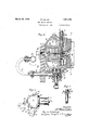
- Fig. 2 is a of the units in a radial turntable of the machine; diametrical section through one plane coincident with the axis of rotation of the turntable;
- Fig. 3 is a sectional elevation showing two of the units, that at the left on the plane of the line 3, and that at the right on the plane of the line 8 in Fig. 2;
- Fig. 4 is a section on the plane of the line 4 i inFig. 3;
- Figs. 5 and 6 are sect ions'and elevations of the opposite side
- Fig. 7 is an elevation of the movable member of the valve.
- Fig. is a diagram illustrating the circuit connections.
- the various can testing elements are carried by the rotary disk Ewhich is mounted to turn on a suitable shaft or stud carried by fixed framework and having gearing for revolving it.
- a corresponding disk or turntable E is shown, and there is also shown a fixed cam piece or ring F.
- the testing units A, A are carried on the turntable E, which also carries apipe B which is fed with compressed air. From this pipe branches C, O lead to valve shells ,1), one for each unit, by which the compressed air is fed to the individual units.
- Each consists of a casing G suitably fastened to the turntable E and having a flat face covered by a gasketH of suitably yielding material, such as rubber, against which the can to be tested is pressed by a pad or plunger J, as shown in Fig. 1, this being operated by any known mechanism,-such, for example, as the means shown in-the aforesaid patent, where the pad is marked m, m,auto-. matic means being provided for moving the pad into position to press the can against the gasket. in the entering position and for retractingit to release the can in the final discharging position; as these mechanisms are well known, it is not thought necessary to illustrate them here.
- the casing G is formed hollow to constitute a chamber K, within which is located a shell L-formin the base of a multiple diaphragm M of t e bellows type commonly called a sylphon ;-the opposite ends of this diaphragm are hermetically secured to the inner end of this shell and to a disk N, on which is fastened a center pin or stud O, the outer end of which, projecting beyond the disk, serves as a contact stud or button which, as the diaphragm expands or contracts, moves into or out of contact with an adjustable contact screw P which is accessible for purposes of adjustment through the central opening of a flanged thimble Q which serves for fastening the gasket H to the flat outer face or head R of the unit.
- adjusting screw P To afford the adjusting screw P an insulating support, it is engaged in the threaded hub of a metal disk S which is fastened on a disk or cap T of insulating material, such as vulcanized fiber, which is seated in a ring U or other convenient fitting of metal, which in turn is seated in the casing G.
- insulating material such as vulcanized fiber
- a contact button V which is insulated from the shell and electrically connected to the contact screw P. It is shown as having a shank which is carried through an insulating bushing W, from'which a conducting pin Y extends through openings in the ring U and insulating disk T to a metallic connection with the disk S into which the screw P is threaded.
- the rotation of the turntable carries the unit to a point toward the end of the testing period, where the button V touches a circuit terminal c'in circuitd fed by battery 6 and containing a solenoid 7 connected to the operating arm 9 of a gate it suitably located to drop the defective can out of the machine,--as, for example, by rolling it down a chute indicated in dotted lines at iall as shown diagrammatically in Fig. 8.
- This electrically operating ejecting means forms no part of the present invention and is illustrated only as one example of how the unit provided by the present invention may be applied in connection with suitable ejecting mechanism.
- the unit A includes a twin valve for admitting compressed air from the pipe B into the can to be tested and into the chamber K which communicates with the interior of the diaphragm M.
- the valve comprises a stationary seat and a movable tappet 7a which is conveniently mounted on a stem m passing out through the bottom opening in the valve shell D, where it is connected with.
- the leverp is fulcrumed on a'bracket g projecting from the shellD and carries a roller 1 which is engaged by the cam F (Fig.- 3) at a point in the travel of the unit directly after the can has been placed in position.
- the cam operation lowers the stem m and tappet 7.", whereby to admit compressed air through the valve seat openings sandt.
- the opening .9 communicates with the chamber K, and the opening I? communicates through a port with the interior of the can and equally with the exterior of the diaphragm M,that is to say, with a chamber Z formed around the diaphragmand between it and the shell L. WVhile the valve construction may be greatly varied, that shown in de tail has certain practical advantages.
- the seat openings 8 and t are formed through tubes or bushings seated in the casing G and project through openings in a gasket or packing ring u (shown separately in Fi 5) which is held in place by a retaining disk '0 (shown separately in Fig. 6).
- the tapper 1 0 is shown as carrying two annular flanges 'w, 10 which are concentric with and enclose the projecting ends of the seat nipples. WVhen the tappet is lowered to the position shown in Fig. 2 by the action of the cam F, the compressed air flows through openings a: in the tapper and flows around the ends of the flanges w and into the respective nipples and their passages s, 25. Thus the air is admitted at equal pressures to the chamber K and to the chamber Z and the interior of the can.
- Each unit A comprising the casing G and its attached parts and contents, together with the valve and its lever p, is a complete operative entity andmay be separately removed from the machine. To remove it, itis only neces sary to disconnect a coupling 10 connecting the two sections of the pipe C and toremove the fastening screws 12, whereupon the unit may be taken off from the turntable E and another like unit substituted. This affords a very convenient way of correcting the machine when any unit gets out of repair or adj ustment. As each unit carries its own valve, so that the valve is removed with the unit, the separate testing of the valve is facilitated.
- valve construction is such as to afford a thoroughly tight closure, whereby the leaklong use, it is only necessary to remove the valve shell D and replacethe packing gasket u. z
- the mechanical construction of the machine is simplified because the valve requires operative means only at one point in the rotation of the turntable, and this consists of the simple stationary cam F. Since the testing units are all alike and are so con-' structed as to favor their production in quantities, the machine is thereby cheapened.
- the use of the compound or bellows form of diaphragm M results in a greatly increased amplitude of motion for a given change in internal pressure, whereby its operation is made more positive and certain.
- the present machine has no exhaust valve or exhaust air conduit.
- a practically desirable feature is the introduction in each branch pipe C of a choke gasket 2, being a disk with a small hole for holding back any rush of air when the valve is opened. This enables the use of compressed air with much higher pressure than has heretofore been practicable.
- the choke gasket may serve also as a packing between the two members of the coupling 10.
- the size of the orifice in'the choke gasket is necessarily determined by experiment, since it varies with the pressure in the supply conduit B, also to some extent with the capacity of the can to be tested and the rapidity with which the machine is to operate. Cans for some purposes require to be more thoroughly tested against leakage than others, and the machine may be adapted for these variations by varying its speed, by varying the pressure in the air conduit, and by suitably graduating the size of the choke orifice.
- the choke orifice enables adjustments to be made for the effect of temperature variation; it, is known that the sudden admission of compressed air into a can raises the temperature therein, which may establish a temperature difference between the chambers on opposite sides of the diaphragm,a condition which in the past has sometimes created difficulty in the adjustment of the testing elements; but with the choke orifice, the drop of pressure on passing this orifice lowers the temperature and this may approximately compensate for the raise of temperature occurring when the air enters the can.
- the retardation of the flow of air by the choke orifice is also of advantage, in that it enables the air valve to be opened somewhat in advance of the usual practice, whereby to discharge any surplus pressure from the chamber K and (create a better initial equalization of pressures on opposite sides of the diaphragm.
- the machine maybe constructed for operation either with compressed air or with rarefied air or vacuum.
- the type of machine to which the present invention is directed and upon which itis an improvement comprises an endless carrier with means for advancing it continuously or intermittently, with a series of testing units carried thereby, each unit adapted to receive a can to be tested and enclosing two chambers, one of which is in communication with the interior of the can under test, and a movable part such as a diaphragm interposed between such chambers, with a, valve or valves receiving air under pressure opened to admit the same under equal pressureto both chambers at the beginning of the testing period and thereupon closed and held closed during the testing period, and With a can discharge controlled by the mechanism in the nature ofa trip device which is operated under control of said movable part or diaphragm, so that in case of diminution of pressure on the side of the latter communicating with the interior of the can, the latter on being released at the end of testing period, is discharged through a different outlet from that receiving the delivery of normal cans.
- a trip device which is operated under control of said movable part or
- the respective testing units each comprising a hollow casing forming a chamber, a shell within such chamber, a bellows diaphragm Within such shell, and relatively movable electric contacts, one of the contacts connected to the diaphragm, whereby an electric circuit is controlled by the movement of the diaphragm.
- a can testing machine of the described type each comprising a hollow casing forming a chamber, a diaphragm within such casing, its one side communicating with said chamber and its other side communicating with the interior of the can under test, a valve shell having separate ports communicating with the chambers on opposite sides of the diaphragm, and a valve in said shell movable to simultaneously open or close said ports.
- valve and its seat comprising annular portions and a gasket at the admission to the respective ports.
- valve being a twin valve having separate seating portions to close both ports.
Landscapes
- Physics & Mathematics (AREA)
- General Physics & Mathematics (AREA)
- Examining Or Testing Airtightness (AREA)
Description
March 29, w D|ETER CAN- TESTING MACHINE 2 Sheets-Sheet 1 Filed June 10, 1931 I I I I I March 9 w. DIETER CAN TESTING MACHINE Filed June 10, 1951 2 Sheets-Sheet 2 @mafb m UNITED. STATES PATENT OFFICE- WILLIAM DIETER, or. NEWARK, NEW JERSEY Application filed June 10,
CAN TESTING MACHINE This invention relates to machines for testing sheet metal cans or s imilar receptacles and for discarding or discharging leaky cans.
- An example of a machine for this purpose 5 is contained in the patent to Peter Kruse, No. 779,719, dated January 10, 1905. In such machines the cans to be tested are fed in succession to the machine and carried around in a rotary path. Each can is pressed against a yielding gasket, and
can and troduced to the which is a movable partition compressed air is into a chamber between such as a ma phragm; the test is continued for a suitable )6110d, and if during this time an interior leakage occurs from the can, the pressure on that side of the diaphragm is diminished and the diaphragm is consequently displaced by the normal delivery outlet.
The object of the present the superior pressure and then its displacement acts to operate a tripping mechanism the travel of the cans the defective cans are whereby at the end of through the machine,
automatically ejected through a discharge chute or into a receptacle while the perfect cans are discharged through invention is to provide an improved construction applicable to machines for this make the operation of tive and positive ject is as possible. I to cheapen the machine and construct 1t purpose, whereby to the machine as sensi- A further 0b-- with individual testing units, any one of which, if it and replaced without r others.
becomes defective, can be removed interfering with the In the accompanying drawings- Figure 1 is an elevati on of one of the units,
showing it applied upon a fragment of the rotary frame or Fig. 2 is a of the units in a radial turntable of the machine; diametrical section through one plane coincident with the axis of rotation of the turntable;
Fig. 3 is a sectional elevation showing two of the units, that at the left on the plane of the line 3, and that at the right on the plane of the line 8 in Fig. 2;
Fig. 4 is a section on the plane of the line 4 i inFig. 3;
. Figs. 5 and 6 are sect ions'and elevations of the opposite side,
1931. Serial No. 543,289.
disks forming part of the air-controlled valve;
Fig. 7 is an elevation of the movable member of the valve; and
Fig. is a diagram illustrating the circuit connections.
In the drawings no attempt is made to show I the general structure of the machine, which is well known.
Referring, for example, to the aforesaid patent, the various can testing elements are carried by the rotary disk Ewhich is mounted to turn on a suitable shaft or stud carried by fixed framework and having gearing for revolving it. In the accompanying drawings a corresponding disk or turntable E is shown, and there is also shown a fixed cam piece or ring F. The testing units A, A are carried on the turntable E, which also carries apipe B which is fed with compressed air. From this pipe branches C, O lead to valve shells ,1), one for each unit, by which the compressed air is fed to the individual units.
The description of one unit will serve for all, since they are duplicates of one another. Each consists of a casing G suitably fastened to the turntable E and having a flat face covered by a gasketH of suitably yielding material, such as rubber, against which the can to be tested is pressed by a pad or plunger J, as shown in Fig. 1, this being operated by any known mechanism,-such, for example, as the means shown in-the aforesaid patent, where the pad is marked m, m,auto-. matic means being provided for moving the pad into position to press the can against the gasket. in the entering position and for retractingit to release the can in the final discharging position; as these mechanisms are well known, it is not thought necessary to illustrate them here.
The casing G is formed hollow to constitute a chamber K, within which is located a shell L-formin the base of a multiple diaphragm M of t e bellows type commonly called a sylphon ;-the opposite ends of this diaphragm are hermetically secured to the inner end of this shell and to a disk N, on which is fastened a center pin or stud O, the outer end of which, projecting beyond the disk, serves as a contact stud or button which, as the diaphragm expands or contracts, moves into or out of contact with an adjustable contact screw P which is accessible for purposes of adjustment through the central opening of a flanged thimble Q which serves for fastening the gasket H to the flat outer face or head R of the unit. To afford the adjusting screw P an insulating support, it is engaged in the threaded hub of a metal disk S which is fastened on a disk or cap T of insulating material, such as vulcanized fiber, which is seated in a ring U or other convenient fitting of metal, which in turn is seated in the casing G.
On the exterior of the unit is mounted a contact button V which is insulated from the shell and electrically connected to the contact screw P. It is shown as having a shank which is carried through an insulating bushing W, from'which a conducting pin Y extends through openings in the ring U and insulating disk T to a metallic connection with the disk S into which the screw P is threaded. In operation the rotation of the turntable carries the unit to a point toward the end of the testing period, where the button V touches a circuit terminal c'in circuitd fed by battery 6 and containing a solenoid 7 connected to the operating arm 9 of a gate it suitably located to drop the defective can out of the machine,--as, for example, by rolling it down a chute indicated in dotted lines at iall as shown diagrammatically in Fig. 8. This electrically operating ejecting means forms no part of the present invention and is illustrated only as one example of how the unit provided by the present invention may be applied in connection with suitable ejecting mechanism.
The unit A includes a twin valve for admitting compressed air from the pipe B into the can to be tested and into the chamber K which communicates with the interior of the diaphragm M. The valve comprises a stationary seat and a movable tappet 7a which is conveniently mounted on a stem m passing out through the bottom opening in the valve shell D, where it is connected with. a lever p for operating it. The leverp is fulcrumed on a'bracket g projecting from the shellD and carries a roller 1 which is engaged by the cam F (Fig.- 3) at a point in the travel of the unit directly after the can has been placed in position. The cam operation lowers the stem m and tappet 7.", whereby to admit compressed air through the valve seat openings sandt. The opening .9 communicates with the chamber K, and the opening I? communicates through a port with the interior of the can and equally with the exterior of the diaphragm M,that is to say, with a chamber Z formed around the diaphragmand between it and the shell L. WVhile the valve construction may be greatly varied, that shown in de tail has certain practical advantages. The seat openings 8 and t are formed through tubes or bushings seated in the casing G and project through openings in a gasket or packing ring u (shown separately in Fi 5) which is held in place by a retaining disk '0 (shown separately in Fig. 6). The tapper 1 0 is shown as carrying two annular flanges 'w, 10 which are concentric with and enclose the projecting ends of the seat nipples. WVhen the tappet is lowered to the position shown in Fig. 2 by the action of the cam F, the compressed air flows through openings a: in the tapper and flows around the ends of the flanges w and into the respective nipples and their passages s, 25. Thus the air is admitted at equal pressures to the chamber K and to the chamber Z and the interior of the can. On passing the cam F the valve is pressed to its seat by a stiff spring y, so that the valve flanges 10 are pressed firmly against the soft gasket u, thereby sealing the air in the respective chambers. If the can is tight, the air remains under this equal pressure in both chambers during the entire test period. If, however, there is a leak from the can, the air within it and in the chamber Z is diminished in pressure, whereby the preponderating pressure within the diaphragm forces the pin 0 toward the right in Fig. 2 until it touches the contact screw P and thereby closes circuit connection with the terminal button V; thereupon, when this button makes contact with the stationary circuit terminal 0, the current flows through the solenoid and the ejector flap H is opened, so that the can upon its mechanical release by the plunger J, which is operated by the usual mechanism, is rolled out down the chute 2'.
The construction herein set forth has cer tain important practical advantages. Each unit A, comprising the casing G and its attached parts and contents, together with the valve and its lever p, is a complete operative entity andmay be separately removed from the machine. To remove it, itis only neces sary to disconnect a coupling 10 connecting the two sections of the pipe C and toremove the fastening screws 12, whereupon the unit may be taken off from the turntable E and another like unit substituted. This affords a very convenient way of correcting the machine when any unit gets out of repair or adj ustment. As each unit carries its own valve, so that the valve is removed with the unit, the separate testing of the valve is facilitated. The valve construction is such as to afford a thoroughly tight closure, whereby the leaklong use, it is only necessary to remove the valve shell D and replacethe packing gasket u. z The mechanical construction of the machine is simplified because the valve requires operative means only at one point in the rotation of the turntable, and this consists of the simple stationary cam F. Since the testing units are all alike and are so con-' structed as to favor their production in quantities, the machine is thereby cheapened. The use of the compound or bellows form of diaphragm M results in a greatly increased amplitude of motion for a given change in internal pressure, whereby its operation is made more positive and certain.
The present machine has no exhaust valve or exhaust air conduit. The residual air which remains in the chamber Z and the communicating passages leading thence through the gasket H to the interior of the can, escapes upon the release of the can and serves a useful function in forcibly separating the can from a possible adhesion to the gasket H. The air communicating with the interior of the diaphragm, including that in the chamber K, is imprisoned and thereby conserved.
A practically desirable feature is the introduction in each branch pipe C of a choke gasket 2, being a disk with a small hole for holding back any rush of air when the valve is opened. This enables the use of compressed air with much higher pressure than has heretofore been practicable. The choke gasket may serve also as a packing between the two members of the coupling 10.
The size of the orifice in'the choke gasket is necessarily determined by experiment, since it varies with the pressure in the supply conduit B, also to some extent with the capacity of the can to be tested and the rapidity with which the machine is to operate. Cans for some purposes require to be more thoroughly tested against leakage than others, and the machine may be adapted for these variations by varying its speed, by varying the pressure in the air conduit, and by suitably graduating the size of the choke orifice. Another advantage of the choke orifice is that it enables adjustments to be made for the effect of temperature variation; it, is known that the sudden admission of compressed air into a can raises the temperature therein, which may establish a temperature difference between the chambers on opposite sides of the diaphragm,a condition which in the past has sometimes created difficulty in the adjustment of the testing elements; but with the choke orifice, the drop of pressure on passing this orifice lowers the temperature and this may approximately compensate for the raise of temperature occurring when the air enters the can. The retardation of the flow of air by the choke orifice is also of advantage, in that it enables the air valve to be opened somewhat in advance of the usual practice, whereby to discharge any surplus pressure from the chamber K and (create a better initial equalization of pressures on opposite sides of the diaphragm.
' It is, of course, to be understood that, the machine maybe constructed for operation either with compressed air or with rarefied air or vacuum.
It is to be understood that the type of machine to which the present invention is directed and upon which itis an improvement, comprises an endless carrier with means for advancing it continuously or intermittently, with a series of testing units carried thereby, each unit adapted to receive a can to be tested and enclosing two chambers, one of which is in communication with the interior of the can under test, and a movable part such as a diaphragm interposed between such chambers, with a, valve or valves receiving air under pressure opened to admit the same under equal pressureto both chambers at the beginning of the testing period and thereupon closed and held closed during the testing period, and With a can discharge controlled by the mechanism in the nature ofa trip device which is operated under control of said movable part or diaphragm, so that in case of diminution of pressure on the side of the latter communicating with the interior of the can, the latter on being released at the end of testing period, is discharged through a different outlet from that receiving the delivery of normal cans.
What I claim is:
1. In a can testing machine of the described type, the respective testing units each comprising a hollow casing forming a chamber, a shell within such chamber, a bellows diaphragm Within such shell, and relatively movable electric contacts, one of the contacts connected to the diaphragm, whereby an electric circuit is controlled by the movement of the diaphragm.
2. A can testing machine of the described type, the respective testing units each comprising a hollow casing forming a chamber, a diaphragm within such casing, its one side communicating with said chamber and its other side communicating with the interior of the can under test,a valve shell having separate ports communicating with the chambers on opposite sides of the diaphragm, and a valve in said shell movable to simultaneously open or close said ports.
3. The structure of claim 2, the valve and its seat comprising annular portions and a gasket at the admission to the respective ports.
4. The structure of claim 2, with a spring for closing the valve and means for opening the valve against the stress of such sprin 5. The structure of claim 2, with a spring for closing the valve and means for opening the valve against the stress of such spring, comprising a lever carried by the unit exteriorly of said valve shell and adaptedto be 6. The structure of claim 2, combined with a compressed air pipe carried by the rotary member of the machine and branches therefrom to the valve shells of the respective units.
7. The structure of claim 2, combined with an annular compressed air pipe carried by the revolving carrier of the machine with branch pipes therefrom leading to the valve shells of the respective units 8. The structure of claim 2, combined with a compressed air pipe carried by the revolving carrier of the machine with branch pipes therefrom leading to the valve shells of the respective units, and a choke in each such branch adapted to drop the pressure of the infiowing air.
9. The structure of claim 2, the valve being a twin valve having separate seating portions to close both ports.
In witness \vhereof,-I have hereunto signed my name.
. WVILLIAM DIETERL
Priority Applications (1)
| Application Number | Priority Date | Filing Date | Title |
|---|---|---|---|
| US543289A US1851755A (en) | 1931-06-10 | 1931-06-10 | Can testing machine |
Applications Claiming Priority (1)
| Application Number | Priority Date | Filing Date | Title |
|---|---|---|---|
| US543289A US1851755A (en) | 1931-06-10 | 1931-06-10 | Can testing machine |
Publications (1)
| Publication Number | Publication Date |
|---|---|
| US1851755A true US1851755A (en) | 1932-03-29 |
Family
ID=24167371
Family Applications (1)
| Application Number | Title | Priority Date | Filing Date |
|---|---|---|---|
| US543289A Expired - Lifetime US1851755A (en) | 1931-06-10 | 1931-06-10 | Can testing machine |
Country Status (1)
| Country | Link |
|---|---|
| US (1) | US1851755A (en) |
Cited By (1)
| Publication number | Priority date | Publication date | Assignee | Title |
|---|---|---|---|---|
| US20050115305A1 (en) * | 2002-01-18 | 2005-06-02 | Markus Nothhelfer | Leak detection method and devices |
-
1931
- 1931-06-10 US US543289A patent/US1851755A/en not_active Expired - Lifetime
Cited By (1)
| Publication number | Priority date | Publication date | Assignee | Title |
|---|---|---|---|---|
| US20050115305A1 (en) * | 2002-01-18 | 2005-06-02 | Markus Nothhelfer | Leak detection method and devices |
Similar Documents
| Publication | Publication Date | Title |
|---|---|---|
| US2951364A (en) | Apparatus for testing cigarettes | |
| GB1136478A (en) | Methods of and apparatus for detecting faults in the filling and the wrapper or cover sheet of cigarettes or other air permeable rod like articles | |
| US1851755A (en) | Can testing machine | |
| US1900918A (en) | Can testing machine | |
| US1971065A (en) | Can testing machine | |
| US1873602A (en) | Can testing machine | |
| US3116478A (en) | Balanced pulsed pneumatic bridge type detector of cigarette presence and packing density | |
| US1649287A (en) | Can tester | |
| US2020535A (en) | Can testing machine | |
| US1861542A (en) | Can testing machine | |
| US1845362A (en) | Can tester | |
| US1959336A (en) | Automatic cycle controller | |
| US2293290A (en) | Article conveying and sorting apparatus | |
| US2387743A (en) | Can testing machine | |
| US1270922A (en) | Can-testing machine. | |
| US2868373A (en) | Discharge mechanism for can-testing machine | |
| US1815837A (en) | Can testing machine | |
| US2101129A (en) | Can tester | |
| US1152449A (en) | Air can-testing machine. | |
| US1694132A (en) | Can-testing machine | |
| US2817463A (en) | Valve arrangement for the discharge of material from a space below atmospheric pressure and like purposes | |
| US3178932A (en) | Can testing machines | |
| US1500260A (en) | Thermostat | |
| US2745582A (en) | Leak detecting means | |
| US1462466A (en) | Expansion valve |