US1851753A - Gauge and starting mechanism for presses and analogous machines - Google Patents
Gauge and starting mechanism for presses and analogous machines Download PDFInfo
- Publication number
- US1851753A US1851753A US473270A US47327030A US1851753A US 1851753 A US1851753 A US 1851753A US 473270 A US473270 A US 473270A US 47327030 A US47327030 A US 47327030A US 1851753 A US1851753 A US 1851753A
- Authority
- US
- United States
- Prior art keywords
- rolls
- feed
- gauge
- roll
- machine
- Prior art date
- Legal status (The legal status is an assumption and is not a legal conclusion. Google has not performed a legal analysis and makes no representation as to the accuracy of the status listed.)
- Expired - Lifetime
Links
- 230000033001 locomotion Effects 0.000 description 20
- 239000000463 material Substances 0.000 description 10
- 238000012840 feeding operation Methods 0.000 description 4
- 239000011435 rock Substances 0.000 description 2
- 101100340610 Mus musculus Igdcc3 gene Proteins 0.000 description 1
- 238000013459 approach Methods 0.000 description 1
- 230000005540 biological transmission Effects 0.000 description 1
- 230000001419 dependent effect Effects 0.000 description 1
- 230000000994 depressogenic effect Effects 0.000 description 1
- 238000010586 diagram Methods 0.000 description 1
- 238000006073 displacement reaction Methods 0.000 description 1
- 230000000694 effects Effects 0.000 description 1
- 230000005484 gravity Effects 0.000 description 1
- 238000003780 insertion Methods 0.000 description 1
- 230000037431 insertion Effects 0.000 description 1
- 230000002452 interceptive effect Effects 0.000 description 1
- 239000002184 metal Substances 0.000 description 1
- 230000002093 peripheral effect Effects 0.000 description 1
- 238000004080 punching Methods 0.000 description 1
- 239000012321 sodium triacetoxyborohydride Substances 0.000 description 1
Images

Classifications
-
- B—PERFORMING OPERATIONS; TRANSPORTING
- B21—MECHANICAL METAL-WORKING WITHOUT ESSENTIALLY REMOVING MATERIAL; PUNCHING METAL
- B21D—WORKING OR PROCESSING OF SHEET METAL OR METAL TUBES, RODS OR PROFILES WITHOUT ESSENTIALLY REMOVING MATERIAL; PUNCHING METAL
- B21D43/00—Feeding, positioning or storing devices combined with, or arranged in, or specially adapted for use in connection with, apparatus for working or processing sheet metal, metal tubes or metal profiles; Associations therewith of cutting devices
- B21D43/02—Advancing work in relation to the stroke of the die or tool
- B21D43/04—Advancing work in relation to the stroke of the die or tool by means in mechanical engagement with the work
- B21D43/08—Advancing work in relation to the stroke of the die or tool by means in mechanical engagement with the work by rollers
- B21D43/09—Advancing work in relation to the stroke of the die or tool by means in mechanical engagement with the work by rollers by one or more pairs of rollers for feeding sheet or strip material
-
- Y—GENERAL TAGGING OF NEW TECHNOLOGICAL DEVELOPMENTS; GENERAL TAGGING OF CROSS-SECTIONAL TECHNOLOGIES SPANNING OVER SEVERAL SECTIONS OF THE IPC; TECHNICAL SUBJECTS COVERED BY FORMER USPC CROSS-REFERENCE ART COLLECTIONS [XRACs] AND DIGESTS
- Y10—TECHNICAL SUBJECTS COVERED BY FORMER USPC
- Y10T—TECHNICAL SUBJECTS COVERED BY FORMER US CLASSIFICATION
- Y10T83/00—Cutting
- Y10T83/444—Tool engages work during dwell of intermittent workfeed
- Y10T83/4501—Work feed means controlled by means mounted on tool or tool support
- Y10T83/4513—Work feed means halted by means on tool or tool support
Definitions
- This invention relates to an improved gauge and starting mechanism for presses and analogous machines having intermittent feeding means. It is particularly adapted for use on punch presses and similar devices having means for intermittently feeding and operating on sheet ,metal, and in which the operation is such as to make hand gaugin and starting impracticable, if not impossi le.
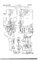
- Figure 1 is a front view of a press having the invention applied thereto, certain parts upon which the invention is not dependent being omitted for the sake of clearness.
- Fig. 2 is a front view of the right end portion of the press drawn to a larger scale, parts being broken away to disclose internal structure.
- Fig. 3 is an end view of the part of the press illustrated in Fig. 2, parts being omitted and parts being broken away to disclose internal structure.
- Fig. 4 is a transverse sectional view of a part of the press illustrated by Fig. 2, the plane of section being represented by the line 4-4, and the parts being viewed in the direction indicated by the arrows.
- Fig. 5 is a detail view of a portion'of the mechanism illustrated in Fig. 2, the parts being represented. as having been locked in the positions to which they are moved in order to set the gauge and separate the feedrolls.
- Fig. 6 is a cross-sectional view of a part of the mechanism illustrated in Fig. 5, the plane of section being represented by the line 6-6, and the parts being viewed in the direction indicated by the arrows.
- Fig. 7 is a diagrammatic representation of the gearing by which the feed-rolls are intermittently rotated.
- Fig. 8 is a diagrammatic plan view of the gearing connecting the feed-rolls at opposite ends of the machine so as to cause them to be rotated in synchronism.
- the press may comprise a frame consisting of a bed supported on legs 21 and having uprights 22 at the opposite ends connected at the top by a head 23.
- a main drive-shaft 24 provided with the usual fly-wheel 25 and having a crank (eccentric) 26 connected by means ofa pitman 27 with a punch or other tool slide 28 mounted forreciprocation in guides 29.
- the means by which sheet material may be fed through the press to be operated on by punches or other tools secured to the slide 28 may comprise pairs of rolls 30, 31, and 80, 31, by which the sheet materialW may be caused to enter the press at the'right side as viewed in Fig. 1, passed over a suitable die mounted on the bed 20 to cooperate with the unches or other tools mounted on the tool slide 28, and thence caused to pass out of the machine at the left end, as indicated by the arrow on Fig. 1.
- these rolls 30, 31 may be intermittently rotated by appropriate gearin connected with the main drive-shaft 24.
- gearing adapted for such use is illustrated and described in the patent to Strout, No. 1,740,844, issued December 24, 1929.
- this gearing may comprise a cran 32 fixedly secured to a gear wheel 33, which may be driven from a gear wheel 34 on the main drive-shaft 24 through the intermediary of an idler 35.
- the movement of the cran 32 may be transmitted to the rolls by means of a pitman 36 connected at one end to the crank and having a rack 37 which may be reciprocated in a guide38 so mounted as to be free to rock about the center of the shaft 39. Mounted in the guide.
- the extent of the rotation to be imparted to the feedrolls at each stroke of the pitman may be varied by making the crank 32 of adjustable length, and, if desired, the motion imparted to the feed-rolls 30, 30 may be positively communicated to feed-rolls 31, 31"
- crank 32 (Fig. 7) should be so positioned with respect to the crank 26 (Figs. 1 7), by which the punch or tool slide 28 is operated, as to cause the feed-rolls to be rotated during the last half of the upward movement and the first half of the downward movement of the slide, and so as to cause the feed-rolls to remain at rest during the last half of the downward movement h and the first half of the upward movement of the slide.
- the feed-rolls 30, 31 and 30, 31' may be mounted in carriages 45 (Figs. 1, 2 and 4), each of which, with its work-support 46 (Fig. 2), may be moved vertically with respect to the frame of the press to a sufli cient extent to the level of the rolls and work-supports 46 with respect to the die or wor -plate (not shown) mounted on the bed 20.
- This may be effected by means of bolts 47 48 (Figs. 2 and 4) having their heads heldin vertical undercut slots or recesses 49 in the frame of the press, and b; nuts 50 which may be loosened to permit t e carriages and the shafting provide for an adjustment of 1 of the roll-rotating mechanism to be raised or lowered.
- the carriages After the loosening of the nuts the carriages may be raised by rotating the lifting screws 51 (Figs. 1 and 2), and, when it is desired to lower the carriages, the screws 51 may be turned in the opposite direction until the carriages are moved to the desired level by the force of gravity.
- This adjustable feature of the carriages for the feed-rolls is more fully illustrated and described in the aforesaid Strout patent.
- the means whereby the roll 31 may be separated from the roll 30 when a new sheet of material is to be inserted may comprise a rock-shaft 52 (Fig. 2) having arms 53 extending underneath the bearings of the roll 31 and an arm 54 by which the rock-shaft may be rotated when the roll is to be lifted.
- Extending inwardly from the rock-shaft 52 is a second arm 55, which may be engaged by a tappet 56', yieldingly mounted in the tool slide 28, as it descends, whereby the roll 31 may be separated from the roll 30 so as to permit the punch or other tool to adjust the position of the plate preparatory to the punching operation or other work to be accomplished.
- a duplicate roll-lifting device having an arm 55 (Fig. 1) to be engaged by a tappet 56, may be provided to separate the rolls 30, 31 at' the left side of the machine as the tool slide approaches the lowermost limit of its stroke.
- the gauge 57 by means of which the end of a new sheet of material to be fed into the press may be accurately positioned, may be izieldingly mounted in a block 58, which may e moved to any desired position along the arm 55 and secured in place by a set screw or other appropriate fastening device 59.
- the rock-shaft 52 carrying the arms 53, 54 and 55 will preferably be mounted, as shown, in the vertically-adjustable roll-carriage, and means now to be described may be mounted on any appropriate part of the frame of the machine whereby the gauge and roll-separating device may be operated.
- One satisfactory form of operating device as best illustrated in Fig. 2, comprises a lever 60 aving an arm 61 to engage a finger or pushpin 62 adjustably mounted in the arm 54, and
- a second arm 63 coupled by means of a connecting rod'64 with a pedal or other suitable operating element 65 pivotally secured to one of the legs 21 at 66.
- the connecting rod 64 may be normally held in av position such as to cause the arm 61 of the lever 60 to be slighty spaced from the end of the push-pin 62 by means of a spring 67 confined between a collar 68, which may be adjustably secured to the connecting rod 64 by a set screw 69, and a lug 70 extendin outwardly from the leg 21 to which the pe a1 is secured.
- This controlling means comprises a bar or bolt 71 (Figs. 2 and 3) movable at its lower end through a guide 72 into a position just back ofa hook or stop 73 on the lever 60 when. it is rocked by the pedal insertion of a new sheet.
- the upper end of the rod 71 may be connected to one arm 74: of a lever 7 5, the other arm 76 of which may be provided with a roller 7 7 to be engaged by a cam 78 on the main drive-shaft 24.
- any appropriate means may be provided to cause the bolt 71 to move to its holding position with respect to the lever 60 when operated to separate the feed-rolls.
- such means comprises a spring 79 having one end connected to the arm 74 of the lever 7 5 and the other connected to any suitable part of the machine frame, as at 80.
- the cam 7 8 on the drive-shaft 24 should be so related with respect to the crank 26 which operates the tool slide28 and the crank 32 (Fig. 7) which operates the gearing by which the feed-rolls are intermittently rotated, as to cause the roller 77 to be free from the cam surface 78 throughout the entire rotational period of the feed-rolls while the tool slide is completing its upward stroke and beginning its downward stroke.
- This will cause the cam 78 to be so positioned with respect to the cranks 32 and 26 as to cause the bolt 71 to be withdrawn from its engagement with the hook or stop 73 at the termination of the rotational period of the feed-rolls and permit them to be restored to their feeding relationship while at rest. This will also take place during the last part of the downward movement of the tool slide and the first part of its upward movement.
- the pedal 65 is depressed in order to set the gauge 57 and separate the feed-rolls preparatory to the The end of this sheet of material is then inserted between the rolls 30,31, until obstructed by the face of the gauge 57.
- the feed-rolls 30, 31 may be rotated any number of times and the punch slide ma be lowered and raised an equal number of times without producing any effect upon the new sheet of material.
- the bar 71 would not hold the rolls 30, 31 separated, and, in the absence of some other means of accomplishing such purpose, it would be necessary for the operator to keep f its stroke and the feed-rolls are be ng rotated, the bolt 71 will be in'engageinentqwithi the g tlon and thus cause the feed-rolls to be sepfeature of the invention, comprising a manually-operative holding element which may be combined withthe above-described automatire'storation of the separated feed-rolls to feedlysoperative holding means, as illustrated in Figs-2 and 3 of the drawings, comprises a cam 81; fixedly secured to a shaft 82 mounted in the frame or bracket 83 in which the lever 6Qispivotally mounted at 84.1
- the hook or to .43',-as bestrepresented in Fig. 6, is of cammay be rotated from the position indileof;1 80 to a position in which the cam 81 will rotate the lever in a clockwise direc- 85 is restored to its normal position.
- the machine should come to rest with the bar 71 out of engagement with the hook or stop 7 3, the feed-rolls may be separated by means of the manually-operative device 81, 85, and held separated at the will of the operator.
- the manually-operativeroll-separating means may be restored to normal position, and, on startin the press, a complete feeding operation Wlll be imparted to the inserted sheet of material.
- the gauge 57 may be set in any desired position along the arm 55 by loosening the setscrew 59, after which it may be thoroughly secured in place, and any dlSaI" 'rangement of the mechanism due to the vertical adjustment of the feed-roll carriage 45 may be compensated for by properly adjusting the effective length of the push-rod or finger 62.
- the invention is not intended to be limited .cluding means for maintaining the holding means ineffective throughout approximately the entire period of rest between each two successive periods of rotation of said rolls.
- the combination with feed-rolls means for intermittently rotating said rolls and means for separating said rolls, of means whereby said rolls may be held in their separated relation, and means whereby the holding means may be intermittently disabled, the rotating means and the disabling means being so related that each is rendered effective throughout substantially the entire ineffective period of the other and neither is rendered effective during an effective period of the other.
- the combination with feed-rolls, means for intermittently rotating said rolls, and means comprising a lever whereby said rolls may be separated, of a stop element on said lever, a bolt, means tending to cause said bolt to be moved into the path of movement of said stop when the lever is operated to separate the rolls and thus revent-the rolls from being restored to a ceding relation, and means including a cam connected in a timed relationship with respect to said roll-rotating means, whereby said bolt may be withdrawn from the path of movement of the stop and held clear of the same while the rolls are at rest, the length and position of the cam being such as to maintain the bolt in its withdrawn position throughout substantially the entire period of rest intervening between each two successive periods of rotation of the rolls.
- a roll-separating mechanism comprising a driving element mounted on a part of the press having a fixed relation with respect to the bed and an element mounted on the roll-carriage in a position such as to be adapted to be driven by said driving element.
- the driving element and the driven element comprise two levers each having an arm substantially parallel to the direction of movement of the carriage in which the rolls are mounted, said arms being arranged in a spaced side-by.-side relation, one of them being provided near its free end with a finger of adjustable length by which movement may be transmitted from one to the other.
- the driven element comprises a rockshaft having means for moving one of the rolls to be separated, and a pair of arms, one provided with a gauge to be-pressed-against a. work-support when the rolls are separated, and one through which motion may be transmitted from the driving element to the gauge and roll.
- the driven element comprises a rockshaft having means for moving one of the rolls to be separated, and a pair of arms, one provided with a gauge adjustable to various positions lengthwise thereof, and one having a finger of adjustable length through which motion may be transmitted from the driving element to the gauge and roll.
Landscapes
- Engineering & Computer Science (AREA)
- Mechanical Engineering (AREA)
- Bending Of Plates, Rods, And Pipes (AREA)
Description
E. V. CRANE March 29, 1932.
GAUGE AND STARTING MECHANISM FOR PRESSES AND ANALOGOUS MACHINES Filed Aug. 5. 1930 2 Sheets-Sheet 1 INVENTOR fl fl'm,
By Attorneys, Jaw ,777 q! i1 P mumnvmm l March 29, 1932. E v CRANE 1,851,753
GAUGE AND STARTING MECHANISM FOR PRESSEJS AND ANALOGOUS MACHINES speed of -EDWABD V. CRANE, O1 BROOKLYN,
the press such as would result if the fee Patented Mar. 29, 1932.
uurrso STATES PATENT OFFICE OF NEW YORK,N. Yr,
NEW YORK, ASSIGNOR TO. E..W. BLISS COMPANY,
A CORPORATION OF DELAWARE .GAUGEAND STAB'I'INGiEECHANISK FOR PRESSES AND ANALOGCUS MACHINES Application filed August 5, 1930. Serial No. 473,270.
This invention relates to an improved gauge and starting mechanism for presses and analogous machines having intermittent feeding means. It is particularly adapted for use on punch presses and similar devices having means for intermittently feeding and operating on sheet ,metal, and in which the operation is such as to make hand gaugin and starting impracticable, if not impossi le.
It is an object of the invention to provide means whereby the intermittently-operated feed-rolls may be separated as the gaugefor positioning a new sheet of material to be fed into the press is set, and means controlled and operated by the driving mechanism of whereby return movement of the gauge to free the sheet and the restoration of the feed-rolls to their feeding relationship may be prevented throughout the rotational period of the feed-rolls but permitted throughout substantially the entire period during which the feed-rolls are at. rest, thus preventing an incomplete feedinfoperation -rolls were restored to their feedingrelationduring the period of rotation.
It is a further object of the invention to.
provide a press or analogous machine with a gauge and starting mechanism of the above-- described character, the parts of the improvement being so related to the feed-rolls that the latter may be adjusted as to their position with respect to the body portion of the machine without interfering with the proper transmission of movement from the parts of the mechanism mounted on the body portion to those mounted on the relatively movable portion in which the adjustable elements are carried.
In the accompanying drawings illustrating the preferred form of the invention- Figure 1 is a front view of a press having the invention applied thereto, certain parts upon which the invention is not dependent being omitted for the sake of clearness.
Fig. 2 is a front view of the right end portion of the press drawn to a larger scale, parts being broken away to disclose internal structure.
Fig. 3 is an end view of the part of the press illustrated in Fig. 2, parts being omitted and parts being broken away to disclose internal structure.
Fig. 4 is a transverse sectional view of a part of the press illustrated by Fig. 2, the plane of section being represented by the line 4-4, and the parts being viewed in the direction indicated by the arrows.
Fig. 5 is a detail view of a portion'of the mechanism illustrated in Fig. 2, the parts being represented. as having been locked in the positions to which they are moved in order to set the gauge and separate the feedrolls.
Fig. 6 is a cross-sectional view of a part of the mechanism illustrated in Fig. 5, the plane of section being represented by the line 6-6, and the parts being viewed in the direction indicated by the arrows.
Fig. 7 is a diagrammatic representation of the gearing by which the feed-rolls are intermittently rotated.
Fig. 8 is a diagrammatic plan view of the gearing connecting the feed-rolls at opposite ends of the machine so as to cause them to be rotated in synchronism.
Referring first to Fig. 1, the press may comprise a frame consisting of a bed supported on legs 21 and having uprights 22 at the opposite ends connected at the top by a head 23.
In any appropriate part of the frame may be mounted a main drive-shaft 24 provided with the usual fly-wheel 25 and having a crank (eccentric) 26 connected by means ofa pitman 27 with a punch or other tool slide 28 mounted forreciprocation in guides 29.
The means by which sheet material may be fed through the press to be operated on by punches or other tools secured to the slide 28 may comprise pairs of rolls 30, 31, and 80, 31, by which the sheet materialW may be caused to enter the press at the'right side as viewed in Fig. 1, passed over a suitable die mounted on the bed 20 to cooperate with the unches or other tools mounted on the tool slide 28, and thence caused to pass out of the machine at the left end, as indicated by the arrow on Fig. 1.
These rolls 30, 31 may be intermittently rotated by appropriate gearin connected with the main drive-shaft 24. he form of gearing adapted for such use is illustrated and described in the patent to Strout, No. 1,740,844, issued December 24, 1929. As briefly illustrated by the diagrams F1 s. 7 and 8, this gearing may comprise a cran 32 fixedly secured to a gear wheel 33, which may be driven from a gear wheel 34 on the main drive-shaft 24 through the intermediary of an idler 35. The movement of the cran 32 may be transmitted to the rolls by means of a pitman 36 connected at one end to the crank and having a rack 37 which may be reciprocated in a guide38 so mounted as to be free to rock about the center of the shaft 39. Mounted in the guide. 38 is a one-way clutch 40 having peripheral teeth in meshed engagement with the rack 37 and a friction driving element by which it is connected with the shaft 39. This connection, as more fully illustrated and described in the aforesaid Strout patent, is such that on downward movement of the pitman the shaft is rotated, whereas on upward movement of the pitman the shaft remains at rest. These intermittent rotations of the shaft 39 may be communicated to the lower feed-rolls 30, 30' by means of bevel gears 41, 41, fixedly secured to the shaft and bevel gears 42, 42, fixedly secured to the shafts carrying the rolls.
The extent of the rotation to be imparted to the feedrolls at each stroke of the pitman may be varied by making the crank 32 of adjustable length, and, if desired, the motion imparted to the feed- rolls 30, 30 may be positively communicated to feed- rolls 31, 31"
in any appropriate manner, as by means of meshed spur gears 43, 44, and 43, 44.
Preferably the crank 32 (Fig. 7) should be so positioned with respect to the crank 26 (Figs. 1 7), by which the punch or tool slide 28 is operated, as to cause the feed-rolls to be rotated during the last half of the upward movement and the first half of the downward movement of the slide, and so as to cause the feed-rolls to remain at rest during the last half of the downward movement h and the first half of the upward movement of the slide. 1
If desired, the feed- rolls 30, 31 and 30, 31' may be mounted in carriages 45 (Figs. 1, 2 and 4), each of which, with its work-support 46 (Fig. 2), may be moved vertically with respect to the frame of the press to a sufli cient extent to the level of the rolls and work-supports 46 with respect to the die or wor -plate (not shown) mounted on the bed 20. This may be effected by means of bolts 47 48 (Figs. 2 and 4) having their heads heldin vertical undercut slots or recesses 49 in the frame of the press, and b; nuts 50 which may be loosened to permit t e carriages and the shafting provide for an adjustment of 1 of the roll-rotating mechanism to be raised or lowered. After the loosening of the nuts the carriages may be raised by rotating the lifting screws 51 (Figs. 1 and 2), and, when it is desired to lower the carriages, the screws 51 may be turned in the opposite direction until the carriages are moved to the desired level by the force of gravity. This adjustable feature of the carriages for the feed-rolls is more fully illustrated and described in the aforesaid Strout patent.
The means whereby the roll 31 may be separated from the roll 30 when a new sheet of material is to be inserted may comprise a rock-shaft 52 (Fig. 2) having arms 53 extending underneath the bearings of the roll 31 and an arm 54 by which the rock-shaft may be rotated when the roll is to be lifted. Extending inwardly from the rock-shaft 52 is a second arm 55, which may be engaged by a tappet 56', yieldingly mounted in the tool slide 28, as it descends, whereby the roll 31 may be separated from the roll 30 so as to permit the punch or other tool to adjust the position of the plate preparatory to the punching operation or other work to be accomplished. A duplicate roll-lifting device, having an arm 55 (Fig. 1) to be engaged by a tappet 56, may be provided to separate the rolls 30, 31 at' the left side of the machine as the tool slide approaches the lowermost limit of its stroke.
The gauge 57, by means of which the end of a new sheet of material to be fed into the press may be accurately positioned, may be izieldingly mounted in a block 58, which may e moved to any desired position along the arm 55 and secured in place by a set screw or other appropriate fastening device 59.
The rock-shaft 52 carrying the arms 53, 54 and 55 will preferably be mounted, as shown, in the vertically-adjustable roll-carriage, and means now to be described may be mounted on any appropriate part of the frame of the machine whereby the gauge and roll-separating device may be operated. One satisfactory form of operating device, as best illustrated in Fig. 2, comprises a lever 60 aving an arm 61 to engage a finger or pushpin 62 adjustably mounted in the arm 54, and
a second arm 63 coupled by means of a connecting rod'64 with a pedal or other suitable operating element 65 pivotally secured to one of the legs 21 at 66. The connecting rod 64 may be normally held in av position such as to cause the arm 61 of the lever 60 to be slighty spaced from the end of the push-pin 62 by means of a spring 67 confined between a collar 68, which may be adjustably secured to the connecting rod 64 by a set screw 69, and a lug 70 extendin outwardly from the leg 21 to which the pe a1 is secured.
On pressin spring 67 wil be compressed and the lever 60 will be rocked to a position such as to enthe pedal downwardly the v constitutes another important gage and move the push-pin 62 and arm 54 in which it is mounted, thus rotating the rock-shaft 52 and causing the gauge 57 to be set and the feed-roll 31 to be se arated from the roll 30 as indicated in ig. 5. Springs of any appropriate strength (not shown) may be provided to restore the feedroll 31 to its feedin position with respect to the feed-roll 30 a ter aplate has been inserted and the pedal released.
It is important that the relations between the parts of the gauge-setting and roll-separating device mounted in the vertically-adjustable carriage 45 and the parts of the device mounted on the machine frame be such that the rolls may be separated and the gauge set by the operation of the pedal irrespective of the varyin positions of adiustment of the carriage. is is satisfactori y effected by the mechanism herein disclosed, having the operating arm 54-, on the rock-shaft 52 and the arm 61- of the lever disposed in a relationship of approximate parallelism so that the rocking of the lever 60 will rock the shaft 52 throu h the intermediary of the push-pin 62 and arm 54, irrespective of the vertical displacements of the carriage, to adjust the feed-rolls to different positions relative' to the dies or tools used in the press. This is one of the important novel features of the invention.
In a machine of the above-described char acter it is of importance that the restoration, of the feed-rolls to their feedin relationship, after they have been separate for the pur" pose of inserting and gauging the position of a new sheet of material, take place while the feed-rolls are at rest, so that the first rotative period of the feed-rolls will impart to the sheet a movement equal to-that which it receives at each subsequentrotative period of the rolls. In machines in which the feeding is of relatively low speed this can be accomplished by a hand manipulation of the operator, who, by careful observation, can determine the proper time to release the pedal and permit the rolls to be restored to feeding relation. In high speed machines this is practically impossible. Without the aid of automatic controlling means the rolls wouldoccasionally, if not frequently, be permitted to be restored to their feeding relatlonship durin one of the rotative periods of the feedro ls, thus causing the sheet to receive but a partial advancement prior to thefirst operation of the punch or other tool carried by the tool slide. The automatic means, now to be described, for controllin the restoration of the feed-rolls to their eedin relationship eature of this invention. This controlling means comprises a bar or bolt 71 (Figs. 2 and 3) movable at its lower end through a guide 72 into a position just back ofa hook or stop 73 on the lever 60 when. it is rocked by the pedal insertion of a new sheet.
and connectingrod 64 to the position in which it causes the roll 31 to be separated from the roll 30. The upper end of the rod 71 may be connected to one arm 74: of a lever 7 5, the other arm 76 of which may be provided with a roller 7 7 to be engaged by a cam 78 on the main drive-shaft 24.
Any appropriate means may be provided to cause the bolt 71 to move to its holding position with respect to the lever 60 when operated to separate the feed-rolls. As herein disclosed, such means comprises a spring 79 having one end connected to the arm 74 of the lever 7 5 and the other connected to any suitable part of the machine frame, as at 80.
The cam 7 8 on the drive-shaft 24 should be so related with respect to the crank 26 which operates the tool slide28 and the crank 32 (Fig. 7) which operates the gearing by which the feed-rolls are intermittently rotated, as to cause the roller 77 to be free from the cam surface 78 throughout the entire rotational period of the feed-rolls while the tool slide is completing its upward stroke and beginning its downward stroke. This will cause the cam 78 to be so positioned with respect to the cranks 32 and 26 as to cause the bolt 71 to be withdrawn from its engagement with the hook or stop 73 at the termination of the rotational period of the feed-rolls and permit them to be restored to their feeding relationship while at rest. This will also take place during the last part of the downward movement of the tool slide and the first part of its upward movement.
he operation of the machine need be but briefly described in View of the foregoing disclosure of the various parts of the mechanism.
Assuming that the press is in operation and that all of the required work on one sheet of material has been completed, the pedal 65 is depressed in order to set the gauge 57 and separate the feed-rolls preparatory to the The end of this sheet of material is then inserted between the rolls 30,31, until obstructed by the face of the gauge 57. During this operation the feed- rolls 30, 31 may be rotated any number of times and the punch slide ma be lowered and raised an equal number of times without producing any effect upon the new sheet of material. a When the sheet has been properly ositioned the operator releases the pedal 65.
hould he release the pedal at a time when the punch slide is completing its downward stroke or commencing its upward stroke, durin which the feed-rolls will be at rest, the ho t 71 will not lock the lever 60 and the rollseparating means will be permitted to immediately restore the rolls to their feeding operation so that, as the punch slidecompletes its upward stroke and commences its downward stroke,the feed-rolls will becaused to feed the sheet to the proper position to receive the punch or other tools mounted in the press. The feeding will then continue 'ly cooperate with the automatically, but intermittently, without further attention by the operator. At the end of each downward stroke of the punch slide the tappets 56, 56' will engage the arms .55, and momentarily separate the rolls.
as the tools justif the position of the sheet v v cally-operated hold ng means by which the just prior to punc ing orotherwise working upon it. As the punch or tool slide ascends 1 ing relationship is prevented. This manualit will free the arms 55, 55 and permit the rolls to be restored to their feeding relationship while still at rest, after which another feedingoperation will be im arted to the sheet while the unch or tool side'com letes its upward stro e'and commencesitfsi oWn'j-W ward stroke. When theworku on the sheet; f at i l h b lete and a g suflicient width to receive the bolt 71 and thecam 81' in side-by-side relation. To the shaft "82, to which the cam is fixedly secured, is
sheet. is to be inserted, the, Operationjisf re." peated.
If, when the pedal is released after posi i tionin and gaugin .a new plate-tobefed I y cated ins-F 1g..2, in which the feed-rolls may. restiin'their feeding relation, through an aninto t e press,-it s ould'fhappenfth punch or tool slide is at' the. up ferjp hook or stop 7 3 andpre'vent the return ofthe feed-rolls to their feeding. relationship; However, after the rotation of the feed-rolls has ceased and the toolslide is approaching the end of 'its downward stroke, the cam 78 will engage the roller 77 and cause thebolt 71 to release the hook or stop 73 and permit the roll-separating means to restore the rolls to their feeding relationship, thus insuring a feeding operation to be imparted to the newly-inserted plateof exactly the same ex-. sequently imtent as those which will be su parted during the automatic operation of the machine. V p i I g Under certain circumstances it isiof importance that the restoration'ofthe feed-rolls to feeding relationship may be prevented when the machine is atjrest by means which is not de endent upon: the position of the drive-she t. For example, if itis desired to use the machine to work on a relatively thin plate, it may not bep'o'ssible to depend upon the feed- rolls 30, 31 at the'right side of the machine to advance the plate through the machine to the feed-rolls 30', 31:, at the left side of the machine. When working on such thin material it is the practice to draw the plate entirely through the machine while at rest, until its leading end has been passed through the feed- rolls 30, 31, which will subsequentrolls 30, 31 at the right side of the machine to keep the plate flat while it is being worked upon. Should the machine, when stoppedto insert a. thin plate in this mannerfcome to rest with the cam 78 in engagement with the roller 77 (Fig. 3), the bar 71 would not hold the rolls 30, 31 separated, and, in the absence of some other means of accomplishing such purpose, it would be necessary for the operator to keep f its stroke and the feed-rolls are be ng rotated, the bolt 71 will be in'engageinentqwithi the g tlon and thus cause the feed-rolls to be sepfeature of the invention, comprising a manually-operative holding element which may be combined withthe above-described automatire'storation of the separated feed-rolls to feedlysoperative holding means, as illustrated in Figs-2 and 3 of the drawings, comprises a cam 81; fixedly secured to a shaft 82 mounted in the frame or bracket 83 in which the lever 6Qispivotally mounted at 84.1 The hook or to .43',-as bestrepresented in Fig. 6, is of cammay be rotated from the position indileof;1 80 to a position in which the cam 81 will rotate the lever in a clockwise direc- 85 is restored to its normal position. If,
therefore, the machine should come to rest with the bar 71 out of engagement with the hook or stop 7 3, the feed-rolls may be separated by means of the manually- operative device 81, 85, and held separated at the will of the operator. When it is desired to start the machine the manually-operativeroll-separating means may be restored to normal position, and, on startin the press, a complete feeding operation Wlll be imparted to the inserted sheet of material.
. When pre aring the press to receive a new piece of wor z, the gauge 57 may be set in any desired position along the arm 55 by loosening the setscrew 59, after which it may be thoroughly secured in place, and any dlSaI" 'rangement of the mechanism due to the vertical adjustment of the feed-roll carriage 45 may be compensated for by properly adjusting the effective length of the push-rod or finger 62.
The invention is not intended to be limited .cluding means for maintaining the holding means ineffective throughout approximately the entire period of rest between each two successive periods of rotation of said rolls.
2. In a machine, the combination with feed-rolls, means for intermittently rotating said rolls and means for separating said rolls, of means whereby said rolls may be held in their separated relation, and means whereby the holding means may be intermittently disabled, the rotating means and the disabling means being so related that each is rendered effective throughout substantially the entire ineffective period of the other and neither is rendered effective during an effective period of the other.
3. In a machine, the combination with feed-rolls, a drive-shaft, means connecting said shaft with said rclls whereby the latter may be rotated intermittently and means for separating said rolls, of a locking device to engage a cooperating portion of the rollseparating means if operated to separate the rolls during a period of rotation, and an operating element on said drive-shaft to intermittently cause said locking device to be rendered ineffective, said operating element and rotating means being so related as to cause the locking device to be effective throughout each rotational period of the rolls and to be rendered ineffective throughout substantially the whole of each period of rest between their successive rotational periods.
4. In a machine, the combination with feed-rolls, means for intermittently rotating said rolls, and means comprising a lever whereby said rolls may be separated, of a stop element on said lever, a bolt, means tending to cause said bolt to be moved into the path of movement of said stop when the lever is operated to separate the rolls and thus revent-the rolls from being restored to a ceding relation, and means including a cam connected in a timed relationship with respect to said roll-rotating means, whereby said bolt may be withdrawn from the path of movement of the stop and held clear of the same while the rolls are at rest, the length and position of the cam being such as to maintain the bolt in its withdrawn position throughout substantially the entire period of rest intervening between each two successive periods of rotation of the rolls.
5. In a machine, the combination with a work-bed, feed-rolls to feed work over said bed and a movable carriage for said rolls whereby their positions with respect to the bed may be adjusted, of a roll-separating mechanism comprising a driving element mounted on a part of the press having a fixed relation with respect to the bed and an element mounted on the roll-carriage in a position such as to be adapted to be driven by said driving element.
6. The combination defined by claim 5, of which the driving element and the driven element comprise two levers each having an arm substantially parallel to the direction of movement of the carriage in which the rolls are mounted, said arms being so related as to cooperate with each other as movementtransnntting means when the carnage is in any of its various positions of adjustment with respect to the work-bed.
7. The combination defined by claim 5, of which the driving element and the driven element comprise two levers each having an arm substantially parallel to the direction of movement of the carriage in which the rolls are mounted, said arms being arranged in a spaced side-by.-side relation, one of them being provided near its free end with a finger of adjustable length by which movement may be transmitted from one to the other.
8. The combination defined by claim 5, of which the driven element comprises a rockshaft having means for moving one of the rolls to be separated, and a pair of arms, one provided with a gauge to be-pressed-against a. work-support when the rolls are separated, and one through which motion may be transmitted from the driving element to the gauge and roll.
9. The combination defined by claim 5, of which the driven element comprises a rockshaft having means for moving one of the rolls to be separated, and a pair of arms, one provided with a gauge adjustable to various positions lengthwise thereof, and one having a finger of adjustable length through which motion may be transmitted from the driving element to the gauge and roll.
In witness whereof, I have hereunto my name.
EDWARD V. CRANE.
signed
Priority Applications (1)
| Application Number | Priority Date | Filing Date | Title |
|---|---|---|---|
| US473270A US1851753A (en) | 1930-08-05 | 1930-08-05 | Gauge and starting mechanism for presses and analogous machines |
Applications Claiming Priority (1)
| Application Number | Priority Date | Filing Date | Title |
|---|---|---|---|
| US473270A US1851753A (en) | 1930-08-05 | 1930-08-05 | Gauge and starting mechanism for presses and analogous machines |
Publications (1)
| Publication Number | Publication Date |
|---|---|
| US1851753A true US1851753A (en) | 1932-03-29 |
Family
ID=23878866
Family Applications (1)
| Application Number | Title | Priority Date | Filing Date |
|---|---|---|---|
| US473270A Expired - Lifetime US1851753A (en) | 1930-08-05 | 1930-08-05 | Gauge and starting mechanism for presses and analogous machines |
Country Status (1)
| Country | Link |
|---|---|
| US (1) | US1851753A (en) |
Cited By (10)
| Publication number | Priority date | Publication date | Assignee | Title |
|---|---|---|---|---|
| US2425382A (en) * | 1945-04-26 | 1947-08-12 | Western Electric Co | Apparatus for advancing strip material |
| US2551985A (en) * | 1946-09-20 | 1951-05-08 | Clair B Weller | Ticket forming and marking machine |
| US2598323A (en) * | 1947-01-13 | 1952-05-27 | Wagar Harold Kenneth | Foil feeder for printing or embossing machines |
| US2693955A (en) * | 1949-03-12 | 1954-11-09 | Frederick K Maust | Control unit for stock feed |
| US2728571A (en) * | 1949-08-31 | 1955-12-27 | Alvin F Groll | Strip stock feeders |
| US2797087A (en) * | 1954-02-23 | 1957-06-25 | Kirsch Co | Automatic die feeder |
| US2819070A (en) * | 1953-08-18 | 1958-01-07 | Herr Equipment Corp | Mechanical movement particularly for feed apparatus |
| US2827120A (en) * | 1954-06-11 | 1958-03-18 | Standard Register Co | Strip feeding and cutting mechanism |
| US2840369A (en) * | 1956-02-06 | 1958-06-24 | Progressive Machinery Corp | Stock-feeding apparatus |
| US3013708A (en) * | 1960-01-13 | 1961-12-19 | Bliss E W Co | Roll feed |
-
1930
- 1930-08-05 US US473270A patent/US1851753A/en not_active Expired - Lifetime
Cited By (10)
| Publication number | Priority date | Publication date | Assignee | Title |
|---|---|---|---|---|
| US2425382A (en) * | 1945-04-26 | 1947-08-12 | Western Electric Co | Apparatus for advancing strip material |
| US2551985A (en) * | 1946-09-20 | 1951-05-08 | Clair B Weller | Ticket forming and marking machine |
| US2598323A (en) * | 1947-01-13 | 1952-05-27 | Wagar Harold Kenneth | Foil feeder for printing or embossing machines |
| US2693955A (en) * | 1949-03-12 | 1954-11-09 | Frederick K Maust | Control unit for stock feed |
| US2728571A (en) * | 1949-08-31 | 1955-12-27 | Alvin F Groll | Strip stock feeders |
| US2819070A (en) * | 1953-08-18 | 1958-01-07 | Herr Equipment Corp | Mechanical movement particularly for feed apparatus |
| US2797087A (en) * | 1954-02-23 | 1957-06-25 | Kirsch Co | Automatic die feeder |
| US2827120A (en) * | 1954-06-11 | 1958-03-18 | Standard Register Co | Strip feeding and cutting mechanism |
| US2840369A (en) * | 1956-02-06 | 1958-06-24 | Progressive Machinery Corp | Stock-feeding apparatus |
| US3013708A (en) * | 1960-01-13 | 1961-12-19 | Bliss E W Co | Roll feed |
Similar Documents
| Publication | Publication Date | Title |
|---|---|---|
| US1851753A (en) | Gauge and starting mechanism for presses and analogous machines | |
| US1917359A (en) | Can making machine | |
| US2012423A (en) | Blanking and forming press and method of forming blanks | |
| US2394534A (en) | Forming machine and feeding device therefor | |
| US2278921A (en) | Strip stock feed mechanism | |
| US2049915A (en) | Multiple transfer press | |
| US2026135A (en) | Stapling and stitching mechanism for rotary printing machines | |
| US1952195A (en) | Crank operated eyelet machine | |
| GB1086046A (en) | Improvements in automatic presses | |
| US3782231A (en) | Piercing assembly | |
| US2614515A (en) | Hood forming machine | |
| US2534780A (en) | Work feeding means for presses | |
| US2783996A (en) | Feed roll drive and brake mechanism therefor for presses of the punch and blanking type | |
| US1963491A (en) | Wire or strip blanking machine | |
| US2840369A (en) | Stock-feeding apparatus | |
| US2569976A (en) | Means for automatically and intermittently feeding blanks of cardboard or similar sheet material | |
| USRE18715E (en) | hutchinson r | |
| US2255096A (en) | Heading machine | |
| US2033993A (en) | Process of stamping blanks | |
| US1534100A (en) | Machine for manufacturing crimped paper cups | |
| US1872474A (en) | Automatic punch press | |
| US2047337A (en) | Edging of fabrics or other materials | |
| US3002204A (en) | Multiple station forging machine with work transfer means | |
| US1819044A (en) | Nut machine | |
| US1824957A (en) | Duplex fastener setting machine |