US1851748A - Method and apparatus for coding and decoding - Google Patents
Method and apparatus for coding and decoding Download PDFInfo
- Publication number
- US1851748A US1851748A US446258A US44625830A US1851748A US 1851748 A US1851748 A US 1851748A US 446258 A US446258 A US 446258A US 44625830 A US44625830 A US 44625830A US 1851748 A US1851748 A US 1851748A
- Authority
- US
- United States
- Prior art keywords
- cylinder
- document
- motor shaft
- generatrix
- cam
- Prior art date
- Legal status (The legal status is an assumption and is not a legal conclusion. Google has not performed a legal analysis and makes no representation as to the accuracy of the status listed.)
- Expired - Lifetime
Links
- 238000000034 method Methods 0.000 title description 10
- 239000012141 concentrate Substances 0.000 description 8
- 230000003287 optical effect Effects 0.000 description 8
- 238000006073 displacement reaction Methods 0.000 description 6
- 230000010355 oscillation Effects 0.000 description 5
- 230000005540 biological transmission Effects 0.000 description 3
- 244000027321 Lychnis chalcedonica Species 0.000 description 2
- 230000001788 irregular Effects 0.000 description 2
- IVQOFBKHQCTVQV-UHFFFAOYSA-N 2-hydroxy-2,2-diphenylacetic acid 2-(diethylamino)ethyl ester Chemical compound C=1C=CC=CC=1C(O)(C(=O)OCCN(CC)CC)C1=CC=CC=C1 IVQOFBKHQCTVQV-UHFFFAOYSA-N 0.000 description 1
- 101100400378 Mus musculus Marveld2 gene Proteins 0.000 description 1
- 239000000203 mixture Substances 0.000 description 1
- 230000002093 peripheral effect Effects 0.000 description 1
- 230000002250 progressing effect Effects 0.000 description 1
Images

Classifications
-
- H—ELECTRICITY
- H04—ELECTRIC COMMUNICATION TECHNIQUE
- H04N—PICTORIAL COMMUNICATION, e.g. TELEVISION
- H04N1/00—Scanning, transmission or reproduction of documents or the like, e.g. facsimile transmission; Details thereof
- H04N1/44—Secrecy systems
- H04N1/448—Rendering the image unintelligible, e.g. scrambling
Definitions
- the present invention relates to a method and apparatus for coding and decoding.
- the object of the invention is to provide a method and apparatus for deforming the '5 writing on a document prior to its transmission and for correcting the deformation in a receiving system.
- the document to be transmitted will, in accordance with the present invention, be illegible even to the operator transmitting the message. Similarly, the operator at the receiving station of the transmitting system will see only an illegible, deformed document.
- the person possessing the re-composing apparatus is the only one who will be able to transform the illegible message transmitted into a replica of 50 the original document used for transmission. Therefore, all danger of any third party learning the contents of the transmitted document is thus eliminated. Transmitting may be effected without any special precautions in the ordinary apparatus now in general use for transmitting documents electrically.
- the basic principle upon which the invention operates consists in scanning parts of j the document in narrow parallel bands or lines.
- the lines of the document are deformed longitudinally so that points thereon occupy positions diflerent from those on the original to be transmitted.
- the imbroglio may be complicated by positioning certain characters without significance along the margins.
- Fig. 1 illustrates diagrammatically one constructive embodiment of the invention in part
- Fig. 1a shows diagrammatically the additional part to Fig. 1;
- FIG. 2 is an illustration of the optical sys tem of Figure 1;
- Fig. 3' is an elevation of the anti-duplicatmg system
- Fig. 3a is a side elevational view of the apparatus shown in Fig. 3;.
- Fig. 4 shows a mechanism for varying the rate of advance of the receiving apparatus.
- Def or-mz'ng apparatus The document to be deformed is applied to cylinder 1 which is illuminated along a generatrix a over a width of one third of a mm. by means of any convenient optical system.
- a lamp S and a cylindric lens L as shown on Figures 1 and 2; a slit F is placed on the path of the luminous beam after reflexion on the cylinder 1, so as to give a plane beam P (Fig. 2) whose width is equal to that-of generatrix a, i. e. one third of a mm.
- This beam falls upon an oscillatipg mirror 35, which rejects the beam on an objective 0; this objective 0 concentrates the beam on a photographic film or paper applied to cylinder 6 which is enclosed in opaque chamber 7, 8 through which it is possible to obtain a punctual aperture, which is displaced along a given generatrix as will be explained hereinafter.
- the mirror 35 is given a slow movement of small amplitude about an axis perpendicular to generatrix a.
- Chamber 7, 8 is composed of two concentrio cylinders. Interior cylinder 7 is fixed in position and provided with a long tudinal slot 7'. Exterior cylinder 8 rotates at uniform speed about its axis and is provided with a. helicoidal slot 8 on one half of its periphery. The light reflected from mirror 35 traverses slots 7 and 8 and yields a punctiform beam at their point of intersection which falls upon the photo-sensitive. film or paper on cylinder 6 to give the deformed image used for transmission.-
- Photographic cylinder 6 is displaced angularly by predetermined amounts in a manner to be described further on; the movement is given by the main motor shaft M to a system which shall be hereinafter described and which gives the cylinder 6 Variable displacements.
- cylinder 1 is rotated through a distance corresponding to one third of :1 mm.
- a cam 52 breaks the circuit to the solenoid controlling cylinder 1 thus preventing further displacement of the latter and obviating the loss of non-photographed lines.
- Mirror 35 is actuated by pinion 28 driving Maltese cross 25, simple or eccentric gear systems of the type 28, 27, 34, 39, being interposed to vary the character of its displacement. 1
- Assembly for obtaining variable advanee 23 contacts with anyone of a plurality of pins 72 mounted on a rotatable support 24.
- support 24' is rotated by a mechanism to be described further on, so that the pins 39 mounted thereon are brought successively under lever 23.
- Ratchet Wheel 20 is thus displaced through distances varying with the height of the pins 10 on support 24.
- Rotation of 24 is efi'ected by means of the Maltese cross 25 driven from the main motor shaft by auxiliary shaft 29 and plate 26 carrying an extension.
- Anti-duplicating system an example, to 3, 7, 11, 9, 13 teeth, occurring periodically in accordance with the number of pins on support 24.
- the sum of the advances during any given period should be prime with the number of teeth on ratchet wheel 20.
- certain generatrices would be repeated before arriving at the final line. But since any given generatrix can only be exposed once, means must be provided for preventing super-position of any pair of lines, i. e., an anti-duplicating system must be'employed.
- Anti-duplicator 36 includes a circular crown provided with as many keys 41 as there are teeth on ratchet Wheel 20. Rotation of 36 brings an explorer 42 in front of some one key 41. At each stop, explorer 42 is displaced radially by a system of levers 37 controlled by a cam 37 driven by shaft m and, contacting with corresponding key 41, closes the circuit to solenoid 3. As soon as contact is established, a pusher 43, actuated in an analo ous manner b lever s stem 372 dis- O 7 places key 41 radially so that the latter is out of the range of explorer 42 during further explorations. During this period, cylinder 1 is arrested until a new photographic impression is to be made.
- a shutter 19 is placed in the optical system between mirror 35 and cylinder 8, to prevent re-exposure.
- the shutter 19 is opened under the action of a solenoid 18 in series with solenoid 3 and closes automatically duringthe half (dead) revolution of cylinder 6.
- Dividing system In order to explore a cylinder by thirds of a mm., wheels of disproportionated diameter would have to be used if a proper form of teeth is to be used i. e., about 2 mms. With wheels 100 mm. in diameter carrying 149 teeth, prime number, a peripheral advance of 1 mm. requires a 50 mm. cylinder.
- the dividing system to be described efi'ects an exploration of one third of cylinder 1, the latter progressing by one third mm. by means of a reducing system of 1 to 3. Since the progression of cylinder 6 bandwise is difiicult to maintain correctly, the latter is driven directly without reduction i. e., by multiples of mms.
- the 149 following are intercalated in the first third of a mm. left between the first; then the third and last series of 149 is inserted in the second third of the same interval.
- the mechanism employed is simply a ratchet wheel 18 yielding a displacement of 4/3 of a tooth instead of 1/3.
- This mechanism enters into action only twice in the course of each cryptograph, once after the series of 149 lines, and the second time after the-second series. It is actuated by solenoid 19. After each series, all of keys 41 which are displaced radially, are moved back into operating position by a cable in external contact therewith and manually actuated.
- cylinder 1 supports the deformed document and cylinder 6, the photographic film or paper which receives the decoded document.
- cylinder 8 is rotated by pinions 9, 10, and is rotatably supported on yoke and roller 12 mounted in a casing 13 supported on said cylinder.
- Carriage 14 serves forthe rearward movement of cylinder assembly 7, 8, when cylinder 6 has to be charged with the photo-sensitive film or plate. Rotation on cylinder 8 is effected by plate 15.
- An apparatus of the class described comprisingin combination a support adapted to carry the document to be transmitted, means for producing a deformed image of the exploration generatrices of the document by arbitrarily transmitting lines on a second support carrying a photo-sensitive surface and means for putting the generatrices.
- An apparatus of the character described comprising in combination a rotatable cylinder adapted to carry the document to be transmitted, a cam, an electromagnet, a main motor shaft carrying the cam which during each turn closes a circuitactuating the electromagnet controlling the rotation of the rotatable cylinder, means for forming a deformed image of the exploration generat-rices of the document on a second support carrying a photo-sensitive surface and means for putting said generatrices in a variable order to render the same illegible.
- An apparatus of the character described comprising in combination an electromagnetically actuated rotatable cylinder adapted to carry the document to be transmitted, a'main motor shaft, a cam supported by the main motor shaft for controlling the electromagnet, an optical system lighting the document supported by the said rotatable cylinder along a generatrix, means for forming a deformed image of the explorated'generatrix on a second cylinder carrying a photo-sensitive surface and means for putting the successive generatrices in a variable order to render the same illegible.
- An apparatus of the class described comprising in combination a rotatable cylinder adapted to carry the document to be transmitted and actuated by an electro-magnet controlled by a cam supported by. the main motor shaft, an optical system comprising a luminous source and a cyllndric lens to concentrate the beam along ageneratrlx of the cylinder, means for forming a deformed image of the explorated generatrix on a second cylinder carrying a photo-sensitive surface and means for putting the successive generatrices in a variable order to render the same-illegible.
- An apparatus of the character described comprising in combination, a rotatable cylinder adapted to carry the document to be transmitted and being actuated by an electro-magnet which being controlled by a cam supported by the main motor shaft, an optical system comprising a luminous source and a cylindric lens concentrating the beam along a generatriz; of the cylinder, a slit after the cylinder, giving a band of light reflected by an oscillating mirror on an objective which concentrates the said band on a generatrix of the second cylinder, a cylindric case concentric with the second cylinder and composed of two concentric cylinders, interior cylinder fixed in position and provided with a longitudinal slot, and an exterior cylinder rotating at uniform speed about its axis and being provided with a helicoidal slot on one half of its periphery and means for putting the successive generatrices in a variable order to render the received document illegible.
- Anapparatus of the character described comprising in combination, an electromagnetically actuated rotatable cylinder adapted to carry the document to be transmitted, a main motor shaft, a cam supported second cylinder and composed of two concen-.
- An apparatus of the character de scribed comprising in combination an electromagnetically actuated rotatable cylinder adapted to carry the document to be transmitted, a main motor shaft, a cam supported by the main motor shaft for controlling the electromagnet, an optical system comprising the second cylinder, a cylindric case concentric with the second cylinder and composed of two concentric cylinders, an interior cylinder being fixed in position and provided with a longitudinal slot and an exterior cylinder rotating at uniform speed about its axis and being provided with a helicoidal slot on one half of its periphery, means for tran's uniting the movement of the motor shaft to an oscillating lever in two parts, one of which raises the second one, which falls back on. pimof different heights and controls the corresponding rotation of a wheel leading the said second cylinder, and means for causing successively, in the course of each oscillation, the presentation of the pins of different heights under the movable part of said lever.
- An apparatus of the character described comprising in combination, an elec tromagnetically actuated rotatable cylinder adapted to carry the document to be transmitted, a main motor shaft, a cam supported by the main motor shaft for controlling the elcctromag'net, an optical system comprising a luminous source and a cylindric lens concentrating the beam along a generatrix of the cylinder.
- a slit giving a band of light reflected by an oscillating mirror on an objective which concentrates the said band on a generatrix of the second cylinder
- An apparatus of the character described comprising in combination an electromagnetically actuated rotatable cylinder adapted to carry the document to be transmitted, a main motor shaft, a cam supported 1 centrating the beam along a generatrix of the cylinder, a slit'giving' a band of light reflected by an oscillating mirror on an objective which concentrates the said band on a generatrix of the second cylinder, a cylindrical .case concentric with said second cylinder and composed of two concentric cylinders, an interior cylinder being fixed in position and provided with a longitudinal slot and an exterior cylinder rotating at uniform speed and provided with a helicoidal slot on one half of its periphery, means for transmitting the movement of the motor shaft to an oscillating lever in two parts, one of which raises the second one which falls back on pins of different heights, and controls the correspondingrotation of a wheel leading the said second cylinder, means for causing successively in the'course of each oscillation, the presentation of the pins of difierent heights under the
- An apparatus of the character described comprising in combination an electromagnetically operated rotatable cylinder adapted to carry the document to be transmitted, a main motor shaft, a cam supported by the main motor shaft for controlling-the electromagnet, a luminous source, a cylindric lens concentrating the beam along a generatrix of the cylinder, a slit giving a band of light reflected by an oscillating mirror on an objective which concentrates the said band on a generatrix .of the second cylinder, a cylindric case concentric with said second cylinder and composed of two concentric cylinders, an interior cylinder fixed in position and provided with a longitudinal slot and an exterior cylinder rotating at uniform speed about its axisllaving a helicoidal slot on one half of its periphery, means for transmitting the movement of the motor shaft to an oscillating lever one part of which raises the second one which falls back on pins of different heights and controls the corresponding rotation.
- An apparatus of the character described comprising in combination an electromagnetically actuated rotatable cylinder adapted to carry the document to be transmitted, a main motor shaft, a cam supported by the main motor shaft for controlling said electromagnet, aluminous source, a cylindric lens concentrating the beam along a generatrix of the'cylinder, a slit giving a band of light reflected by an oscillating mirror on an objective which concentrates the said band on a generatrix of the second cylinder, a cylin-' dric case concentric with said second cylinder and comprising two concentric cylinders, an interior cylinder being fixed in position and provided with a longitudinal slot and an ex.- terior cylinder rotating at uniform speed about its axis and being provided with a helicoidal slot on one half of its periphery, means for transmitting the movement of the motor shaft to an oscillating lever one part of which raises the second one which falls back on pins of different heights and controls the corresponding rotation of a wheel leading the
Landscapes
- Engineering & Computer Science (AREA)
- Multimedia (AREA)
- Signal Processing (AREA)
- Projection-Type Copiers In General (AREA)
Description
March 29; 1932. B U 1,851,748
METHOD AND APPARATUS FOR CODING AND DECODING Filed April 22, 19:50 3 sheet -sheet 1 F/gj Edouard ESeJM IN ENTOR;
I y WM L v in Attorney.
March 29, 1932. E BEUN 1,851,748
METHOD AND APPARATUS FOR CODING AND DECODING Filed April 22, 1930 3 Sheets-Sheet 2 Edoqard Behfi INVENTOR;
RA, Attorney March 29, 1932. E. BELIN 1,851,748
METHOD AND APPARATUS FOR CODING AND DECODING Filed April 22. 1930 3 Sheets-Sheet 3 Edouar INVENTOR:
By PW, Attorney.
@atented Mar. 29, 19532 EDOUARD BELIN, OF PARIS, FRANCE METHOD AND APPARATUS FOR CODING AND DECODING Application filed April 22, 1930, Serial No. 446,258, and in France April 26, 1929. 4
The present invention relates to a method and apparatus for coding and decoding.
The object of the invention is to provide a method and apparatus for deforming the '5 writing on a document prior to its transmission and for correcting the deformation in a receiving system. The two operations deformation and re-composition-are carried out in any apparatus independent of the transmitting system. The document to be transmitted will, in accordance with the present invention, be illegible even to the operator transmitting the message. Similarly, the operator at the receiving station of the transmitting system will see only an illegible, deformed document. The person possessing the re-composing apparatus is the only one who will be able to transform the illegible message transmitted into a replica of 50 the original document used for transmission. Therefore, all danger of any third party learning the contents of the transmitted document is thus eliminated. Transmitting may be effected without any special precautions in the ordinary apparatus now in general use for transmitting documents electrically.
The basic principle upon which the invention operates consists in scanning parts of j the document in narrow parallel bands or lines. In addition, the lines of the document are deformed longitudinally so that points thereon occupy positions diflerent from those on the original to be transmitted. The imbroglio may be complicated by positioning certain characters without significance along the margins.
The document is first explored by aluminous beam along a narrow band and the latter is then displaced. This band is then photographed on a surface whose displacements follow any predetermined law, i. e., regular, irregular, or regularly irregular. Obviously, means .must .be provided for preventing any given line being registered over one already recorded, i. e., an anti-duplicating system must be used.
The invention will be more clearly understood in the course of the detailed description now to be given with reference to the accompanying drawings in which:
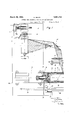
Fig. 1 illustrates diagrammatically one constructive embodiment of the invention in part;
Fig. 1a shows diagrammatically the additional part to Fig. 1;
Fig. 2 is an illustration of the optical sys tem of Figure 1;
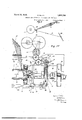
Fig. 3'is an elevation of the anti-duplicatmg system; v
Fig. 3a is a side elevational view of the apparatus shown in Fig. 3;.
Fig. 4 shows a mechanism for varying the rate of advance of the receiving apparatus.
Def or-mz'ng apparatus The document to be deformed is applied to cylinder 1 which is illuminated along a generatrix a over a width of one third of a mm. by means of any convenient optical system. In my preferred form of carrying out my invention, I use, to illuminate the generatrix a of cylinder 1, a lamp S and a cylindric lens L, as shown on Figures 1 and 2; a slit F is placed on the path of the luminous beam after reflexion on the cylinder 1, so as to give a plane beam P (Fig. 2) whose width is equal to that-of generatrix a, i. e. one third of a mm. This beam falls upon an oscillatipg mirror 35, which rejects the beam on an objective 0; this objective 0 concentrates the beam on a photographic film or paper applied to cylinder 6 which is enclosed in opaque chamber 7, 8 through which it is possible to obtain a punctual aperture, which is displaced along a given generatrix as will be explained hereinafter.
The mirror 35 is given a slow movement of small amplitude about an axis perpendicular to generatrix a.
Chamber 7, 8 is composed of two concentrio cylinders. Interior cylinder 7 is fixed in position and provided with a long tudinal slot 7'. Exterior cylinder 8 rotates at uniform speed about its axis and is provided with a. helicoidal slot 8 on one half of its periphery. The light reflected from mirror 35 traverses slots 7 and 8 and yields a punctiform beam at their point of intersection which falls upon the photo-sensitive. film or paper on cylinder 6 to give the deformed image used for transmission.-
The photographing of the line takes place during one half a turn of cylinder 8. During the other half turn (dead) the following operations occur: Photographic cylinder 6 is displaced angularly by predetermined amounts in a manner to be described further on; the movement is given by the main motor shaft M to a system which shall be hereinafter described and which gives the cylinder 6 Variable displacements. At the moment that cylinder 6 takes up a new position, cylinder 1 is rotated through a distance corresponding to one third of :1 mm. by means of a ratchet 2 and pawl 2 controlled by a solenoid 3 (electro) a cam 51 positioned on the main motor shaft M cutting off the current of the solenoid 3 after a brief interval (this assembly will be described in detail further on). During the exploration of the document applied to cylinder 1, which lasts only one revolution, cylinder 6 rotates through a number of turns which depend, obviously on the magnitude of. successive advances.
The small longitudinal bars, not shown,
which are used maintaining the photogaphic film or paper in place on cylinder 6 may move into position in front of slot 7 In such a case, a cam 52 breaks the circuit to the solenoid controlling cylinder 1 thus preventing further displacement of the latter and obviating the loss of non-photographed lines.
Mirror 35 is actuated by pinion 28 driving Maltese cross 25, simple or eccentric gear systems of the type 28, 27, 34, 39, being interposed to vary the character of its displacement. 1
Assembly for obtaining variable advanee 23 contacts with anyone of a plurality of pins 72 mounted on a rotatable support 24. At each oscillation of lever 21, support 24'is rotated by a mechanism to be described further on, so that the pins 39 mounted thereon are brought successively under lever 23. Ratchet Wheel 20 is thus displaced through distances varying with the height of the pins 10 on support 24. Rotation of 24 is efi'ected by means of the Maltese cross 25 driven from the main motor shaft by auxiliary shaft 29 and plate 26 carrying an extension.
Anti-duplicating system an example, to 3, 7, 11, 9, 13 teeth, occurring periodically in accordance with the number of pins on support 24. In order to be certain that all the lines on cylinder 6 are explored without any omission, the sum of the advances during any given period should be prime with the number of teeth on ratchet wheel 20. Secondly, certain generatrices would be repeated before arriving at the final line. But since any given generatrix can only be exposed once, means must be provided for preventing super-position of any pair of lines, i. e., an anti-duplicating system must be'employed.
Anti-duplicator 36 includes a circular crown provided with as many keys 41 as there are teeth on ratchet Wheel 20. Rotation of 36 brings an explorer 42 in front of some one key 41. At each stop, explorer 42 is displaced radially by a system of levers 37 controlled by a cam 37 driven by shaft m and, contacting with corresponding key 41, closes the circuit to solenoid 3. As soon as contact is established, a pusher 43, actuated in an analo ous manner b lever s stem 372 dis- O 7 places key 41 radially so that the latter is out of the range of explorer 42 during further explorations. During this period, cylinder 1 is arrested until a new photographic impression is to be made.
Inasmuch as the photo-sensitive film or paper on cylinder 6 should not be exposed while lines already recorded are being successively brought into line a second time for exposure, a shutter 19 is placed in the optical system between mirror 35 and cylinder 8, to prevent re-exposure. The shutter 19 is opened under the action of a solenoid 18 in series with solenoid 3 and closes automatically duringthe half (dead) revolution of cylinder 6.
Dividing system In order to explore a cylinder by thirds of a mm., wheels of disproportionated diameter would have to be used if a proper form of teeth is to be used i. e., about 2 mms. With wheels 100 mm. in diameter carrying 149 teeth, prime number, a peripheral advance of 1 mm. requires a 50 mm. cylinder.
The dividing system to be described efi'ects an exploration of one third of cylinder 1, the latter progressing by one third mm. by means of a reducing system of 1 to 3. Since the progression of cylinder 6 bandwise is difiicult to maintain correctly, the latter is driven directly without reduction i. e., by multiples of mms.
When the first 149 lines have been photographed, the 149 following are intercalated in the first third of a mm. left between the first; then the third and last series of 149 is inserted in the second third of the same interval.
The mechanism employed is simply a ratchet wheel 18 yielding a displacement of 4/3 of a tooth instead of 1/3. This mechanism enters into action only twice in the course of each cryptograph, once after the series of 149 lines, and the second time after the-second series. It is actuated by solenoid 19. After each series, all of keys 41 which are displaced radially, are moved back into operating position by a cable in external contact therewith and manually actuated.
Ree-composition. of the docwment In order to reconstitute the deformed document, an inverse operation is used: cylinder 1 supports the deformed document and cylinder 6, the photographic film or paper which receives the decoded document.
By referring to Fig. 1, it will be seen that cylinder 8 is rotated by pinions 9, 10, and is rotatably supported on yoke and roller 12 mounted in a casing 13 supported on said cylinder. Carriage 14 serves forthe rearward movement of cylinder assembly 7, 8, when cylinder 6 has to be charged with the photo-sensitive film or plate. Rotation on cylinder 8 is effected by plate 15.
Obviously, the action of the pins supported on support 24 may be complicated at will to vary the deformation in any way desired.
What I claim is:
1. The herein described method of secret the generatrices and putting them back in order at the receiving end so as to reconstitute the original document.
2. The herein described method of transmitting a document which consists in displacing the document in a predetermined way, projecting a band of light on the document, reflecting the band of light projected on the document onto a photosensitive surface being displaced in a different manner than the original document, developing and finishing the image on the photosensitive surface and transmitting the developed image thus obtained.
3. A method, as claimed in claim 2, including the step of displacing the transmitted image in the same wav as the said photosensitive surface was displaced, displacing 'an unexposed negative in the same manner as the original document, reflecting a light beam projected from said transmitted document onto said unexposed negative, and developing the image thus obtained.
4. An apparatus of the class described comprisingin combination a support adapted to carry the document to be transmitted, means for producing a deformed image of the exploration generatrices of the document by arbitrarily transmitting lines on a second support carrying a photo-sensitive surface and means for putting the generatrices.
6. An apparatus of the character described comprising in combination a rotatable cylinder adapted to carry the document to be transmitted, a cam, an electromagnet, a main motor shaft carrying the cam which during each turn closes a circuitactuating the electromagnet controlling the rotation of the rotatable cylinder, means for forming a deformed image of the exploration generat-rices of the document on a second support carrying a photo-sensitive surface and means for putting said generatrices in a variable order to render the same illegible.
7. An apparatus of the character described comprising in combination an electromagnetically actuated rotatable cylinder adapted to carry the document to be transmitted, a'main motor shaft, a cam supported by the main motor shaft for controlling the electromagnet, an optical system lighting the document supported by the said rotatable cylinder along a generatrix, means for forming a deformed image of the explorated'generatrix on a second cylinder carrying a photo-sensitive surface and means for putting the successive generatrices in a variable order to render the same illegible.
8. An apparatus of the class described comprising in combination a rotatable cylinder adapted to carry the document to be transmitted and actuated by an electro-magnet controlled by a cam supported by. the main motor shaft, an optical system comprising a luminous source and a cyllndric lens to concentrate the beam along ageneratrlx of the cylinder, means for forming a deformed image of the explorated generatrix on a second cylinder carrying a photo-sensitive surface and means for putting the successive generatrices in a variable order to render the same-illegible.
ing the beam along a generatrix of the cylinder, a slit, after the cylinder, giving a band of light reflected by an oscillating mirror on an objective which concentrates the said band on a generatrix of the second cylinder, means for Unmasking the said generatrix through a movable punctual aperture and means for putting the successive generatrices in a variable order to render the received document illegible.
10. An apparatus of the character described comprising in combination, a rotatable cylinder adapted to carry the document to be transmitted and being actuated by an electro-magnet which being controlled by a cam supported by the main motor shaft, an optical system comprising a luminous source and a cylindric lens concentrating the beam along a generatriz; of the cylinder, a slit after the cylinder, giving a band of light reflected by an oscillating mirror on an objective which concentrates the said band on a generatrix of the second cylinder, a cylindric case concentric with the second cylinder and composed of two concentric cylinders, interior cylinder fixed in position and provided with a longitudinal slot, and an exterior cylinder rotating at uniform speed about its axis and being provided with a helicoidal slot on one half of its periphery and means for putting the successive generatrices in a variable order to render the received document illegible.
11. Anapparatus of the character described, comprising in combination, an electromagnetically actuated rotatable cylinder adapted to carry the document to be transmitted, a main motor shaft, a cam supported second cylinder and composed of two concen-.
tric cylinders, an interior cylinder fixed in position and provided with a longitudinal slot and an exterior cylinder rotating at uniform speed about its axis and being provided with a helicoidal slot on one half of its periphery, further means for transmitting movement to the oscillating mirror of the main motor shaft to accomplish oscillation of the mirror during half a revolution of the cylindric case of the second cylinder and means for putting the successive generatrices in variable order to render the received document illegible.
12. An apparatus of the character de scribed comprising in combination an electromagnetically actuated rotatable cylinder adapted to carry the document to be transmitted, a main motor shaft, a cam supported by the main motor shaft for controlling the electromagnet, an optical system comprising the second cylinder, a cylindric case concentric with the second cylinder and composed of two concentric cylinders, an interior cylinder being fixed in position and provided with a longitudinal slot and an exterior cylinder rotating at uniform speed about its axis and being provided with a helicoidal slot on one half of its periphery, means for tran's uniting the movement of the motor shaft to an oscillating lever in two parts, one of which raises the second one, which falls back on. pimof different heights and controls the corresponding rotation of a wheel leading the said second cylinder, and means for causing successively, in the course of each oscillation, the presentation of the pins of different heights under the movable part of said lever.
13. An apparatus of the character described comprising in combination, an elec tromagnetically actuated rotatable cylinder adapted to carry the document to be transmitted, a main motor shaft, a cam supported by the main motor shaft for controlling the elcctromag'net, an optical system comprising a luminous source and a cylindric lens concentrating the beam along a generatrix of the cylinder. a slit giving a band of light reflected by an oscillating mirror on an objective which concentrates the said band on a generatrix of the second cylinder, a cylindrical case'concentric with said second cylinder and composed of two concentric cylinders, an interior cylinder fixed in position and provided with a longitudinal slot and an exterior cylinder rotating at uniform speed about its axis and provided with a helicoidal slot on one half of its periphery, means for transmitting the no movement of the motor shaft to an oscillating lever in two parts, oneof which raises the second one which falls back on pins of different heights and controls the corresponding rotation of a Wheel leading the said second cylinder, means for causing successively in the course of each oscillation, the presentation of the pins of different heights under the movable part of said lever, and a cam fitted on the shaft of said second cylinder closing the circuit of the electromagnet of the first cylinder and breaking it when the fixationbar of the photo-sensitive surface on the second cylinder falls in front of the luminous beam.
14. An apparatus of the character described comprising in combination an electromagnetically actuated rotatable cylinder adapted to carry the document to be transmitted, a main motor shaft, a cam supported 1 centrating the beam along a generatrix of the cylinder, a slit'giving' a band of light reflected by an oscillating mirror on an objective which concentrates the said band on a generatrix of the second cylinder,a cylindrical .case concentric with said second cylinder and composed of two concentric cylinders, an interior cylinder being fixed in position and provided with a longitudinal slot and an exterior cylinder rotating at uniform speed and provided with a helicoidal slot on one half of its periphery, means for transmitting the movement of the motor shaft to an oscillating lever in two parts, one of which raises the second one which falls back on pins of different heights, and controls the correspondingrotation of a wheel leading the said second cylinder, means for causing successively in the'course of each oscillation, the presentation of the pins of difierent heights under the movable part of said lever, a cam fitted on the shaft of said second cylinder, closing the circuit of the electro-magnet of the first cylinder and breaking it when the fixation bar of the photo-sensitive surface on the second cylinder falls in front of the luminous beam, and a cam fitted on the motor shaft and radially removing a lever mounted in a drum, which lever removes one of the keys mounted in this drum and closing the circuitof the electromagnet of the first cylinder. k
16. An apparatus of the character described comprising in combination an electromagnetically actuated rotatable cylinder adapted to carry the document to be transmitted, a main motor shaft, a cam supported by the main motor shaft for controlling said electromagnet, aluminous source, a cylindric lens concentrating the beam along a generatrix of the'cylinder, a slit giving a band of light reflected by an oscillating mirror on an objective which concentrates the said band on a generatrix of the second cylinder, a cylin-' dric case concentric with said second cylinder and comprising two concentric cylinders, an interior cylinder being fixed in position and provided with a longitudinal slot and an ex.- terior cylinder rotating at uniform speed about its axis and being provided with a helicoidal slot on one half of its periphery, means for transmitting the movement of the motor shaft to an oscillating lever one part of which raises the second one which falls back on pins of different heights and controls the corresponding rotation of a wheel leading the said second cylinder, means for causing successively the presentation of the pins ofdifierent heights under the movable part of said lever, a cam fitted on the shaft of said second cylinder closing and breaking the circuit of the electro-magnet of first cylinder,
a cam fitted on the motor shaft removing lever actuating keys mounted in a drum and closing the circuit of electro-magnet of first cylinder, means for bringing back in their rest position the said keys at the end of each operation, and a shutter actuated by an electromagnet in series with the electromagnet actuating the first cylinder, the displacement A of this shutter being simultaneous with the movement of said keys.
- EDOUARD BELIN,
Applications Claiming Priority (1)
| Application Number | Priority Date | Filing Date | Title |
|---|---|---|---|
| FR1851748X | 1929-04-26 |
Publications (1)
| Publication Number | Publication Date |
|---|---|
| US1851748A true US1851748A (en) | 1932-03-29 |
Family
ID=9681664
Family Applications (1)
| Application Number | Title | Priority Date | Filing Date |
|---|---|---|---|
| US446258A Expired - Lifetime US1851748A (en) | 1929-04-26 | 1930-04-22 | Method and apparatus for coding and decoding |
Country Status (1)
| Country | Link |
|---|---|
| US (1) | US1851748A (en) |
Cited By (6)
| Publication number | Priority date | Publication date | Assignee | Title |
|---|---|---|---|---|
| US2425076A (en) * | 1944-02-26 | 1947-08-05 | Rca Corp | Secret facsimile system |
| US2575442A (en) * | 1946-02-28 | 1951-11-20 | Times Facsimile Corp | Facsimile control mechanism for effecting curvilinear scanning or recording |
| US2707208A (en) * | 1945-03-31 | 1955-04-26 | Rca Corp | Secrecy facsimile system |
| US2967907A (en) * | 1952-06-02 | 1961-01-10 | Hogan Faximile Corp | Continuous facsimile scanning apparatus |
| US3130631A (en) * | 1959-11-23 | 1964-04-28 | Osaka Denkai Kogyo Kabushiki K | Photographic image transferring apparatus |
| US4414579A (en) * | 1979-12-28 | 1983-11-08 | International Business Machines Corporation | Information transmitting and receiving station utilizing a copier-printer |
-
1930
- 1930-04-22 US US446258A patent/US1851748A/en not_active Expired - Lifetime
Cited By (6)
| Publication number | Priority date | Publication date | Assignee | Title |
|---|---|---|---|---|
| US2425076A (en) * | 1944-02-26 | 1947-08-05 | Rca Corp | Secret facsimile system |
| US2707208A (en) * | 1945-03-31 | 1955-04-26 | Rca Corp | Secrecy facsimile system |
| US2575442A (en) * | 1946-02-28 | 1951-11-20 | Times Facsimile Corp | Facsimile control mechanism for effecting curvilinear scanning or recording |
| US2967907A (en) * | 1952-06-02 | 1961-01-10 | Hogan Faximile Corp | Continuous facsimile scanning apparatus |
| US3130631A (en) * | 1959-11-23 | 1964-04-28 | Osaka Denkai Kogyo Kabushiki K | Photographic image transferring apparatus |
| US4414579A (en) * | 1979-12-28 | 1983-11-08 | International Business Machines Corporation | Information transmitting and receiving station utilizing a copier-printer |
Similar Documents
| Publication | Publication Date | Title |
|---|---|---|
| US2594358A (en) | System and apparatus for selective photographing | |
| US1851748A (en) | Method and apparatus for coding and decoding | |
| US2298666A (en) | Apparatus for printing | |
| US3125812A (en) | Apparatus for decoding an encoded light image | |
| US2178379A (en) | Means for photographic type composing | |
| US1801458A (en) | Photographic apparatus | |
| US2747459A (en) | Photographic apparatus | |
| US2664038A (en) | Apparatus for type composition | |
| US3598484A (en) | Holographic method | |
| US3218945A (en) | Phototypesetting apparatus | |
| US3827063A (en) | Multilens photocomposing mechanism | |
| US2782678A (en) | Copying camera | |
| US3663101A (en) | Microfilm viewer-printer | |
| US3207051A (en) | Photographic type composing apparatus | |
| US2767628A (en) | Photographic composing apparatus | |
| US2201009A (en) | Apparatus for photographing documents | |
| US3064545A (en) | Printer | |
| US3643559A (en) | Photographic type-composing machine | |
| US3537365A (en) | Photographic printing apparatus | |
| US3273475A (en) | Photographic type composition device | |
| US3821753A (en) | Multifont photocomposing mechanism | |
| US2508650A (en) | Method and means of photography employing a scanning camera | |
| US3631774A (en) | Photocomposing apparatus with improved character recording apparatus and methods | |
| GB1242714A (en) | Improvements in or relating to photocomposing apparatus | |
| US1176147A (en) | Telegraphy. |