US1851743A - Process and apparatus for treating natural gas - Google Patents
Process and apparatus for treating natural gas Download PDFInfo
- Publication number
- US1851743A US1851743A US99008A US9900826A US1851743A US 1851743 A US1851743 A US 1851743A US 99008 A US99008 A US 99008A US 9900826 A US9900826 A US 9900826A US 1851743 A US1851743 A US 1851743A
- Authority
- US
- United States
- Prior art keywords
- column
- gasoline
- oil
- pressure
- vapor
- Prior art date
- Legal status (The legal status is an assumption and is not a legal conclusion. Google has not performed a legal analysis and makes no representation as to the accuracy of the status listed.)
- Expired - Lifetime
Links
Images
Classifications
-
- C—CHEMISTRY; METALLURGY
- C10—PETROLEUM, GAS OR COKE INDUSTRIES; TECHNICAL GASES CONTAINING CARBON MONOXIDE; FUELS; LUBRICANTS; PEAT
- C10G—CRACKING HYDROCARBON OILS; PRODUCTION OF LIQUID HYDROCARBON MIXTURES, e.g. BY DESTRUCTIVE HYDROGENATION, OLIGOMERISATION, POLYMERISATION; RECOVERY OF HYDROCARBON OILS FROM OIL-SHALE, OIL-SAND, OR GASES; REFINING MIXTURES MAINLY CONSISTING OF HYDROCARBONS; REFORMING OF NAPHTHA; MINERAL WAXES
- C10G5/00—Recovery of liquid hydrocarbon mixtures from gases, e.g. natural gas
- C10G5/04—Recovery of liquid hydrocarbon mixtures from gases, e.g. natural gas with liquid absorbents
-
- C—CHEMISTRY; METALLURGY
- C10—PETROLEUM, GAS OR COKE INDUSTRIES; TECHNICAL GASES CONTAINING CARBON MONOXIDE; FUELS; LUBRICANTS; PEAT
- C10G—CRACKING HYDROCARBON OILS; PRODUCTION OF LIQUID HYDROCARBON MIXTURES, e.g. BY DESTRUCTIVE HYDROGENATION, OLIGOMERISATION, POLYMERISATION; RECOVERY OF HYDROCARBON OILS FROM OIL-SHALE, OIL-SAND, OR GASES; REFINING MIXTURES MAINLY CONSISTING OF HYDROCARBONS; REFORMING OF NAPHTHA; MINERAL WAXES
- C10G2300/00—Aspects relating to hydrocarbon processing covered by groups C10G1/00 - C10G99/00
- C10G2300/10—Feedstock materials
- C10G2300/1025—Natural gas
-
- Y—GENERAL TAGGING OF NEW TECHNOLOGICAL DEVELOPMENTS; GENERAL TAGGING OF CROSS-SECTIONAL TECHNOLOGIES SPANNING OVER SEVERAL SECTIONS OF THE IPC; TECHNICAL SUBJECTS COVERED BY FORMER USPC CROSS-REFERENCE ART COLLECTIONS [XRACs] AND DIGESTS
- Y10—TECHNICAL SUBJECTS COVERED BY FORMER USPC
- Y10S—TECHNICAL SUBJECTS COVERED BY FORMER USPC CROSS-REFERENCE ART COLLECTIONS [XRACs] AND DIGESTS
- Y10S206/00—Special receptacle or package
- Y10S206/80—Chewing gum
Definitions
- This invention relates to an improved method and apparatus for makingfinished gasoline from natural gas, and more particularly to a novel method and apparatus for stripping gasoline from absorbent oil and rectifying said gasoline.
- the primary object of the present invention is to improve this system, and to this end I utilize the vapor pressure of the absorbingr oil enriched by the gasoline vapors, to build desired pressure in the distilling apso that proper rectification of the light gases can be obtained without resort to extremely low temperature cooling mediums in the reflux condensers, or extremely high compression in the compressors.
- the distilling apparatus itself becomes a compressor, in which the heat is in part converted to work in compressing, and better thermal efficiency is realized in this conversion of heat to work than is accomplished by mechanical means.
- vapor pressure set up by the mixture of absorbent oil and vapors undergoing treatment and it is also possible to considerably increase the operating pressure through the selection lof an absorbent. medium of higher vapor pressure.
- ity is necessary to maintain a pressure through utilization of the vapor pressure of the mixture of absorbing oil and vapors, so that the gasoline to be recovered exists in the liquid phase at normal cooling water temperatures.
- Another object of my invention is to provide a novel method of securing the necessary pressure for proper rectification of the light gases, so that said gases may be rectified under ordinary cooling water temperatures.
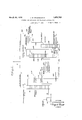
- Fig. l is a diagrammatic view of my improved apparatus employed in carrying out the new process.
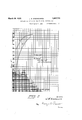
- Fig. 2 shows graphs illustrating the vapor pressures set up at different temperatures, in n treating certain substances.
- 1 designates the pipe for the incoming raw natural gas, which if it is not under sullicient pressure, is discharged int-o a compressor 2, the latter forcing the compressed gasthrough a pipe 3 into the lower end of an absorbing tower 4, which is preferably of the bubble plate type.
- the preheated mixture of oil and gasoline leaves the heat ex-changerby way of pipe 11 and enters a pump 12, which forces the mixture through the main heating element 13, from which it is inally discharged by pipe 14 into the rectifier-stripper 15.
- the mixture undergoes fractional distillation, gasoline vapors passing upwardly and the condensates of the absorbent oil Vmoving downwardly.
- This action is facilitated by the refiux condenser 16, which functions to condense a portion of the vapor, and this condensate is fed hack into the column by way ofipipe 17.
- TheY heatkfor this rectifier may be provided by an suitable means but for-economic reasons, prefer to heat the same in the following manner.
- the absorbent oil in its heated condition leaves the bottom of the tower 15 ⁇ by way of pipe 20 and passes into a coil 21 arranged within the lowerportion of the rectifier 19.V
- the absorbent oil leaves the coil 21 by pipe- 22 from which it enters a pump 23 and. is forced through the heat exchanger 10, then through apipe 24, water cooled coil 25, and pipe 26 back. into the top of the absorber tower 4.
- Valves 27 and 28 are provided to regulate Y the flowof the oil through-'the coil 21, and
- a icy-pass pipe 29 is arranged" between'the pipes 20 and 22 for bypassing some or all of the stripped absorbent oil ifl necessary.
- a valve 30 is arranged inthe by-pass 29.
- the rectifier 19 also operates under pressure,Y and the lightest vvapors pass out of the top of the column through a pipe 31 and-enter Uncondensed gases pass from the condenser32 by way of pipe 33, pressure regulating valve 34, and pipe 35, into the discharge line 7 Condensate from the condenser 32' passes through pipe 36 and is reintroduced into the upper'portion of the rectifier..
- the finished gasoline is removed byV pipec37froin the lower portion of the rectifier 19. f
- the compressor and pumps are so actuated as to facilitate the maintenance of certain pressures, and the pressure regulating valves are also set to keep the desired pressures in the various points of the apparatus.
- the enriched absorbing oil is moved lthrough the heat exchanger 10, by means of the initial pressure in the system, and then this enriched oil is forced by the pump 12 through the heating element 13.
- This pump forces the preheated enriched oil into thetower 15, which is also of the bubblecap plate type.
- the upper portion of this stripping column serves as a rectifier and is equipped with the reflux c0ndenser or heat'exchanger 16, in which a portion of the vapor leaving the column is con densed andl returned to the head of the column.
- the uncondensed vapor from the member 16 passes through pipe 18 and enters the rectifier 19 slightly below the middle 0f the latter. Vapor leaving the top of the column 19 enters the condenser 32 from which all the condensate is'returned to the top of the tower 19 as a reflux.
- the uncondensed or dry gas passes out by way of the valve 34;, while the finished gasoline, stabilized to the desired degree, is discharged from the lower end of the column 19.
- raw natural gasA enters the plant through the pipe 1, and passes to the inlet of the compresso-r.
- This gas is Vcompressed up to about 30 or L10 lbs. pressure above atmospheric, and discharged into the bottom of the absorption tower Ll, w 1ere the uprising gases are scrubbed with lean absorption oil entering the tower through the conduit 2G, at about TOO F. temperature.
- the gases leaving the tower through the pipe 5 andl pressure regulating valve 6, pass direct to apoint of consumption, and they test from Zero t'oabout one-quarter gallon gasoline contentk per M..cubic feet by the charcoal method.
- the enriched absorption oil leaving the bottom of the absorber through the pipe 9, passes through the heat exchanger counter current to the lean absorption ol, and the temperature on this heat exchanger averages about as follows:
- Enriched absorption oil leaving the heat exchanger through the conduit 11 enters the pump 12 from which it is discharged into the heatingr coil 13 under a pressure of 1i' to 250 lbs. rl'his coil is heated from 500 to 600 F.,
- Tower 15 is retluxed by a condensate from the water cooled condenser 16.
- the condensate enters the tower 15 at a temperature of about 70 to 80 F., and the temperature maintained at the top of this tower is about 7 5 to 2000 F., such temperature depending upon the end point of the gasoline that is being recovered.
- he temperature at the bottom of the tower 15 averages about 500 to 550 F.
- Gases remaining uncondensed from the reflux condenser 16 pass to the second column 1), and enter this column a few trays from the bottom.
- This tower operates at a temperature of around 8O to 125O F. at the top, and about 275 to y30()o F. at the bottom, and heat is supplied by passing the lean absorption oil from the 15 through the coil 21.
- the vapor pressure of the enriched absorbing oil is utilized to build up any desired pressure on the distilling apparatus so that the proper rectification of ⁇ the light gases can be obtained without the necessity of working under extremely low cooling temperatures or using after compressors.
- the still 15 itself becomes a compressor in which the heat is in part converted to work in compressing, and better thermal efficiency is realized in this conversion of heat to work than can be obtained by mechanical means.
- What I claim ters Patent is 1.
- gasoline vapor is extracted from gas by the use of absorbent oil, passing the vapor enriched oil in heated condition and under super-atmospheric pressure into a first rectifying column, passing gasoline vapor from the top of said column to a second rectifying column, releasing uncondensed gases from the second column through a pressure regulating valve, utilizing said valve to maintain pressure and utilizing the vapor pressure of the enriched absorbing oil to build up suiicient pressure in both columns to sharply fractionate'the materials undergoing treatment at relatively high super-atmospheric temperatures.
- a process for separating gasoline from absorbent oil and rectifying said gasoline consisting in charging a heated mixture of absorbent oil and gasoline vapors under pressure into a rectifying column, separating oil from the gasoline vapors in said column, passing the gasoline vapors to a second rectifying column, passing vapors from the second column through a reflux condenser, pass ing condensate from the refluxy condenser back to the top of the second column, disnd desire to secure by Letwithin both of said columns,
- a process of the character described consisting in charging gasoline vapor en.- riched absorbent oil under pressure and in heated condition into a first rectifying column, passing apors from the top of said column into a reflux condenser, returning condensate from said condenser to the upper portion of said column, passinguncondensed vapor from the condenser to a second rectifying column, discharging ⁇ the denuded ⁇ absorbent oil from the lower portion of said first column., passing vapor from the upper portion of the second.
- rectifying a mixture of hydrocarbon vapors and absorbent oil tosharply separate the vapors from the oil subsequently rectifying said vapors to separate the same into al gaseous fraction and a liquid frac-tion, and utilizing the vapor pressureof the mixture of oil and vapors to build up a predetermined pressure during said rectification treatments.
- An apparatus for recovering gasoline including ⁇ a first rectifying column, means for pumping', heating and feeding a mixture of absorbent oil and gasoline vapors into said rectifying column, a. reiiux condenser arranged at the upper portion of said column, means for conducting vapor from the toprof said column to said reflux condenser,.means for returning condensate from said condenser to the upper portion of said column, a second rectifying column, means for leading vapor from the reflux condenser to the second column, means for discharging vapor from the top of the second column, a second reflux condenser to receive the vapor discharged from the top of the second column, means for returning condensate from the second condenser to the upper portion of the second column, means including a pressure regulating valve for discharging uncondensed gases from the second condenser, and means for removing finished gasoline from the lower portion of the second column.
- An apparatus for recovering gasoline from gas including a. first rectifying column, a heat exchanger, means for feeding vapor enriched absorbent oil through said heat exchanger, means for pumping, heating and feeding the enriched absorbent oil from the heat exchanger into said rectifying column, a second'rectifying column, means for feeding gasoline vapor from the top of the lirst rectifying column to the intermediate portion of the second rectifying column, a reflux condenser arranged at the upper portion of the second column, means including a pressure regulating valve for discharging uncondensed gases from said condenser, means for feeding condensate from the condenser into the upper portion of the second column, and means for discharging linishedl gasoline from the lower portion of the second rectifying column.
- apparatus as claimed in claim 9, including a heating coil arranged in the lower portion of the second column, and means for feeding denuded absorbent oil from the first column through said coil.
Landscapes
- Chemical & Material Sciences (AREA)
- Oil, Petroleum & Natural Gas (AREA)
- Engineering & Computer Science (AREA)
- Chemical Kinetics & Catalysis (AREA)
- General Chemical & Material Sciences (AREA)
- Organic Chemistry (AREA)
- Production Of Liquid Hydrocarbon Mixture For Refining Petroleum (AREA)
Description
March'29, 1932. .1. M. wADswoRTH 1,851,743
PROCESS AND APPARATUS FOR TREATING' NATURAL GAS Filed April l, 1926 2 Sheets-Sheet l n ATTORNEY.
March 29, 1932. J, M, WADSWORTH 1,851,743
PRocEss AND APPARATUS Foa TREATING NATURAL GAs Filed April, 1926 2 sheets-sheet 2 Tj- E gvmw/nffol of/WadWw-ff i up any B. gravity gas oil, and a `blend of Patented Mar. 29, 1932 PATENT oFFicE JAMES M. WADSWORTH, OF SAND SPRINGS, OKLAHOMA PROCESS AND APPARATUS FORTREATING NATURAL GAS Application led April 1,
This invention relates to an improved method and apparatus for makingfinished gasoline from natural gas, and more particularly to a novel method and apparatus for stripping gasoline from absorbent oil and rectifying said gasoline.
It is customary in the natural gasoline industry, to pass natural gas through a tower and to contact liquid absorbent, such as oil; to subsequently t distill the gasoline vapors from the absorbent oil, and to finally rctify the gasoline, in order to remove propane, ethane and methane, by resorting to extremely low cooling temperatures or the use of an after compresser.
The primary object of the present invention is to improve this system, and to this end I utilize the vapor pressure of the absorbingr oil enriched by the gasoline vapors, to build desired pressure in the distilling apso that proper rectification of the light gases can be obtained without resort to extremely low temperature cooling mediums in the reflux condensers, or extremely high compression in the compressors. In my system, the distilling apparatus itself becomes a compressor, in which the heat is in part converted to work in compressing, and better thermal efficiency is realized in this conversion of heat to work than is accomplished by mechanical means. v
The graphs, made a part of this specification, illustrate the vapor pressure set up at different temperatures by an ordinary 34 this gas oil with five per cent of casing head gasoline to the gas oil, very considerably raises the vapor pressure for any given temperature, and that sufficient pressure can be obtained paratus,
Athrough the use of this phenomena for ,the
rectification of gasoline vapors before cracking temperature of the mixture is reached. It has been found in practical operation that the fractionation of these gasoline rvapors i from the uncondensible gases can bevery satisfactorily done at pressures not 1n excess of Q00 lbs. gauge, with ordinary cooling water conditions. In the method. as described, it is possible to vary the operating pressure of the system, of course, through the range of the gas in said tower with a 1926; Serial N0. 99,608.
vapor pressure set up by the mixture of absorbent oil and vapors undergoing treatment, and it is also possible to considerably increase the operating pressure through the selection lof an absorbent. medium of higher vapor pressure. In operating the system, ity is necessary to maintain a pressure through utilization of the vapor pressure of the mixture of absorbing oil and vapors, so that the gasoline to be recovered exists in the liquid phase at normal cooling water temperatures.
From the foregoing it will be understood that another object of my invention is to provide a novel method of securing the necessary pressure for proper rectification of the light gases, so that said gases may be rectified under ordinary cooling water temperatures. With ythe system which I have devised, it is possible to retain a relatively large percentage of butane in the rectified gasoline, so that the latter may be used for blending, or I may eliminate substantially all of thebutane, so as to obtain a finished gasoline practically free of butane and lighter gases. and this gasoline may be sold directly to filling stations without resorting to blending. y
With the foregoing obj ccts outlined and with other objects in view which will appear as the description proceeds, the invention consists in the novel features hereinafter described in detail and illustrated in part in the accompanying drawings, and more particularly-pointed out in the appended claims.l
. In the drawings:
Fig. l is a diagrammatic view of my improved apparatus employed in carrying out the new process.
Fig. 2 shows graphs illustrating the vapor pressures set up at different temperatures, in n treating certain substances.
In the drawings, 1 designates the pipe for the incoming raw natural gas, which if it is not under sullicient pressure, is discharged int-o a compressor 2, the latter forcing the compressed gasthrough a pipe 3 into the lower end of an absorbing tower 4, which is preferably of the bubble plate type. The denudcd or lean gas which leaves the top of the tower b v pipe 5, passes through a pressure regulating valve 6 into the discharge tained in the tower 4.
The absorbent oil containing the absorbed gasoline vapors which it has extracted from the gas, leaves the lower end of the tower by way of pipe 9' and passes through a heat exchanger 10, which is heated by the absorbent oil after the latter has left the distilling column, which will be described hereinafter. The preheated mixture of oil and gasoline leaves the heat ex-changerby way of pipe 11 and enters a pump 12, which forces the mixture through the main heating element 13, from which it is inally discharged by pipe 14 into the rectifier-stripper 15. This rectifier-stripperis a combination of a stripping still and a rectifying column, and at its upper end it is provided with a reflux condenser or heat exchanger` 16. The heated mixture of absorbent Voil and gasolineenters the column 115 under pressure and is maintainedV under pressure in this column. In the column the mixture undergoes fractional distillation, gasoline vapors passing upwardly and the condensates of the absorbent oil Vmoving downwardly. This action is facilitated by the refiux condenser 16, which functions to condense a portion of the vapor, and this condensate is fed hack into the column by way ofipipe 17. The gasoline vapor which is not condensed in` 16, passes'throughpipe 18 and entiers the rectifier 19. TheY heatkfor this rectifier may be provided by an suitable means but for-economic reasons, prefer to heat the same in the following manner. The absorbent oil in its heated condition leaves the bottom of the tower 15`by way of pipe 20 and passes into a coil 21 arranged within the lowerportion of the rectifier 19.V The absorbent oil leaves the coil 21 by pipe- 22 from which it enters a pump 23 and. is forced through the heat exchanger 10, then through apipe 24, water cooled coil 25, and pipe 26 back. into the top of the absorber tower 4.
' a condenser 32.
a icy-pass pipe 29 is arranged" between'the pipes 20 and 22 for bypassing some or all of the stripped absorbent oil ifl necessary. A valve 30 is arranged inthe by-pass 29.
The rectifier 19, also operates under pressure,Y and the lightest vvapors pass out of the top of the column through a pipe 31 and-enter Uncondensed gases pass from the condenser32 by way of pipe 33, pressure regulating valve 34, and pipe 35, into the discharge line 7 Condensate from the condenser 32' passes through pipe 36 and is reintroduced into the upper'portion of the rectifier.. The finished gasoline is removed byV pipec37froin the lower portion of the rectifier 19. f
In. operation, the compressor and pumps are so actuated as to facilitate the maintenance of certain pressures, and the pressure regulating valves are also set to keep the desired pressures in the various points of the apparatus. The enriched absorbing oil is moved lthrough the heat exchanger 10, by means of the initial pressure in the system, and then this enriched oil is forced by the pump 12 through the heating element 13. This pump forces the preheated enriched oil into thetower 15, which is also of the bubblecap plate type. As before stated, the upper portion of this stripping column serves as a rectifier and is equipped with the reflux c0ndenser or heat'exchanger 16, in which a portion of the vapor leaving the column is con densed andl returned to the head of the column. The uncondensed vapor from the member 16 passes through pipe 18 and enters the rectifier 19 slightly below the middle 0f the latter. Vapor leaving the top of the column 19 enters the condenser 32 from which all the condensate is'returned to the top of the tower 19 as a reflux. The uncondensed or dry gas passes out by way of the valve 34;, while the finished gasoline, stabilized to the desired degree, is discharged from the lower end of the column 19.
In a specific example, raw natural gasA enters the plant through the pipe 1, and passes to the inlet of the compresso-r. This gas is Vcompressed up to about 30 or L10 lbs. pressure above atmospheric, and discharged into the bottom of the absorption tower Ll, w 1ere the uprising gases are scrubbed with lean absorption oil entering the tower through the conduit 2G, at about TOO F. temperature. The gases leaving the tower through the pipe 5 andl pressure regulating valve 6, pass direct to apoint of consumption, and they test from Zero t'oabout one-quarter gallon gasoline contentk per M..cubic feet by the charcoal method.
The completeness of the gasoline removal on tl'ese gases depends, of Course, upon the amount of absorption oilV used per foot of gas, and when properly supervised, the gases can practically be denuded of all gasoline. The lean absorption oil entering the absorption tower through line 26, tests:
Gravity 32h34; InitiaL 300409 over at 41,0 Max. 1%
The enriched absorption oil leaving the bottom of the absorber through the pipe 9, passes through the heat exchanger counter current to the lean absorption ol, and the temperature on this heat exchanger averages about as follows:
Enriched oil, in at 'T0 and out at 30G-375.
Lean oil, in at 500-550 and out at 15G-175.
Enriched absorption oil leaving the heat exchanger through the conduit 11, enters the pump 12 from which it is discharged into the heatingr coil 13 under a pressure of 1i' to 250 lbs. rl'his coil is heated from 500 to 600 F.,
y column and the hot oil and' vapors from this coil enter the rectiying tower 15 near the bottom of the tower, as the lower portion of this tower is used for stripping purposes. Tower 15 is retluxed by a condensate from the water cooled condenser 16. The condensate enters the tower 15 at a temperature of about 70 to 80 F., and the temperature maintained at the top of this tower is about 7 5 to 2000 F., such temperature depending upon the end point of the gasoline that is being recovered. he temperature at the bottom of the tower 15 averages about 500 to 550 F. Gases remaining uncondensed from the reflux condenser 16, pass to the second column 1), and enter this column a few trays from the bottom. This tower operates at a temperature of around 8O to 125O F. at the top, and about 275 to y30()o F. at the bottom, and heat is supplied by passing the lean absorption oil from the 15 through the coil 21.
Gases leaving the top of the tower 19, pass through the linie 31, and a condenser 32. and everything that will condense at o F., is condensed in the coil 32. Uncondensed gases from this coil are vented through valve 34, and everything` that condenses is returned to the tower through the line 36.
During such operation, the pressure on the two towers is carried between 50 and 7 5 lbs. However, it will be evident that with the temperature of the condenser 32 at 'TOO F., and a pressure around 50 lbs., no propane is reiiuxed, but a considerable amount of butane is returned to the column 19, through the pipe 36.. The gasoline made under the conditions stated, tested:
Gravity 85-9() Initial 50-70 End point 250-350 Recovery 95 Color 25%() Saybolt.
It will be noted that this initial boiling` point would indicate the gasoline contained considerable butane, and at the same time, had a recovery of 95%, so that it was a stable product. I would like to emphasize, however, tl at in operating', as above stated, the pressure carried on the fractionating towers 15, 19, is not as high as is desirable in producing a gasoline containing all the recoverable butane. On the other hand, if one wishes to make a gasoline that is free of butane, the columns 15 and 19 will be run somewhat lower pressures. Rutane tree gasoline is used at the presenttime for aviation purposes.
By properly controlling the pressure on the system for any cooling` water condition, it is possible to make a gasoline in the tower 19 which will contain, in addition to hexane and pentane. all or most of the butane, and at the same time. to sharply ractionate out 'the propane. It is equally kpossible to make a gasoline containing hexane and pentane from which all the butano and propane has been separated.
From the above it may be understood, in my improved system the vapor pressure of the enriched absorbing oil is utilized to build up any desired pressure on the distilling apparatus so that the proper rectification of `the light gases can be obtained without the necessity of working under extremely low cooling temperatures or using after compressors. The still 15 itself becomes a compressor in which the heat is in part converted to work in compressing, and better thermal efficiency is realized in this conversion of heat to work than can be obtained by mechanical means.
It is believed that the foregoing disclosure will enable those skilled in the art to construct my apparatus or carry out my process, and I am aware that changes may be made in details disclosed without departing from the spirit of the invention as expressed in the claims.
What I claim ters Patent is 1. In a gasoline recovery process wherein gasoline vapor is extracted from gas by the use of absorbent oil, passing the vapor enriched oil in heated condition and under super-atmospheric pressure into a first rectifying column, passing gasoline vapor from the top of said column to a second rectifying column, releasing uncondensed gases from the second column through a pressure regulating valve, utilizing said valve to maintain pressure and utilizing the vapor pressure of the enriched absorbing oil to build up suiicient pressure in both columns to sharply fractionate'the materials undergoing treatment at relatively high super-atmospheric temperatures.
2. In a process for separating gasoline from absorbent oil and rectifying said gasoline, rectifying a mixture of absorbent oil and gasoline under super-atmospheric pressure to separate the gasoline vapors from the oil, thenrectifying the gasoline vapors to separate lighter gases therefrom and maintaining a predetermined super-atmospheric pressure during the said rectifications by utilizing the vapor pressure of the enriched absorbing oil.
3'. A process for separating gasoline from absorbent oil and rectifying said gasoline, consisting in charging a heated mixture of absorbent oil and gasoline vapors under pressure into a rectifying column, separating oil from the gasoline vapors in said column, passing the gasoline vapors to a second rectifying column, passing vapors from the second column through a reflux condenser, pass ing condensate from the refluxy condenser back to the top of the second column, disnd desire to secure by Letwithin both of said columns,
changing uncondensed gas from the reflux condenser through a pressure regulating valve, discharging gasoline from the second column, and utilizing the vapor pressure of theenriched absorbing oil to build up a predetermined super-atmospheric pressure in saidI columns.
4l. A process of the character described consisting in charging gasoline vapor en.- riched absorbent oil under pressure and in heated condition into a first rectifying column, passing apors from the top of said column into a reflux condenser, returning condensate from said condenser to the upper portion of said column, passinguncondensed vapor from the condenser to a second rectifying column, discharging` the denuded` absorbent oil from the lower portion of said first column., passing vapor from the upper portion of the second. column to second reflux condenser, discharging uncondensed gases from the second condenser through a pressure regulating valve, passing' condensate from the second condenser into the upper portion of the second column, and discharging finished gasoline from the lower portion of the second column.
5. A process as claimed in claim 4, in which the denuded absorbent oil in heated condition is passed from the first column through the lower portionof the second column to furnish the heat for `rectification within the second column 6. In a process` of the character described, rectifying a mixture of hydrocarbon vapors and absorbent oil tosharply separate the vapors from the oil, subsequently rectifying said vapors to separate the same into al gaseous fraction and a liquid frac-tion, and utilizing the vapor pressureof the mixture of oil and vapors to build up a predetermined pressure during said rectification treatments.
7. An apparatus for recovering gasoline including` a first rectifying column, means for pumping', heating and feeding a mixture of absorbent oil and gasoline vapors into said rectifying column, a. reiiux condenser arranged at the upper portion of said column, means for conducting vapor from the toprof said column to said reflux condenser,.means for returning condensate from said condenser to the upper portion of said column, a second rectifying column, means for leading vapor from the reflux condenser to the second column, means for discharging vapor from the top of the second column, a second reflux condenser to receive the vapor discharged from the top of the second column, means for returning condensate from the second condenser to the upper portion of the second column, means including a pressure regulating valve for discharging uncondensed gases from the second condenser, and means for removing finished gasoline from the lower portion of the second column.
8. An apparatus as claimed in claim 7, including a heating coil arranged in the lower portion of the second column, and means for feeding denuded absorbent oil from the first column to said coil.
9. An apparatus for recovering gasoline from gas, including a. first rectifying column, a heat exchanger, means for feeding vapor enriched absorbent oil through said heat exchanger, means for pumping, heating and feeding the enriched absorbent oil from the heat exchanger into said rectifying column, a second'rectifying column, means for feeding gasoline vapor from the top of the lirst rectifying column to the intermediate portion of the second rectifying column, a reflux condenser arranged at the upper portion of the second column, means including a pressure regulating valve for discharging uncondensed gases from said condenser, means for feeding condensate from the condenser into the upper portion of the second column, and means for discharging linishedl gasoline from the lower portion of the second rectifying column.
l0. .ein apparatus as claimed in claim 9, including a heating coil arranged in the lower portion of the second column, and means for feeding denuded absorbent oil from the first column through said coil.
In testimony whereof I affix my signature.
JAMES lvl. WADSWVORTH.
CII
Priority Applications (1)
| Application Number | Priority Date | Filing Date | Title |
|---|---|---|---|
| US99008A US1851743A (en) | 1926-04-01 | 1926-04-01 | Process and apparatus for treating natural gas |
Applications Claiming Priority (1)
| Application Number | Priority Date | Filing Date | Title |
|---|---|---|---|
| US99008A US1851743A (en) | 1926-04-01 | 1926-04-01 | Process and apparatus for treating natural gas |
Publications (1)
| Publication Number | Publication Date |
|---|---|
| US1851743A true US1851743A (en) | 1932-03-29 |
Family
ID=22271996
Family Applications (1)
| Application Number | Title | Priority Date | Filing Date |
|---|---|---|---|
| US99008A Expired - Lifetime US1851743A (en) | 1926-04-01 | 1926-04-01 | Process and apparatus for treating natural gas |
Country Status (1)
| Country | Link |
|---|---|
| US (1) | US1851743A (en) |
Cited By (4)
| Publication number | Priority date | Publication date | Assignee | Title |
|---|---|---|---|---|
| US2547970A (en) * | 1948-02-28 | 1951-04-10 | Phillips Petroleum Co | Controlling heating valve of natural gas |
| US2564791A (en) * | 1947-06-26 | 1951-08-21 | Phillips Petroleum Co | Method for maintaining heating value of a fuel gas |
| US2726191A (en) * | 1955-03-24 | 1955-12-06 | Continental Oil Co | Processing raw natural gas to recover gaseous and gasoline hydrocarbons |
| US3402124A (en) * | 1966-03-16 | 1968-09-17 | Universal Oil Prod Co | Plural stage distillation with bottoms stream and side stream column heat exchange |
-
1926
- 1926-04-01 US US99008A patent/US1851743A/en not_active Expired - Lifetime
Cited By (4)
| Publication number | Priority date | Publication date | Assignee | Title |
|---|---|---|---|---|
| US2564791A (en) * | 1947-06-26 | 1951-08-21 | Phillips Petroleum Co | Method for maintaining heating value of a fuel gas |
| US2547970A (en) * | 1948-02-28 | 1951-04-10 | Phillips Petroleum Co | Controlling heating valve of natural gas |
| US2726191A (en) * | 1955-03-24 | 1955-12-06 | Continental Oil Co | Processing raw natural gas to recover gaseous and gasoline hydrocarbons |
| US3402124A (en) * | 1966-03-16 | 1968-09-17 | Universal Oil Prod Co | Plural stage distillation with bottoms stream and side stream column heat exchange |
Similar Documents
| Publication | Publication Date | Title |
|---|---|---|
| US3292380A (en) | Method and equipment for treating hydrocarbon gases for pressure reduction and condensate recovery | |
| US2603310A (en) | Method of and apparatus for separating the constituents of hydrocarbon gases | |
| JPS5817191A (en) | Recovery of condensible hydrocarbon from natural gas | |
| US3568457A (en) | Separation of propane and propylene by distillation | |
| US2468750A (en) | Method of separating hydrocarbons | |
| US3320754A (en) | Demethanization in ethylene recovery with condensed methane used as reflux and heat exchange medium | |
| US2519344A (en) | Adsorption process | |
| US2428521A (en) | Recovery of ethane and gasoline from natural gas | |
| US2487147A (en) | Fractionating methane and ethane from hydrocarbon mixtures | |
| US2250949A (en) | Process for the separation of hydrocarbons from gases containing them | |
| US2187631A (en) | Method of refining hydrocarbons | |
| US1851743A (en) | Process and apparatus for treating natural gas | |
| US2303609A (en) | Crude oil conditioning and separating process | |
| US1429175A (en) | Process of treating natural gas and product thereof | |
| US2663669A (en) | Method of stabilizing raw gasoline | |
| US2355589A (en) | Method of recovery of light hydrocarbons | |
| US2222276A (en) | Apparatus and a process for the recovery of gasoline from cracked petroleum hydrocarbons | |
| US2781293A (en) | Absorption recovery of hydrocarbons | |
| US2943041A (en) | Processing of steam-cracked naphtha light end products | |
| US3188287A (en) | Oil absorption process | |
| US2117548A (en) | Process of extracting and recovering volatile hydrocarbons from hydrocarbon gases | |
| US2168316A (en) | Distillation and fractionation process and apparatus | |
| US2168683A (en) | Absorption process | |
| US3236029A (en) | Recovery of hydrocarbons | |
| US2059494A (en) | Method of rectification |