US1851740A - Apparatus for preventing adhesion by frosting - Google Patents
Apparatus for preventing adhesion by frosting Download PDFInfo
- Publication number
- US1851740A US1851740A US473970A US47397030A US1851740A US 1851740 A US1851740 A US 1851740A US 473970 A US473970 A US 473970A US 47397030 A US47397030 A US 47397030A US 1851740 A US1851740 A US 1851740A
- Authority
- US
- United States
- Prior art keywords
- ice making
- receptacle
- mat
- compartment
- frost
- Prior art date
- Legal status (The legal status is an assumption and is not a legal conclusion. Google has not performed a legal analysis and makes no representation as to the accuracy of the status listed.)
- Expired - Lifetime
Links
- 239000004744 fabric Substances 0.000 description 6
- 239000007788 liquid Substances 0.000 description 3
- 239000002184 metal Substances 0.000 description 3
- 229910052751 metal Inorganic materials 0.000 description 3
- 238000012216 screening Methods 0.000 description 3
- XEEYBQQBJWHFJM-UHFFFAOYSA-N Iron Chemical compound [Fe] XEEYBQQBJWHFJM-UHFFFAOYSA-N 0.000 description 2
- 230000008014 freezing Effects 0.000 description 2
- 238000007710 freezing Methods 0.000 description 2
- 239000000463 material Substances 0.000 description 2
- 229910000906 Bronze Inorganic materials 0.000 description 1
- RYGMFSIKBFXOCR-UHFFFAOYSA-N Copper Chemical compound [Cu] RYGMFSIKBFXOCR-UHFFFAOYSA-N 0.000 description 1
- 241001547070 Eriodes Species 0.000 description 1
- 239000010974 bronze Substances 0.000 description 1
- 238000004140 cleaning Methods 0.000 description 1
- 230000005494 condensation Effects 0.000 description 1
- 238000009833 condensation Methods 0.000 description 1
- 238000010276 construction Methods 0.000 description 1
- 229910052802 copper Inorganic materials 0.000 description 1
- 239000010949 copper Substances 0.000 description 1
- 230000003247 decreasing effect Effects 0.000 description 1
- ALKZAGKDWUSJED-UHFFFAOYSA-N dinuclear copper ion Chemical compound [Cu].[Cu] ALKZAGKDWUSJED-UHFFFAOYSA-N 0.000 description 1
- 229910052742 iron Inorganic materials 0.000 description 1
- 229920000136 polysorbate Polymers 0.000 description 1
- 239000003507 refrigerant Substances 0.000 description 1
Images
Classifications
-
- F—MECHANICAL ENGINEERING; LIGHTING; HEATING; WEAPONS; BLASTING
- F25—REFRIGERATION OR COOLING; COMBINED HEATING AND REFRIGERATION SYSTEMS; HEAT PUMP SYSTEMS; MANUFACTURE OR STORAGE OF ICE; LIQUEFACTION SOLIDIFICATION OF GASES
- F25C—PRODUCING, WORKING OR HANDLING ICE
- F25C1/00—Producing ice
- F25C1/22—Construction of moulds; Filling devices for moulds
- F25C1/24—Construction of moulds; Filling devices for moulds for refrigerators, e.g. freezing trays
Definitions
- My invention is an ,improved apparatus for preventing the frosting together of a refrigerating element and a refrigerated element having extended surfaces in close prox- 5 imity to one another; such frosting together occurring particularly when a metal recep- V tacle containing a liquid to be frozen is placed in close proximity to a metal surface cooled by a. low temperature refrigerant. Under such circumstances a film or layer of frost or ice commonly forms between and firmly binds together the juxtaposed metal surfaces.
- mesh fabric does not become embedded in the frost layer to any material extent and seems to havesomewhat the action of a snow-shoe and both the mesh fabric and liquid receptacle may be readily withdrawn.
- My invention while of general application, is particularly applicable to domestic refrigerators of the electric or gas operated type," for preventing the frosting together of the ice-cube pan and the chilling'unit.
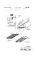
- FIG. 1 is a perspective view of a domestic refrigerator having an ice making compartment showing one embodiment of the invention in use;
- Fig. 2 is an enlarged perspective view of the ice making compartment shown in Fig. 1 with an ice-cube pan therein.
- Fig. 3 is a perspective view of a reticulated mat suitable for use in practicing my invention.
- Fig. 4 is a perspective view of a modified form of reticulated mat.
- a well known type of ice making compartment is shown as 5, and being 35 of the usual construction .need not be described in detail.
- This compartment contains a chamber 6 having the floor 7 upon which a usual ice making receptacle 8 has heretofore been placed in direct contact with said floor 7.
- frost During the ice making period considerable frost accumulates upon the surfaces of the ice making compartment, and heretofore the receptacle 8 when placed in direct contact with the frost accumulating surface has frozen fast thereto.
- a reticulated mat 9 is interposed between the bottom of the receptacle 8 and the floor 7. The retill) till ceptacle having an extended surface ceptacle 8 will then not freeze to the com partment and will not freeze to the mat 9.
- llhe mat 9 as shown in Fig. 2 is preferably formed with upstanding side members 10 and of a shape designed to fit over the floor of the chamber 6 and is preferably made of wire mesh of copper copper bronze or galvanized iron. As above noted, a mat having ll mesh to the inch is suitable but the mat may be of coarser or finer mesh.
- the mat 9 is made as a unit and may be used in the ice making compartments of refrigerators already in general use, being removable at will to allow for cleaning or for any other purpose.
- the upstanding edge members 10 extend between the walls of the receptacle e and the walls of the chamber 6 to prevent freezing to the side walls and also to facilitate removal of the mat.
- llhe' mat 9 does not interfere with the ice making in the recepta cle, nor does it freeze to the floor '21, but it rests upon the frost formed in the compartment.
- the receptacle may easily and readily be removed from the compartment 5 by simply lifting it from, or sliding it along. the mat 9.
- Fig. 3 there is shown a modified form of mat ll of the same mesh material as the mat 9..
- spaced apertures 12 extending lengthwise which increase the air space between the floor '3" of the compartment and the receptacle 8. lllpstand ing edges are shown at l3, l3 similar to edges l0. 10 of Fig. 2.
Landscapes
- Engineering & Computer Science (AREA)
- Physics & Mathematics (AREA)
- Mechanical Engineering (AREA)
- Thermal Sciences (AREA)
- General Engineering & Computer Science (AREA)
- Devices That Are Associated With Refrigeration Equipment (AREA)
Description
March 29, 1932. K. TOWNSEND 1,851,740
APPARATUS FOR PREVENTING ADHESION BY FROSTING Filed Aug. 8, 1930 llnwaKTozdnsenq Patented Mar. 29, 1932 UNITED STATES PATENT OFFICE LAURA K. TOWNSEND, OF PHILADELPHIA, PENNSYLVANIA 3 Application filed August 8, 1930. Serial No. 473,970.
My invention is an ,improved apparatus for preventing the frosting together of a refrigerating element and a refrigerated element having extended surfaces in close prox- 5 imity to one another; such frosting together occurring particularly when a metal recep- V tacle containing a liquid to be frozen is placed in close proximity to a metal surface cooled by a. low temperature refrigerant. Under such circumstancesa film or layer of frost or ice commonly forms between and firmly binds together the juxtaposed metal surfaces.
I have found, however, that if the surface of such film or layer of frost adjacent to the 16 receptacle is divided into minute sections, its adhesionto the receptacle is destroyed or minimized so that its holding power is negligible and the receptacle may be readily removed -from the refrigerating surface. I 20 have found that the'interposition of a mesh 1 fabric, such for instance as ordinary copper fly screening having say 14 meshes to the inch, eflectively prevents the frostin together of the liquid receptacle and refriger- 2 ating surface, such mesh fabric seemingly floating on the surface of and subdividing the frost layer and permitting the passage of some air betweenthe surfaces without materially decreasing the freezingefi'ect. The
mesh fabric does not become embedded in the frost layer to any material extent and seems to havesomewhat the action of a snow-shoe and both the mesh fabric and liquid receptacle may be readily withdrawn.
My invention, while of general application, is particularly applicable to domestic refrigerators of the electric or gas operated type," for preventing the frosting together of the ice-cube pan and the chilling'unit.
There is-in general use, at present, a type of refrigerator, in which the bottom of the ice making receptacle rests directly upon the bottom of the ice making compartment, with the result that during the eriod necessary to make ice, the receptacleis frozen fast to the bottom surface of the compartment by the film or layer of frost resulting from condensation and freezing of moisture between the juxtaposed surfaces of the receptacle and compartment. To dislodge the receptacle it has been necessary either to partially defrost the compartment or to use considerable force to free the receptacle, neither of which is desirable or convenient. "It is, therefore, an object of this invention to provide means designed to be placed between the ice making receptacle and the ice making compartment in this type of refrigerator to minimize the adhesion between the receptacle and the compartment, and to this end a reticulated mat is placed upon the floor of the ice making compartment and the ice making receptacle rests upon and is floated upon the frost layer by this mat and a slight air space is provided between the receptacle and the compartment surfaces.
Additional objects and advantages of the invention will be apparent from the following description and the accompanyin drawings of an illustrative embodiment o my invention, in which c Fig. 1 is a perspective view of a domestic refrigerator having an ice making compartment showing one embodiment of the invention in use;
Fig. 2 is an enlarged perspective view of the ice making compartment shown in Fig. 1 with an ice-cube pan therein.
Fig. 3 is a perspective view of a reticulated mat suitable for use in practicing my invention, and
Fig. 4 is a perspective view of a modified form of reticulated mat.
In the drawings, a well known type of ice making compartment is shown as 5, and being 35 of the usual construction .need not be described in detail. This compartment contains a chamber 6 having the floor 7 upon which a usual ice making receptacle 8 has heretofore been placed in direct contact with said floor 7. During the ice making period considerable frost accumulates upon the surfaces of the ice making compartment, and heretofore the receptacle 8 when placed in direct contact with the frost accumulating surface has frozen fast thereto.
In accordance with my invention, a reticulated mat 9 is interposed between the bottom of the receptacle 8 and the floor 7. The retill) till ceptacle having an extended surface ceptacle 8 will then not freeze to the com partment and will not freeze to the mat 9.
llhe mat 9 as shown in Fig. 2 is preferably formed with upstanding side members 10 and of a shape designed to fit over the floor of the chamber 6 and is preferably made of wire mesh of copper copper bronze or galvanized iron. As above noted, a mat having ll mesh to the inch is suitable but the mat may be of coarser or finer mesh. The mat 9 is made as a unit and may be used in the ice making compartments of refrigerators already in general use, being removable at will to allow for cleaning or for any other purpose. The upstanding edge members 10 extend between the walls of the receptacle e and the walls of the chamber 6 to prevent freezing to the side walls and also to facilitate removal of the mat. llhe' mat 9 does not interfere with the ice making in the recepta cle, nor does it freeze to the floor '21, but it rests upon the frost formed in the compartment. After ice has been formed in the receptacle 8, with the mat 9 in position of Fig. 1, the receptacle may easily and readily be removed from the compartment 5 by simply lifting it from, or sliding it along. the mat 9. ln Fig. 3, there is shown a modified form of mat ll of the same mesh material as the mat 9.. There is provided, however, spaced apertures 12 extending lengthwise which increase the air space between the floor '3" of the compartment and the receptacle 8. lllpstand ing edges are shown at l3, l3 similar to edges l0. 10 of Fig. 2.
Having described my invention, l claim: 1. llhe combination with an ice making compartment having an extended frost accumulating surface and an ice making rein close juxtaposition to the first named surface of a metallic wire mesh fabric interposed be-,
tween and in close said surfaces. j
2. The combination with an ice making compartment havingcan extended frost accumulatirrg surface and an ice making receptacle having an extended surface in close juxtaposition to the first named surface of a reticulated metallic mat interposed between and in close juxtaposition to both said sur-- faces.
3. The combination with an, ice making compartment having an extended frost acjuxtaposition to both cumulating surface and an ice making receptacle having an extended surface in close juxtaposition to the first named surface of a wire mesh'mat interposed between and in close juxtaposition to both said surfaces.
4. The, combination with an ice making compartment having an extended frost accumulating surface and an ice making receptacle having an extended surface in close uxtaposition to the first named surface of rename a wire screening interposed and providing an air space between said surfaces.
5. The combination with an compartment having an extended frost accum'ulating surface and an ice making receptacle having an extended surface in close juxtaposition to the first named surface of a removable wire screening mat interposed between and in close juxtaposition to both said surfaces.
6. lhe combination with an ice making compartment having an extended frost accumulating surface and an ice making receptacle having an extended surface in close juxtaposition to the first named surface of a removable reticulated wire mat interposed between and in close juxtaposition to both said surfaces.
i. The combination with an ice making compartment having an extended frost accumulating surface and an ice making re cept acle having an extended surface in close juxtaposition to the first named surface of a mat interposed mat being made of mesh fabric having striplilre apertures therein.
lln testimony .whereof l have hereunto set my hand this 6th day of Amugust 1930.
LMURA lit. TUllVllEildllL-t ice making between said surfares saidltlti llUti 'ili)
Priority Applications (1)
| Application Number | Priority Date | Filing Date | Title |
|---|---|---|---|
| US473970A US1851740A (en) | 1930-08-08 | 1930-08-08 | Apparatus for preventing adhesion by frosting |
Applications Claiming Priority (1)
| Application Number | Priority Date | Filing Date | Title |
|---|---|---|---|
| US473970A US1851740A (en) | 1930-08-08 | 1930-08-08 | Apparatus for preventing adhesion by frosting |
Publications (1)
| Publication Number | Publication Date |
|---|---|
| US1851740A true US1851740A (en) | 1932-03-29 |
Family
ID=23881722
Family Applications (1)
| Application Number | Title | Priority Date | Filing Date |
|---|---|---|---|
| US473970A Expired - Lifetime US1851740A (en) | 1930-08-08 | 1930-08-08 | Apparatus for preventing adhesion by frosting |
Country Status (1)
| Country | Link |
|---|---|
| US (1) | US1851740A (en) |
Cited By (3)
| Publication number | Priority date | Publication date | Assignee | Title |
|---|---|---|---|---|
| US2429521A (en) * | 1945-09-06 | 1947-10-21 | Harry G Marquis | Ice tray appliance |
| US2512759A (en) * | 1947-02-26 | 1950-06-27 | Model Crafters Inc | Device to facilitate the removal of ice trays |
| US3033004A (en) * | 1960-01-08 | 1962-05-08 | Controls Co Of America | Defrost control responsive to frost accumulation |
-
1930
- 1930-08-08 US US473970A patent/US1851740A/en not_active Expired - Lifetime
Cited By (3)
| Publication number | Priority date | Publication date | Assignee | Title |
|---|---|---|---|---|
| US2429521A (en) * | 1945-09-06 | 1947-10-21 | Harry G Marquis | Ice tray appliance |
| US2512759A (en) * | 1947-02-26 | 1950-06-27 | Model Crafters Inc | Device to facilitate the removal of ice trays |
| US3033004A (en) * | 1960-01-08 | 1962-05-08 | Controls Co Of America | Defrost control responsive to frost accumulation |
Similar Documents
| Publication | Publication Date | Title |
|---|---|---|
| US2846854A (en) | Ice cube maker | |
| US2765633A (en) | Defrosting of evaporator | |
| US2717505A (en) | Ice receptacle and drip tray | |
| US3224216A (en) | Refrigerator defrost tray | |
| US2592394A (en) | Refrigerator defrost product disposal system | |
| US2370267A (en) | Refrigerating apparatus | |
| US1851740A (en) | Apparatus for preventing adhesion by frosting | |
| US2478312A (en) | Refrigerator, including an evaporator and ice cube tray arrangement for cooling the food storage compartment | |
| US2721451A (en) | Drain pan | |
| US2510758A (en) | Refrigerator having a baffle structure | |
| US3050957A (en) | Defrost water drain seal | |
| US2181580A (en) | Ice tray | |
| US3081608A (en) | Frozen food compartment for domestic refrigerator | |
| US1873508A (en) | Refrigeration | |
| US2196244A (en) | Ice spoon | |
| US1827410A (en) | Defrosting refrigeration system | |
| US2890574A (en) | Frost attractor for refrigerators | |
| US1973033A (en) | Ice tray | |
| US1755084A (en) | Refrigerating machine | |
| US2595874A (en) | Insulation arrangement for combination refrigerators | |
| US2029860A (en) | Refrigerator display case | |
| US1963565A (en) | Refrigerator | |
| US2215192A (en) | Cooler apparatus | |
| US2686404A (en) | Ice-cream making plate | |
| US1836040A (en) | Refrigerating apparatus |