US1851736A - Pot head - Google Patents
Pot head Download PDFInfo
- Publication number
- US1851736A US1851736A US330956A US33095629A US1851736A US 1851736 A US1851736 A US 1851736A US 330956 A US330956 A US 330956A US 33095629 A US33095629 A US 33095629A US 1851736 A US1851736 A US 1851736A
- Authority
- US
- United States
- Prior art keywords
- cable
- bushing
- pot head
- tapered bore
- inlet
- Prior art date
- Legal status (The legal status is an assumption and is not a legal conclusion. Google has not performed a legal analysis and makes no representation as to the accuracy of the status listed.)
- Expired - Lifetime
Links
- 239000002184 metal Substances 0.000 description 7
- 238000012856 packing Methods 0.000 description 2
- 238000004873 anchoring Methods 0.000 description 1
- 239000004020 conductor Substances 0.000 description 1
- 238000010276 construction Methods 0.000 description 1
- 239000000463 material Substances 0.000 description 1
- 238000007789 sealing Methods 0.000 description 1
Images
Classifications
-
- H—ELECTRICITY
- H02—GENERATION; CONVERSION OR DISTRIBUTION OF ELECTRIC POWER
- H02G—INSTALLATION OF ELECTRIC CABLES OR LINES, OR OF COMBINED OPTICAL AND ELECTRIC CABLES OR LINES
- H02G15/00—Cable fittings
- H02G15/02—Cable terminations
- H02G15/06—Cable terminating boxes, frames or other structures
Definitions
- This invention relates to certain new and useful improvements in pot heads and contemplates as an object the provision of means for hermetically sealing the inlet of the pot head through which the cable enters.
- Another object of this invention resides in the provision of a stuliing box or packing for the inlet of a pot head, which is formed of metal to provide means for grounding the cable sheath to prevent electrostatic discharges.
- Figure 1 is a view, partly in elevation and partly in section, of a pot head embodying 0 my invention
- Figure 2 is a cross sectional view taken through Figure 1 on the plane of the line 22;
- Figure 3 is an enlarged, fragmentary detail view illustrating the packing or seal which surrounds the cable sheath at its point of entrance to the pot head, parts thereof being in section and parts in elevation.
- 5 represents the casing or body of a pot head of conventional design having an inlet 6 at its lower end and having a cover 5 7 closing its open top.
- a cable 8 extends through the inlet opening 6 and has its outer covering stripped to bare its several conductors 9 which are fanned outwardly through insultor bushings 10 secured in the cover, to be connected at their outer ends with terminal bore 18 is tapered to receive a correspondingly shaped bushing member 20.
- the bushing member 20 snugly engages the lead sheath 19 of the cable and is preferably formed of a substantially soft metal such as lead or the like.
- a plurality of longitudinal slots 21 extend downwardly from the top of the bushing member 20 and terminate a short distance from the bottom tiereof to substantially divide the bushing member into a plurality of segments which are adapted to be urged toward each other to securely clamp the lead sheath 19 of the cable upon being forced into the tapered bore 18 by a pressure applying member or ring 22.
- the ring 22 surrounds the upper reduced portion 23 of the bushing member 20 and has its lower periphery engaged with a shoulder 24 formed by the reduced diameter 23.
- a plurality of cap screws 25 or the like passed through aperatures in the ring member 22 and threaded in the sleeve 17 provide means for forcing the bushing member 20 into the tapered bore 18, to securely grip the sheath of the cable; but inasmuch as the longitudinal slots 21 do not extend throughout the entire length of the bushing member it will be evident that a hermetic seal is provided at the inlet of the casing 5.
- the upper end of the bore extending through the bushing member 20 is preferably rounded, as at 26, and the end of the lead sheath 19 is pressed thereover, as at 27, to thus assist in preventing longitudinal movement of the cable with respect to the bushing.
- ring member surrounding the upper ends 01'' the several segments, and means for drawing the ring member toward said first mentioned member to force the bushing into the taperedbore and its several segments toward each other to securely clamp the cable extended therethrough and hermetically seal the inlet of the pot head.
- a pot head-having an inlet through which a sheathed cable extends a member positioned at the inlet and having a tapered bore, a bushing member formed of relatively soft metal mounted in the taperedbore and surrounding'the cable, means for forcing the bushing member into the tapered bore to securely clamp and anchor the cable and hermetically seal'the inlet of the pot head, and means extended from the bushing member and forming a substantially yielclable seat for the cabl sheath which is peened thereover.
- a bushingmember of deformable metal mounted in the tapered bore and surrounding the cable, said bushing member having longitudinal slots extended from one end thereof and terminating short of its opposite end to divide the major portion of the bushing into a plurality of segments, and means for forcing the bushing drawing the ring member toward said first mentioned member to force the bushing member into the tapered bore, the several segments of the bushing securely gripping the cable and anchoring the same in the tapered bore and its unslotted portion being wedged between the walls of'the tapered bore and the 1cable to hermetically seal the inlet to the pot lead.
- a pot head having a tapered bore in one wall to provide. an inlet adapted to receive a cable, a bushing of deformable metal mounted in the tapered bore and surrounding the cable, said bushing having a plurality of longitudinal slots dividing it into segments, each slot terminating short of one endof the bushing whereby adjacent segments are connected, and means for torcing the bushing into the tapered bore so that segments thereof securely grip the cable and anchor the samei'n the pot headinletand the metal of the'bushmg 1s wedged between the walls of the tapered bore and the cable to hermetically seal the inlet to the cable. 7 in testimony. whereof I have hereuntoaffixed my signature. 7
- a bushing member 'of'deformable metal mounted in the tapered bore and surroundingthe cable, the wall of the'bushing member being substantially wedge shaped in cross section and the bushing member having a plurality of longitudinal slots extending inwardly from its end of greater diameter and terminating short of its opposite end to divide the major portion thereof into aplurality of segments, a ringrmember sur- 7 65 rounding the several segments,,and means for r "lib
Landscapes
- Cable Accessories (AREA)
Description
March 29, 1932. A. G. STEiNMAYER 1,851,736
POT HEAD Filed Jan. 7, 1929 Patented Mar. 29, 1932 barren STATES PATENT @FFWF.
ALWIN G. STEINMAYER, OF MILWAUKEE, WISCONSIN, ASSIGNOB, BY ASSIGN- MENTS, TO LINE MATERIAL COMPANY, A CORPORATION OF DELAVJARE POT HEAD Application filed January 7, 1929. Serial No. 330,956.
This invention relates to certain new and useful improvements in pot heads and contemplates as an object the provision of means for hermetically sealing the inlet of the pot head through which the cable enters.
Another object of this invention resides in the provision of a stuliing box or packing for the inlet of a pot head, which is formed of metal to provide means for grounding the cable sheath to prevent electrostatic discharges.
/Vith the above and other objects in view which will appear as the description proceeds, my invention resides in the novel construction, combination and arrangement of parts substantially as hereinafter described and more particularly defined by the appended claims, it being understood that such changes in the precise embodiment of the hereindis- 0 closed invention may be made as come within the scope of the claims. 7
In the accompanying drawings, I have illustrated one complete example of the physical embodiment of my invention construct- 5 ed according to the best mode I have so far devised for the practical application of the principles thereof, and in which:
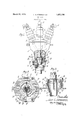
Figure 1 is a view, partly in elevation and partly in section, of a pot head embodying 0 my invention;
Figure 2 is a cross sectional view taken through Figure 1 on the plane of the line 22; and
Figure 3 is an enlarged, fragmentary detail view illustrating the packing or seal which surrounds the cable sheath at its point of entrance to the pot head, parts thereof being in section and parts in elevation.
Referring now more particularly to the accompanying drawing, in which like numerals designate like parts throughout the several views, 5 represents the casing or body of a pot head of conventional design having an inlet 6 at its lower end and having a cover 5 7 closing its open top. A cable 8 extends through the inlet opening 6 and has its outer covering stripped to bare its several conductors 9 which are fanned outwardly through insultor bushings 10 secured in the cover, to be connected at their outer ends with terminal bore 18 is tapered to receive a correspondingly shaped bushing member 20.
The bushing member 20 snugly engages the lead sheath 19 of the cable and is preferably formed of a substantially soft metal such as lead or the like. A plurality of longitudinal slots 21 extend downwardly from the top of the bushing member 20 and terminate a short distance from the bottom tiereof to substantially divide the bushing member into a plurality of segments which are adapted to be urged toward each other to securely clamp the lead sheath 19 of the cable upon being forced into the tapered bore 18 by a pressure applying member or ring 22.
The ring 22 surrounds the upper reduced portion 23 of the bushing member 20 and has its lower periphery engaged with a shoulder 24 formed by the reduced diameter 23. A plurality of cap screws 25 or the like passed through aperatures in the ring member 22 and threaded in the sleeve 17 provide means for forcing the bushing member 20 into the tapered bore 18, to securely grip the sheath of the cable; but inasmuch as the longitudinal slots 21 do not extend throughout the entire length of the bushing member it will be evident that a hermetic seal is provided at the inlet of the casing 5.
The upper end of the bore extending through the bushing member 20 is preferably rounded, as at 26, and the end of the lead sheath 19 is pressed thereover, as at 27, to thus assist in preventing longitudinal movement of the cable with respect to the bushing.
From the foregoing description, taken in connection with the accompanying drawing, it will be readily apparent to those skilled in Lil ' the artto which an invention of the character the tapered bore and having longitudinal slots substantially dividing it into segments, a
, ring member surrounding the upper ends 01'' the several segments, and means for drawing the ring member toward said first mentioned member to force the bushing into the taperedbore and its several segments toward each other to securely clamp the cable extended therethrough and hermetically seal the inlet of the pot head.
' 2' In a pot head-having an inlet through which a sheathed cable extends, a member positioned at the inlet and having a tapered bore, a bushing member formed of relatively soft metal mounted in the taperedbore and surrounding'the cable, means for forcing the bushing member into the tapered bore to securely clamp and anchor the cable and hermetically seal'the inlet of the pot head, and means extended from the bushing member and forming a substantially yielclable seat for the cabl sheath which is peened thereover. 3. In combination with a pot head having a tapered bore in onewall to provide an inlet adapted to receive a cable, a bushingmember of deformable metal mounted in the tapered bore and surrounding the cable, said bushing member having longitudinal slots extended from one end thereof and terminating short of its opposite end to divide the major portion of the bushing into a plurality of segments, and means for forcing the bushing drawing the ring member toward said first mentioned member to force the bushing member into the tapered bore, the several segments of the bushing securely gripping the cable and anchoring the same in the tapered bore and its unslotted portion being wedged between the walls of'the tapered bore and the 1cable to hermetically seal the inlet to the pot lead.
5. In combination withea pot head having a tapered bore in one wall to provide. an inlet adapted to receive a cable, a bushing of deformable metal mounted in the tapered bore and surrounding the cable, said bushing having a plurality of longitudinal slots dividing it into segments, each slot terminating short of one endof the bushing whereby adjacent segments are connected, and means for torcing the bushing into the tapered bore so that segments thereof securely grip the cable and anchor the samei'n the pot headinletand the metal of the'bushmg 1s wedged between the walls of the tapered bore and the cable to hermetically seal the inlet to the cable. 7 in testimony. whereof I have hereuntoaffixed my signature. 7
ALWIN o. STEINMAYER.
into the'tapered bore with its unslotted por- 7 tion innermost, the portion of the bushing divided into segments securely gripping the cable to anchor the same in thepothead inlet and the'unslotted portion of the bushing cooperating with'the walls of the cable and the tapered bore to hermetically seal the inlet to the pot head.
4. In combination with a pot head having 7 a'tapered bore in one wall to providean inlet adapted to receivea cable, a bushing member 'of'deformable metal mounted in the tapered bore and surroundingthe cable, the wall of the'bushing member being substantially wedge shaped in cross section and the bushing member having a plurality of longitudinal slots extending inwardly from its end of greater diameter and terminating short of its opposite end to divide the major portion thereof into aplurality of segments, a ringrmember sur- 7 65 rounding the several segments,,and means for r "lib
Priority Applications (1)
| Application Number | Priority Date | Filing Date | Title |
|---|---|---|---|
| US330956A US1851736A (en) | 1929-01-07 | 1929-01-07 | Pot head |
Applications Claiming Priority (1)
| Application Number | Priority Date | Filing Date | Title |
|---|---|---|---|
| US330956A US1851736A (en) | 1929-01-07 | 1929-01-07 | Pot head |
Publications (1)
| Publication Number | Publication Date |
|---|---|
| US1851736A true US1851736A (en) | 1932-03-29 |
Family
ID=23292020
Family Applications (1)
| Application Number | Title | Priority Date | Filing Date |
|---|---|---|---|
| US330956A Expired - Lifetime US1851736A (en) | 1929-01-07 | 1929-01-07 | Pot head |
Country Status (1)
| Country | Link |
|---|---|
| US (1) | US1851736A (en) |
-
1929
- 1929-01-07 US US330956A patent/US1851736A/en not_active Expired - Lifetime
Similar Documents
| Publication | Publication Date | Title |
|---|---|---|
| US2225472A (en) | Bushing | |
| US2938069A (en) | Compression type electrical connectors | |
| US2339488A (en) | Connector | |
| US2299037A (en) | Connector for electrical conductors or the like | |
| US3448223A (en) | Clamp for connecting electric wires | |
| US1851736A (en) | Pot head | |
| US2477172A (en) | Seismometer case cover | |
| US3175176A (en) | Electrical connection means in ignition coil unit or the like | |
| KR100872556B1 (en) | Connector for underground distribution line | |
| US1714590A (en) | Connecter | |
| US10141685B2 (en) | Power cable terminal | |
| KR100862369B1 (en) | Underground distributor | |
| US2560683A (en) | Wire splice connector | |
| KR102230588B1 (en) | Explosion proof type termination connection box | |
| US1793882A (en) | Cable connecter | |
| US1426210A (en) | Junction box for electric conductors | |
| US3439110A (en) | Prefabricated stress control shield | |
| US1882856A (en) | Strain relieving device for electrical conductor cords | |
| US1854782A (en) | Wire splicer | |
| US2057069A (en) | Oil-filled pot head | |
| US2794062A (en) | Sheathed electric cable | |
| US1873497A (en) | Pot head | |
| US2965700A (en) | Electrical wire splicing device | |
| US4070894A (en) | Crimping device | |
| US1878016A (en) | Pothead |