US1851734A - Coating machine - Google Patents
Coating machine Download PDFInfo
- Publication number
- US1851734A US1851734A US216502A US21650227A US1851734A US 1851734 A US1851734 A US 1851734A US 216502 A US216502 A US 216502A US 21650227 A US21650227 A US 21650227A US 1851734 A US1851734 A US 1851734A
- Authority
- US
- United States
- Prior art keywords
- conveyor
- tire
- shaft
- rigidly
- receptacle
- Prior art date
- Legal status (The legal status is an assumption and is not a legal conclusion. Google has not performed a legal analysis and makes no representation as to the accuracy of the status listed.)
- Expired - Lifetime
Links
- 239000011248 coating agent Substances 0.000 title description 10
- 238000000576 coating method Methods 0.000 title description 10
- 239000008199 coating composition Substances 0.000 description 10
- 239000007788 liquid Substances 0.000 description 5
- 239000003973 paint Substances 0.000 description 3
- 238000010422 painting Methods 0.000 description 3
- 230000005484 gravity Effects 0.000 description 2
- 239000000463 material Substances 0.000 description 2
- 239000000203 mixture Substances 0.000 description 2
- 230000001105 regulatory effect Effects 0.000 description 2
- 208000027418 Wounds and injury Diseases 0.000 description 1
- 238000010276 construction Methods 0.000 description 1
- 230000008602 contraction Effects 0.000 description 1
- 230000001276 controlling effect Effects 0.000 description 1
- 230000006378 damage Effects 0.000 description 1
- 238000001035 drying Methods 0.000 description 1
- 239000012530 fluid Substances 0.000 description 1
- 208000014674 injury Diseases 0.000 description 1
- 238000000034 method Methods 0.000 description 1
- 238000007665 sagging Methods 0.000 description 1
Images

Classifications
-
- B—PERFORMING OPERATIONS; TRANSPORTING
- B05—SPRAYING OR ATOMISING IN GENERAL; APPLYING FLUENT MATERIALS TO SURFACES, IN GENERAL
- B05C—APPARATUS FOR APPLYING FLUENT MATERIALS TO SURFACES, IN GENERAL
- B05C3/00—Apparatus in which the work is brought into contact with a bulk quantity of liquid or other fluent material
- B05C3/02—Apparatus in which the work is brought into contact with a bulk quantity of liquid or other fluent material the work being immersed in the liquid or other fluent material
Definitions
- This invention relates to a machine for coating articles with a fluid composition. More particularly it relates to a machine for painting truck tire flaps.
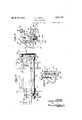
- Fig. 1 is a side elevation of the machine, partly broken away;
- Fig. 2 is a plan view of a portion of Fig. 1;
- Fig. 3 is a detail of a portion of a cross member of the conveyor illust-rating the mechanism for grippingthe flaps;
- Fig. 4 is a diagrammatic view illustrating the opening and closing of the gripping mechn anism
- Fig. 5 is a section along the line 5-5 of Fig. 3.
- the supporting frame of the machine is comprised Vof the beams 1 and 2 which are held in position by the angle bars 3 and 4 which extend between the same.
- a receptacle 5 for liquid coating composition is carried by the I-beams 6 and 7 which in turn are supported by the beams 1 and 2.
- An endless conveyor is provided for carrying the tire iiaps into and through the liquid coating composition in the receptacle 5.
- the continuous elements of this conveyor are the chains 8 and 9 which 5 are supported and driven at one end by the sprockets 10.
- These sprockets are mounted upon a shaft 11 which is ,carried rotatably by brackets 12 and 13 in a position directly over the receptacle 5.
- the brackets 12 andy 50.13 are rigidly aflixed to the beams 1 and 2 respectively,
- the tire liaps are secured against the members 17 by means of clamps or linger portions 19.
- the clamps 19 are mounted upon a shaft 20 which in turn is rotatably carried in brackets 21 which are secured by bolts 22 or otherwise to the cross bar 15.
- the shaft 20 extends the length of the cross bar 15 and the clamps 19 are positioned at the same intervals thereon as the knife edged supports 17 are positioned on the cross bars so that the knife edged supports 17 and the clamps 19 cooperate to grip the tire flaps.
- the clamp 19 grips the tire flaps with a flexible grip to compensate for slight variable thicknesses therein by the following arrangement of parts (see Figs. 3, 4 and 5).
- the clamp is pivotally mounted upon the shaft or supporting means 20.
- a bracket 59 is rigidly aiixed to the shaft by means of pins 60, the bracket being a U-shaped member and provided with an opening in which a bolt 61 can be rigidly secured, which bolt extends loosely through an opening in a flange 24 of the clamp 19.
- a spiral spring 62 is posi- ⁇ tioned around the bolt and bears atone end against the flange 24 and at the other end against the bracket 59.
- Each cross bar 15 is provided with a bracket 30 secured to the ends thereof by a bolt 31 which bolt passes through the brack- 10U et 21 securing the three elements as a unit.
- i wheel 63 which is rigidly aiixed upon a shaft
- the brackets 30 are provided with rolls 32 rotatably mounted on spindles 29 which latter project laterally from the bracket and are secured thereto by nuts 28.
- the rolls pro-v vide a bearing surface having a minimum of friction.
- rl ⁇ hey travel upon the guide rails 33 and 34which are positioned in an inclined path corresponding in general to the path of the conveyor.
- Rails 33 and 34 are rigidly secured to suitable-supports.35, 36 and 37 which in turn are rigidlyaili-Xed ⁇ to the beams 1 and 2.
- Suitable braces 38, 39 and 40 strengthen the supports 35, 36 and ⁇ :37.
- a bracket 47 projects rigidly from the ⁇ element 44 and carries an adjusting screw 48 by turningiwhich-the position of bearings 43 may he varied when bolts46 are loosened, to thereby tighten or loosen the chains 8 and 9.
- a nut 49 locks the screw48 in adjusted position.
- the bearing 43 carries rigidly a b-racket'50 which projects outwardly andV carries a roll 51 to unlatch the clamp 19 in a mannervto be described later.
- the conveyor is driven from a pulley 64.
- Shaft 64 is rotatably mounted in suitable bearings 65 and 66 which are rigidly' secured upon the beams 1 and 67 respectively.
- Shaft ⁇ 64 carries sprocket 68 rigidly secured thereto which is adapted to engage and drive a sprocket 69 which is rigidly secured to a shaft 70.
- the shaft 70 is rotatably mounted in bearings 71 and 72 which are rigidly secured to the beams 1 and 67 respectively.
- Shaft 70 carries rigidly a sprocket 73 which is adapted to mesh with a sprocket 74 rigidly secured upon the shaft 75.
- Shaft 75 is mounted Vfor rotation in bearings 76, 77 and 78 which are rigidly secured upon the beams 1, 67 and 2 respectively.
- a short crank 79 is rigidly aflixed'at one end to the shaft 75 and atits other end carries apintle 80 upon which a connecting rod 81 is rotatably mounted adjacentl one end thereof. At its opposite end thel rod l81 is securedby a pin 82'between the pawl arms 83 and 84 rotatively mounted on shaft 11.
- a ratchet wheel 85 is rigidly aiiixed to the shaft 11, between the pawl arms 83 and 84, and is provided with five shoul vders 86- positioned at equal intervals upon the periphery thereof.
- a pawl 87 is pivotally mounted in the pawl arms 83 and 84 on a pin 88, and is held in engagement with ratchet wheel 85 by a spring 89.
- the pawl 87 engages one of the shoulders 86 upon the ratchet wheel and forces the same in a counter-clockwise direction, as viewed in Fig. 1, for one-fifth of a revolution.
- the pawl 92 is normally maintained in engagement with the periphery ofthe ratchet wheel 85 by means of a spring 93 which is secured at one end to the .pawl190 ⁇ andat its opposite end to a bracket 94.
- the latter is supported by the brackets 12 and 13V and projectsA acrossthe conveyor in spaced relation thereto.
- Feedingv of the tire flaps to the conveyor is effected from the vtable 104 which ris rigidly secured to an angle bar 105 which latter is carried by and extends between the brackets 12 and 13.
- Brackets 106 project fromthe angle bar 105 at spaced intervals and carry spindle 107 upon which are rigidly mounted the guidesV 108 which latter are preferably positioned in pairs extending diagonally toward the conveyor and so placed that each pair is in alignment with a Clamp 19.
- the guides are adjustablefor any size tire flap by the following arrangement of elements.
- the spindle 107 carries at each end thereof rigidly secured thereto alever 109 to one end of which is attached a spring 110 which also is secured to .the bracket 94 and normally pulls ,this end of the lever 109 upwardly.
- the lever 109 is provided with a depending arm 111 through which there extends a set screw 112 which is designed to bear against a many sided cam 113 mounted upon a shaft 114 which in'turn is rotatably carried in the brackets 106.
- a knurled handiwheel 115 is rigidly secured at one end of the shaft 114 by turning which'the various surfaces of the cam 113 can be presented to the set screw 112, thereby regulating the distance which the Y guides 108 can be pulled upwardly angularly by the spring 11.0 and determining the positionof the guides 108.
- Tire flaps 116 are positioned upon the table 104. During each period of rest of the conveyor a cross bar 15 is positioned between guide 108 and bracket 94. One of the tire flaps is placed manually upon the knife edges of the cross bar 15 in such a position that one edge contacts with the guides 108. As the conveyor is moved forwardly in its intermittent travel, the tire ilapis held in position manually until the clamps 19 are sprung into position to grip it.
- the flap engages the guides 108 and depresses their outer ends about'the spindle 107 against the tension in the springllO until the tire flap -slides past the guides, when they are returned to their original position due to the contraction of the spring.
- the clamping action is elfected as follows (see Figs. 1, 3 and 4)
- the shaft 20 upon which the clamp 19 is carried is provided at its end with a tripping member 117 which is rigidly mounted thereon.
- Member 117 carries two projecting cam portions 118 and 119, the respective surfaces 120 and 121 of which are adapted to be engaged by suitable arms to rotate the member 117.
- a spring 122 is secured at one end to a projection 123 carried by the member 117 and at its other end is secured to a cross bar 15.
- An arm 124 is carried by each of the brackets 12 and 13 and is provided with a roll 125 which is so positioned that as the clamp 19 is carried past the same, the surface 120 of they projection 118 will be engaged by the roll and thereby rotate the tripping member 117, and as the member 117 rotates, the spring 122 connected thereto is carried across dead ccnter in position to yieldingly hold the clamp 19 against the iap.
- the tire flap held in position in the manner described, is conducted in intermittent travel through the paint receptacle 5 and outwardly to a position over a receptacle 126 at which position the clamps 19 are caused to release their grip upon the tire iiap and the latter is dropped by gravity into the receptacle 126.
- the unlatching of the clamp is effected by means of the roll 51 of the arm 50 which is carried by the bearing 43. This roll is engaged by the surface V121 of the projection 119 of the member 117 and turns the member 117 in its reverse rotary movement.
- Clamp 19 is ythus sprung outwardly to the position shown in dotted lines in Fig. 4 and is held in this position by the spring 122.
- the receptacle 126 into which the tire flaps drop may be of any construction desired, that illustrated in the drawings comprising a body portion 126 which is mounted upon wheels 127.
- any other suitable means for removing the tire iaps may be substituted, such for example as an endless conveyor.
- Coating material is supplied to the receptacle 5 from a reservoir 132 which is mounted at one side of the conveyor, being rigidly supported by two angle bars 133 and 134 which are carried by the base member 2.
- the reservoir 132 is connected to the paint receptacle 5 by means of a pipe 135, valve 136 controlling the supply of coating composition from reservoir 132 to receptacle 5.
- a stirrer is provided for agitating the coating composition in the reservoir 132, which stirrer is comprised of the beater arms 137 which are mounted on a horizontal shaft 138, which shaft is mounted rotatably in suitable bearings both in the reservoir132 and. in a bracket 139 which is secured to the support 35.
- Shaft 138 carries rigidly secured thereto a sprocket 140 about which a chain 141 passes.
- the opposite end of the cha-in is engaged and driven by a sprocket 142 .which is rigidly affixed to the shaft 7 5 previously described.
- a sprocket 143 is carried by a bracket 144 which depends from the lower side of the angle bar 133 and Vserves as a means for tightening the chain.
- the reservoir 132 is provided with a cover 144.
- a drip pan 145 extends diagonally upwardly from the rear end of the receptacle 5 to catch the drip from the tire fiaps as they are withdrawn from the body of coating composition.
- An overflow pipe 146 and a drain cock 147 yare attached to the paint receptacle 5.
- the con- Veyor is started in its intermittent travel and during a period of rest of the conveyor a tire iap 116 is taken, from a group of the same upon the table 104 and is positioned upon the supports 17 of a cross bar 15 which lies between guides 108 and 94.
- the tire Hap isk held in position upon the supports manually until the clamps 19 are caused to be sprung into clamping engagement with the tire flap.
- the tire flap is then conducted at a sharp angle into the receptacle containing coating composition, is carried therefrom at a sharp angle due to the inclination of the guide ⁇ rails 34 and is then conducted away by the conveyor, the latter being of suiiicient length to Vpermit the iap to dry.
- the dried tire Hap finally reaches a point in its tra-vel immediately over the receptacle 126, at which. point the grip of the cla-mp :upon the fiap isl released and the latter drops 'by gravity into receptacle 126 in which it may be removed to any desired location. yThe clamps continue their travel back to the position between the guide 108 and bracket 94 where another tire flap is positioned upon them.
- an article holder comprising, in combination, means for supporting the article, means for clamping the article to the supporting means, cam means whereby the clamping means may be manipulated to clamp and to release the article, and means comprising a single spring for maintaining the clamping means in clamping position and in releasing position.
- an article holder comprising, in combination, means for supporting the article, means for clamping the article to the supporting means, cam means whereby the clamping means may be manipulated to clamp and to release the article, means comprising a single spring forv maintaining the clamping means in clamping position and in releasing position,and spring means acting on the clamping means forrresiliently holding the article in place.
- a conveyor means for actuating the same, article supports carried by the conveyor, movable guide means mountedadjacent the conveyor for regulating the position of an article placed upon th-e supports, means for securing the article to the supports upon movement of the conveyor, said guide means extending into the path of travel of the article and being adapted to be brushed aside by engagement of the article therewith during travel of the conveyor, means associated with the guide means for returning the guide means to its original position, and a container for coating composition through which the article is adapted to be drawn by the conveyor.
- a coating apparatus comprising an endless conveyor, means for supporting and clamping a tire flap thereon, means for supplying a tire flap to said conveyor comprising pivotally mounted guides for supporting a tire lla-p before being placed in ⁇ clamped engagement With said conveyor and adapted to yieldingly move out of the path of said flap during its movement With the conveyor immediately following the clamping of the'flap to the conveyor.
- a coating apparatus comprising an endless conveyor, means for supporting and clamping a tire flap thereon, means for supplying a tire flap to said conveyor comprising pivotally mounted guides for supporting a tire flap before being placed in clamped Vengagement With said conveyor and adapted to yieldingly move out of the path of said Hap during its movement With the conveyor immediately following the clamping of the fiap to the conveyor, and means for returning said guides to their initial position preparatory to another clamping operation.
Landscapes
- Coating Apparatus (AREA)
Description
March 29, 1932. c. J. SMITH comme MACHINE:
Filed Aug. 51, 1927 2 seetswsheex 1 2 sheets-snet 2 C. J. SMITH COATING MACHINE Filed Aug. 3l.
INVENToR wydffma March 29, 1932.
Patented Mar. 29, 1932 UNITED STATES PATENT OFFICE CLYDE J'. SMITH, OF DETROIT,y MICHIGAN,ZASSIGNOR T0 MORGAN & WRIGHT, OF DETROIT, MICHIGAN, A. CORPORATION OF MICHIGAN COATING MACHINE Application led August 31, 1927. Serial No. 216,502.
This invention relates to a machine for coating articles with a fluid composition. More particularly it relates to a machine for painting truck tire flaps.
It has been customary in painting truck tire iiaps to dip the same manually into a body of liquid coating composition, after which they are suspended from a support until dry. Such a method has been time consuming,y has required considerable manual labor, and has resulted in defectively coated articles, unless a high degree of care and attention has been exerted by the operatives.l
It is an obj ect of this invention to provide a mechanism for automatically coating tire iaps with liquid coating composition and for drying the same without injury to the deposit of rcoating composition thereon. vOther objects will be apparent from the specification and from the drawings, in which latter:
Fig. 1 is a side elevation of the machine, partly broken away;
Fig. 2 is a plan view of a portion of Fig. 1;
Fig. 3 is a detail of a portion of a cross member of the conveyor illust-rating the mechanism for grippingthe flaps;
Fig. 4 is a diagrammatic view illustrating the opening and closing of the gripping mechn anism; and
Fig. 5 is a section along the line 5-5 of Fig. 3.
Referring particularly to the drawings, the supporting frame of the machine is comprised Vof the beams 1 and 2 which are held in position by the angle bars 3 and 4 which extend between the same. A receptacle 5 for liquid coating composition is carried by the I-beams 6 and 7 which in turn are supported by the beams 1 and 2. An endless conveyor is provided for carrying the tire iiaps into and through the liquid coating composition in the receptacle 5. The continuous elements of this conveyor are the chains 8 and 9 which 5 are supported and driven at one end by the sprockets 10. These sprockets are mounted upon a shaft 11 which is ,carried rotatably by brackets 12 and 13 in a position directly over the receptacle 5. The brackets 12 andy 50.13 are rigidly aflixed to the beams 1 and 2 respectively,
presents an almost continuous surface to the f liquid coating composition. The tire liaps are secured against the members 17 by means of clamps or linger portions 19. The clamps 19 are mounted upon a shaft 20 which in turn is rotatably carried in brackets 21 which are secured by bolts 22 or otherwise to the cross bar 15. The shaft 20 extends the length of the cross bar 15 and the clamps 19 are positioned at the same intervals thereon as the knife edged supports 17 are positioned on the cross bars so that the knife edged supports 17 and the clamps 19 cooperate to grip the tire flaps.
The clamp 19 grips the tire flaps with a flexible grip to compensate for slight variable thicknesses therein by the following arrangement of parts (see Figs. 3, 4 and 5). The clamp is pivotally mounted upon the shaft or supporting means 20. A bracket 59 is rigidly aiixed to the shaft by means of pins 60, the bracket being a U-shaped member and provided with an opening in which a bolt 61 can be rigidly secured, which bolt extends loosely through an opening in a flange 24 of the clamp 19. A spiral spring 62 is posi- `tioned around the bolt and bears atone end against the flange 24 and at the other end against the bracket 59. As the shaft 20 is rotated in a direction to cause the clamp 19 to grip the tire flap, the spring 62 will form a yielding abutment for the clamp. An angle bar 23 is secured to the under side of the brackets 21 serving as a brace or support for the cross bar 15.
Means are provided for guiding and for preventing sagging of the conveyor as follows: Each cross bar 15 is provided with a bracket 30 secured to the ends thereof by a bolt 31 which bolt passes through the brack- 10U et 21 securing the three elements as a unit.
i wheel 63 which is rigidly aiixed upon a shaft The brackets 30 are provided with rolls 32 rotatably mounted on spindles 29 which latter project laterally from the bracket and are secured thereto by nuts 28. The rolls pro-v vide a bearing surface having a minimum of friction. rl`hey travel upon the guide rails 33 and 34which are positioned in an inclined path corresponding in general to the path of the conveyor. Rails 33 and 34 are rigidly secured to suitable-supports.35, 36 and 37 which in turn are rigidlyaili-Xed `to the beams 1 and 2. Suitable braces 38, 39 and 40 strengthen the supports 35, 36 and `:37. ,It will be noted that the portions of rails 34 adjacent receptacle 5 are sharplyinclined At the discharge end of the conveyor the chains pass over sprockets 41 which are rotatably carried by the shaft 42. Shaft `42. is carried lin bearings 43 which are adjustably supported on elements 44 rigidly se` cured tothe rails 33-and134- The bearings .43 are provided with a plurality of slots 45 through which `there extend bolts 46 which adjus-tably secure the bearings `to the elements .44. A bracket 47 projects rigidly from the `element 44 and carries an adjusting screw 48 by turningiwhich-the position of bearings 43 may he varied when bolts46 are loosened, to thereby tighten or loosen the chains 8 and 9. A nut 49 locks the screw48 in adjusted position. The bearing 43 carries rigidly a b-racket'50 which projects outwardly andV carries a roll 51 to unlatch the clamp 19 in a mannervto be described later.
The conveyor is driven from a pulley 64. Shaft 64 is rotatably mounted in suitable bearings 65 and 66 which are rigidly' secured upon the beams 1 and 67 respectively. Shaft`64 carries sprocket 68 rigidly secured thereto which is adapted to engage and drive a sprocket 69 which is rigidly secured to a shaft 70. The shaft 70 is rotatably mounted in bearings 71 and 72 which are rigidly secured to the beams 1 and 67 respectively. Shaft 70 carries rigidly a sprocket 73 which is adapted to mesh with a sprocket 74 rigidly secured upon the shaft 75. Shaft 75 is mounted Vfor rotation in bearings 76, 77 and 78 which are rigidly secured upon the beams 1, 67 and 2 respectively. A short crank 79 is rigidly aflixed'at one end to the shaft 75 and atits other end carries apintle 80 upon which a connecting rod 81 is rotatably mounted adjacentl one end thereof. At its opposite end thel rod l81 is securedby a pin 82'between the pawl arms 83 and 84 rotatively mounted on shaft 11. A ratchet wheel 85 is rigidly aiiixed to the shaft 11, between the pawl arms 83 and 84, and is provided with five shoul vders 86- positioned at equal intervals upon the periphery thereof. A pawl 87 is pivotally mounted in the pawl arms 83 and 84 on a pin 88, and is held in engagement with ratchet wheel 85 by a spring 89. During movement of the rod 81 in one direction, the pawl 87 engages one of the shoulders 86 upon the ratchet wheel and forces the same in a counter-clockwise direction, as viewed in Fig. 1, for one-fifth of a revolution. Vhen the rod 81 moves rearwardly to engage a new shoulder 86, the ratchet wheel is prevented from possible clockwise rotation by means of a' pa'wl 92 which is pivotally mounted upon a bracket 91 which'projects voutwardly from the bracket 12. The pawl 92 is normally maintained in engagement with the periphery ofthe ratchet wheel 85 by means of a spring 93 which is secured at one end to the .pawl190` andat its opposite end to a bracket 94. The latter is supported by the brackets 12 and 13V and projectsA acrossthe conveyor in spaced relation thereto.
Feedingv of the tire flaps to the conveyor is effected from the vtable 104 which ris rigidly secured to an angle bar 105 which latter is carried by and extends between the brackets 12 and 13. Brackets 106 project fromthe angle bar 105 at spaced intervals and carry spindle 107 upon which are rigidly mounted the guidesV 108 which latter are preferably positioned in pairs extending diagonally toward the conveyor and so placed that each pair is in alignment with a Clamp 19. The guides are adjustablefor any size tire flap by the following arrangement of elements. The spindle 107 carries at each end thereof rigidly secured thereto alever 109 to one end of which is attached a spring 110 which also is secured to .the bracket 94 and normally pulls ,this end of the lever 109 upwardly. The lever 109 is provided with a depending arm 111 through which there extends a set screw 112 which is designed to bear against a many sided cam 113 mounted upon a shaft 114 which in'turn is rotatably carried in the brackets 106. A knurled handiwheel 115 is rigidly secured at one end of the shaft 114 by turning which'the various surfaces of the cam 113 can be presented to the set screw 112, thereby regulating the distance which the Y guides 108 can be pulled upwardly angularly by the spring 11.0 and determining the positionof the guides 108. Tire flaps 116 are positioned upon the table 104. During each period of rest of the conveyor a cross bar 15 is positioned between guide 108 and bracket 94. One of the tire flaps is placed manually upon the knife edges of the cross bar 15 in such a position that one edge contacts with the guides 108. As the conveyor is moved forwardly in its intermittent travel, the tire ilapis held in position manually until the clamps 19 are sprung into position to grip it. As the tire flap moves downwardly aroundthe sprockets 10, the flap engages the guides 108 and depresses their outer ends about'the spindle 107 against the tension in the springllO until the tire flap -slides past the guides, when they are returned to their original position due to the contraction of the spring. The clamping action is elfected as follows (see Figs. 1, 3 and 4) The shaft 20 upon which the clamp 19 is carried is provided at its end with a tripping member 117 which is rigidly mounted thereon. Member 117 carries two projecting cam portions 118 and 119, the respective surfaces 120 and 121 of which are adapted to be engaged by suitable arms to rotate the member 117. A spring 122 is secured at one end to a projection 123 carried by the member 117 and at its other end is secured to a cross bar 15. An arm 124 is carried by each of the brackets 12 and 13 and is provided with a roll 125 which is so positioned that as the clamp 19 is carried past the same, the surface 120 of they projection 118 will be engaged by the roll and thereby rotate the tripping member 117, and as the member 117 rotates, the spring 122 connected thereto is carried across dead ccnter in position to yieldingly hold the clamp 19 against the iap. The tire flap, held in position in the manner described, is conducted in intermittent travel through the paint receptacle 5 and outwardly to a position over a receptacle 126 at which position the clamps 19 are caused to release their grip upon the tire iiap and the latter is dropped by gravity into the receptacle 126. The unlatching of the clamp is effected by means of the roll 51 of the arm 50 which is carried by the bearing 43. This roll is engaged by the surface V121 of the projection 119 of the member 117 and turns the member 117 in its reverse rotary movement. Clamp 19 is ythus sprung outwardly to the position shown in dotted lines in Fig. 4 and is held in this position by the spring 122. The receptacle 126 into which the tire flaps drop may be of any construction desired, that illustrated in the drawings comprising a body portion 126 which is mounted upon wheels 127. In place of the receptacle 126 any other suitable means for removing the tire iaps may be substituted, such for example as an endless conveyor.
Coating material is supplied to the receptacle 5 from a reservoir 132 which is mounted at one side of the conveyor, being rigidly supported by two angle bars 133 and 134 which are carried by the base member 2. The reservoir 132 is connected to the paint receptacle 5 by means of a pipe 135, valve 136 controlling the supply of coating composition from reservoir 132 to receptacle 5. A stirrer is provided for agitating the coating composition in the reservoir 132, which stirrer is comprised of the beater arms 137 which are mounted on a horizontal shaft 138, which shaft is mounted rotatably in suitable bearings both in the reservoir132 and. in a bracket 139 which is secured to the support 35. Shaft 138 carries rigidly secured thereto a sprocket 140 about which a chain 141 passes. The opposite end of the cha-in is engaged and driven by a sprocket 142 .which is rigidly affixed to the shaft 7 5 previously described. A sprocket 143 is carried by a bracket 144 which depends from the lower side of the angle bar 133 and Vserves as a means for tightening the chain. The reservoir 132 is provided with a cover 144. A drip pan 145 extends diagonally upwardly from the rear end of the receptacle 5 to catch the drip from the tire fiaps as they are withdrawn from the body of coating composition. An overflow pipe 146 and a drain cock 147 yare attached to the paint receptacle 5.
yIn the operation of the machine, the con- Veyor is started in its intermittent travel and during a period of rest of the conveyor a tire iap 116 is taken, from a group of the same upon the table 104 and is positioned upon the supports 17 of a cross bar 15 which lies between guides 108 and 94. As the conveyor continues its intermittent travel, the tire Hap isk held in position upon the supports manually until the clamps 19 are caused to be sprung into clamping engagement with the tire flap. The tire flap is then conducted at a sharp angle into the receptacle containing coating composition, is carried therefrom at a sharp angle due to the inclination of the guide` rails 34 and is then conducted away by the conveyor, the latter being of suiiicient length to Vpermit the iap to dry. The dried tire Hap finally reaches a point in its tra-vel immediately over the receptacle 126, at which. point the grip of the cla-mp :upon the fiap isl released and the latter drops 'by gravity into receptacle 126 in which it may be removed to any desired location. yThe clamps continue their travel back to the position between the guide 108 and bracket 94 where another tire flap is positioned upon them.
While the invention has been particularly described asy applied to the painting of truck tire flaps with coating material, it will be understood that any other elongated object which can be carried by the machine will be coated equally as well and the claims are to be so understood. e f
Having thus described my invention, what I claim and desire to protect by Letters Patent is:
1. In a conveyor, an article holder comprising, in combination, means for supporting the article, means for clamping the article to the supporting means, cam means whereby the clamping means may be manipulated to clamp and to release the article, and means comprising a single spring for maintaining the clamping means in clamping position and in releasing position.
2. In a conveyor, an article holder comprising, in combination, means for supporting the article, means for clamping the article to the supporting means, cam means whereby the clamping means may be manipulated to clamp and to release the article, means comprising a single spring forv maintaining the clamping means in clamping position and in releasing position,and spring means acting on the clamping means forrresiliently holding the article in place.
3. In a coating apparatus, a conveyor, means for actuating the same, article supports carried by the conveyor, movable guide means mountedadjacent the conveyor for regulating the position of an article placed upon th-e supports, means for securing the article to the supports upon movement of the conveyor, said guide means extending into the path of travel of the article and being adapted to be brushed aside by engagement of the article therewith during travel of the conveyor, means associated with the guide means for returning the guide means to its original position, and a container for coating composition through which the article is adapted to be drawn by the conveyor.
4. A coating apparatus comprising an endless conveyor, means for supporting and clamping a tire flap thereon, means for supplying a tire flap to said conveyor comprising pivotally mounted guides for supporting a tire lla-p before being placed in `clamped engagement With said conveyor and adapted to yieldingly move out of the path of said flap during its movement With the conveyor immediately following the clamping of the'flap to the conveyor.
5. A coating apparatus comprising an endless conveyor, means for supporting and clamping a tire flap thereon, means for supplying a tire flap to said conveyor comprising pivotally mounted guides for supporting a tire flap before being placed in clamped Vengagement With said conveyor and adapted to yieldingly move out of the path of said Hap during its movement With the conveyor immediately following the clamping of the fiap to the conveyor, and means for returning said guides to their initial position preparatory to another clamping operation.
Signed at Detroit, county of Wayne, State of Michigan, this 26th day of August, 1927.
CLYDE J. SMITH.`
Priority Applications (1)
| Application Number | Priority Date | Filing Date | Title |
|---|---|---|---|
| US216502A US1851734A (en) | 1927-08-31 | 1927-08-31 | Coating machine |
Applications Claiming Priority (1)
| Application Number | Priority Date | Filing Date | Title |
|---|---|---|---|
| US216502A US1851734A (en) | 1927-08-31 | 1927-08-31 | Coating machine |
Publications (1)
| Publication Number | Publication Date |
|---|---|
| US1851734A true US1851734A (en) | 1932-03-29 |
Family
ID=22807301
Family Applications (1)
| Application Number | Title | Priority Date | Filing Date |
|---|---|---|---|
| US216502A Expired - Lifetime US1851734A (en) | 1927-08-31 | 1927-08-31 | Coating machine |
Country Status (1)
| Country | Link |
|---|---|
| US (1) | US1851734A (en) |
Cited By (1)
| Publication number | Priority date | Publication date | Assignee | Title |
|---|---|---|---|---|
| US3063409A (en) * | 1959-02-06 | 1962-11-13 | Blaw Knox Co | Apparatus for continuous coating of elongated articles |
-
1927
- 1927-08-31 US US216502A patent/US1851734A/en not_active Expired - Lifetime
Cited By (1)
| Publication number | Priority date | Publication date | Assignee | Title |
|---|---|---|---|---|
| US3063409A (en) * | 1959-02-06 | 1962-11-13 | Blaw Knox Co | Apparatus for continuous coating of elongated articles |
Similar Documents
| Publication | Publication Date | Title |
|---|---|---|
| CA2674863A1 (en) | Device for forming sleeve-like foil envelopes from a continuous flat strip of foil material | |
| EP0569335B1 (en) | Device for filling of flexible bags | |
| US1851734A (en) | Coating machine | |
| US2640584A (en) | Automatic coating and draining machine | |
| US2367168A (en) | Package binding | |
| US3756894A (en) | Reel capping apparatus | |
| US2745374A (en) | Machine for coating apples on sticks | |
| US1056291A (en) | Apparatus for coating articles. | |
| US1953300A (en) | Apparatus for handling shingles | |
| US1042914A (en) | Machine for coating articles with paraffin or other coating material. | |
| DE1586380C3 (en) | Device for applying a self-adhesive adhesive film to removed labels from a storage container | |
| US729512A (en) | Apparatus for painting cans. | |
| US533443A (en) | dejong-e | |
| US1956344A (en) | Soldering machine | |
| US2838025A (en) | Article conveying apparatus for use with spray paint guns | |
| US3077821A (en) | Latex gumming attachment for envelope folding machines | |
| US1494436A (en) | Clamp for use in coating battery boxes and the like | |
| US1137243A (en) | Machine for applying reinforcing means to rug-seams. | |
| DE697792C (en) | Device for wrapping workpieces such as boxes etc. | |
| US1310355A (en) | Wall-paper-pasting machine | |
| US3497412A (en) | Label applying apparatus | |
| US1344426A (en) | Labeling-machine | |
| US1974859A (en) | Felt stretching machine | |
| US1646359A (en) | Island | |
| DE1014922B (en) | Device for simultaneous labeling and foil wrapping of bottles |