US1851728A - Artistic box - Google Patents
Artistic box Download PDFInfo
- Publication number
- US1851728A US1851728A US375652A US37565229A US1851728A US 1851728 A US1851728 A US 1851728A US 375652 A US375652 A US 375652A US 37565229 A US37565229 A US 37565229A US 1851728 A US1851728 A US 1851728A
- Authority
- US
- United States
- Prior art keywords
- lid
- box
- edges
- parts
- edge
- Prior art date
- Legal status (The legal status is an assumption and is not a legal conclusion. Google has not performed a legal analysis and makes no representation as to the accuracy of the status listed.)
- Expired - Lifetime
Links
- 238000010276 construction Methods 0.000 description 6
- 230000000694 effects Effects 0.000 description 6
- 239000000463 material Substances 0.000 description 6
- 239000004744 fabric Substances 0.000 description 3
- 238000004519 manufacturing process Methods 0.000 description 3
- 230000003014 reinforcing effect Effects 0.000 description 3
- 238000004026 adhesive bonding Methods 0.000 description 2
- 239000007787 solid Substances 0.000 description 2
- 241001139376 Allas Species 0.000 description 1
- 239000000843 powder Substances 0.000 description 1
- PHWXUGHIIBDVKD-UHFFFAOYSA-N sitaxentan Chemical compound CC1=NOC(NS(=O)(=O)C2=C(SC=C2)C(=O)CC=2C(=CC=3OCOC=3C=2)C)=C1Cl PHWXUGHIIBDVKD-UHFFFAOYSA-N 0.000 description 1
- 229960002578 sitaxentan Drugs 0.000 description 1
Images
Classifications
-
- B—PERFORMING OPERATIONS; TRANSPORTING
- B65—CONVEYING; PACKING; STORING; HANDLING THIN OR FILAMENTARY MATERIAL
- B65D—CONTAINERS FOR STORAGE OR TRANSPORT OF ARTICLES OR MATERIALS, e.g. BAGS, BARRELS, BOTTLES, BOXES, CANS, CARTONS, CRATES, DRUMS, JARS, TANKS, HOPPERS, FORWARDING CONTAINERS; ACCESSORIES, CLOSURES, OR FITTINGS THEREFOR; PACKAGING ELEMENTS; PACKAGES
- B65D5/00—Rigid or semi-rigid containers of polygonal cross-section, e.g. boxes, cartons or trays, formed by folding or erecting one or more blanks made of paper
- B65D5/42—Details of containers or of foldable or erectable container blanks
- B65D5/64—Lids
-
- Y—GENERAL TAGGING OF NEW TECHNOLOGICAL DEVELOPMENTS; GENERAL TAGGING OF CROSS-SECTIONAL TECHNOLOGIES SPANNING OVER SEVERAL SECTIONS OF THE IPC; TECHNICAL SUBJECTS COVERED BY FORMER USPC CROSS-REFERENCE ART COLLECTIONS [XRACs] AND DIGESTS
- Y10—TECHNICAL SUBJECTS COVERED BY FORMER USPC
- Y10S—TECHNICAL SUBJECTS COVERED BY FORMER USPC CROSS-REFERENCE ART COLLECTIONS [XRACs] AND DIGESTS
- Y10S229/00—Envelopes, wrappers, and paperboard boxes
- Y10S229/915—Stacking feature
-
- Y—GENERAL TAGGING OF NEW TECHNOLOGICAL DEVELOPMENTS; GENERAL TAGGING OF CROSS-SECTIONAL TECHNOLOGIES SPANNING OVER SEVERAL SECTIONS OF THE IPC; TECHNICAL SUBJECTS COVERED BY FORMER USPC CROSS-REFERENCE ART COLLECTIONS [XRACs] AND DIGESTS
- Y10—TECHNICAL SUBJECTS COVERED BY FORMER USPC
- Y10S—TECHNICAL SUBJECTS COVERED BY FORMER USPC CROSS-REFERENCE ART COLLECTIONS [XRACs] AND DIGESTS
- Y10S229/00—Envelopes, wrappers, and paperboard boxes
- Y10S229/922—Envelopes, wrappers, and paperboard boxes with decorative feature
Definitions
- This invention relates to decorative receptacles or containers and more particularly to improvements in the structure thereof whereby to enhance and improve the-external;
- a still further object of the-invention isto generally improve and enhance the appear ance of the multiple-part lid by so constructmg and relatively arrangingthe severallidparts that the proximate edges thereof abut one another to form a neat. andinconspicuous joint-when the same are in closedposition;
- Still another object of the present invention is to provide a lid'of sectional construction comprising-avplurality of superimposed panels the exposedsurfaces of'which' are enveloped or covered in such manner as to conceal the edges thereofwhereby to give the im pression' and effect of a solidlid structure.
- a fur ther object of the invention is to provide a hinged connection between each ofthe lidparts and the respective upper edgesof the receptacle which is not only strong and durable in construction, but alsooffsuch character a he hinge e nt ndr dv' ae t a y invisible when the lid is either inclosed or open position.
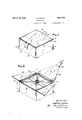
- Figure 1' is a perspective view of a recep tacleconstructed in accordance with the present invention, the lid. being. shown” in. com pletely closediposition;
- Figure2 is a perspective viewshowing the lidpartsin fully openposition
- Figure 3 is a similar view showingthe lid parts inpartly openedposition
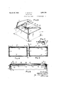
- Figure 4 is a vertical sectional view taken onthe line extending through the mid points of the opposite sideedges of-the box shown in Figurel; i
- Figure '5' i sa vertical sectional viewtaken onv the line extending through the midpoints'. of the front and rear edges oftheb ox'shown in Figure'l l
- Figure 6 is an enlarged sectional view of the lid construction as shown in Figured; and- F igure? ,is an enlarged view ofthesec tion' enclosed. within the broken circle of Figure 5.
- the outer shell of the box proper is constructed inthe conventional manner and is designated generally by the reference numeral 11 Suitably/secured to thelin'ner surfaces of the front, rear and side walls of this shell 11, preferably by gluing or pasting, or the inner reinforcing panels 12, the arrangement being such that the shell is provided with walls of double thickness.
- Removably disposed within the shell so formed is an interior open topped box 13 having a botto1n14 and front, rear and side walls respectively overlying said panels 12.
- the upper edges of the interior box lie in a plane somewhat below that of the upper edges of the shell 11 whereby to provide a continuously extending ledge 15 for supporting the perimetral edges of a lid therefor.
- each of the side parts 17-17 of the lid is provided with a straight outer edge 18, an obliquely extending inner edge 19, a frontal edge 20 and a rear edge 21, said frontal and rear edges being extended at right angles to the outer edge 18 and the frontal edge being of greater width than the rear edge.
- a hinge element 22 interconnecting the outer edge of each lid part 17 with the upper edge of the corresponding side wall of the box 11 is a hinge element 22, preferably in the form of a flexible strip of cloth or other such material.
- the connection between the adjoining edges of the lid parts 1717 and the box will be described more fully hereinafter, it being sufficient to point out at this time that the hinged connection is such that the edges 18, 20 and 21 of the lid rest upon the ledge 15 which is formed by the interior box 13.
- the intermediate'lid part 2% is generally of triangular form'having the obliquely extending side edges 25 and the straight front and rear edges 26 and 27, respectively.
- the obliquely extending side edges 25 of this intermediate lid part 24 are contiguous to the inner edges 19 of the lid side parts 1717, while the front and rear edges 26 and 27 thereof rest upon the ledge 15, the result being that when the several lid parts are swung about their respective hinges into the closed position shown in Figure 1 the box 11 is completely closed.
- a panel 28 Underlying the intermediate lid part 2% and secured thereto, preferably by gluing or pasting, is a panel 28 the side portions of whichproi ect beyond and to either side of the corresponding edges of said intermediate lid part 24: whereby'to provide a pair of opposed shelves 29-29 for supporting the inner portions of the side parts 1717 of the lid. It will be'observed that the corresponding side edges of the intermediate lid part 21 and the panel 28 secured thereto are relatively divergent rearwardly from the front edge of the box and furthermore that the front and rear edges of said panel 28 are inwardly offset from the corresponding front and rear edges of the part 24.
- This construction permits said intermediate part to rest upon the ledge 15 with the upper surface thereof lying substantially in the plane of the upper edge of the box 11, the side parts 17 -17, when in the closed position shown in Figure 1, being also disposed in said plane.
- cover 31 for the superimposed panels 30 is folded over the latterin such manner that said inner edges 19 present an unbroken edge surface.
- thecovermg material 31 is folded upon itself and the folded edge so formed is fitted snugly over the coincident obliquely extending edges of the panels 30.
- the freely extending edges of the opposed flaps of this covering 31 are then folded back upon themselves, as at 33, for securement between the superimposed panels 30.
- the portion 34 of the flexible hinge element 22 Suitably secured between the inturned edges 33 of the covering 31 is the portion 34 of the flexible hinge element 22, this element being substantially coextensive in length with that of the straight hinged edge 18 of the lid part 17
- the opposite portion 35 of the hinge element is secured in position between the opposed upp-er portions of the side wall of the outer box shell 11 and the inner reinforcing panel 12 superimposed thereagainst.
- both side parts 17-17 of the lid are constructed as just described.
- the covering of the intermediate part 24 of the lid is effected in a somewhat different manner. In the case of this latter part it is preferable to employ separate sheets of covering material for the top and bottom surfaces thereof.
- the intermediate lid is also constructed of a pair of superimposed panels 36 both of which are so enveloped by the covering 37 as to present the edges thereof with an unbroken appearance whereby to give the effect of a solid member.
- the rear hinge element 23 which is substantially coextensive in length with the rear edge of part 24, has a portion 38 secured between the superimposed panels 36 of said part and another portion 39 thereof secured between the opposed upper portions of the rear wall of the outer box shell and inner reinforcing panel 12 superimposed thereagainst.
- Enveloping the panel 28 which underlies the intermediate lid part 24 is a covering 40
- the several coverings 31, 37 and 40 may be of any desired material such as might be calculated to lend an attractive and effective appearance to the multiple-part lid.
- the outer shell 11 may be covered with material 42 to harmonize with the decorative scheme of the lid.
- the front edge thereof may be provided with a tab 43 of flexible material, such as cloth or the like.
- An article of manufacture of the character described comprising an open-topped receptacle and a multiple-part lid therefor having intermediate and side parts respec tively hinged to the upper rear and side edges of said receptacle, said lid being characterized in that proximate edges of the parts thereof are arranged in overlapping relation whereby upon raising the intermediate part into opened position the opposed side parts are automatically raised into corresponding position.
- An article of manufacture of the character described comprising a box or receptacle having front, rear and side walls, a lid member hinged to the rear wall of said box the side edges of which are convergent toward the front wall of said box, and a pair of lid members respectively hinged to the side walls of said box, the inner edges of said last-mentioned lid members being arranged in overlapping relation with the convergent side edges of said first-mentioned lid member 125nd extended obliquely from front to rear of 3.
- An article of manufacture of the char-' acter described comprising a box or receptacle having front, rear and side Walls, an intermediate lid member hinged to the rear wall of said box and having side edges which are convergent toward the front wall of said box, a pair of side lid members respectively hinged to the side walls of said box and having inner edges extending obliquely from the front wall to the rear wall of said box whereby to present the same in abutting relation to the convergent side edges of said intermediate lid member, and means projecting outwardly from the opposed convergent side edges of said intermediate lid member and arranged to underlie the inner portions of said side lid members, said means being operative to throw said side lid members upwardly and outwardly about their respective hinged edges simultaneously as said intermediate lid member is swung upwardly and rearwardly about the hinged edge thereof.
Landscapes
- Engineering & Computer Science (AREA)
- Mechanical Engineering (AREA)
- Closures For Containers (AREA)
Description
.March 29, 1932. A. QUARTlN ARTISTIC BOX Filed July 3, 1929 2 Sheets-Sheet l Fue Weniar ABRAHAM QUARTIN A. QUARTIN March 29, 1932.
ARTISTIC BOX Filed July 5, 1929 2 Sheets-Sheet y as I 71198722501 ABRAHAM QUARTIN l/l/ l fliior'ngg Patented Mar. 29, 1932 ABRAHAM minimum, or BROOKLYN, New-roan ARTISTIC Box Application filed Iu1y3, 1929. Serial No. 375,652.
This invention, relates to decorative receptacles or containers and more particularly to improvements in the structure thereof whereby to enhance and improve the-external;
l6 appe arance and general attractiveness and at the same time increase the utility thereof.
It is among the principal objects of the present invention to provide a box of novel construction which is notonly adapted in it- 10 self for use as areceptacle or containerfor;
mediate and twoside parts, the intermediate part thereofbeing hingedto the rear wall of the receptacle while the side parts are hinged to the sidewalls ofthe receptacle, all of said parts being so designed and arrangedrelatively to each otheras to constitute a complete enclosure forthetop of the receptacle.
A still further object of the-invention isto generally improve and enhance the appear ance of the multiple-part lid by so constructmg and relatively arrangingthe severallidparts that the proximate edges thereof abut one another to form a neat. andinconspicuous joint-when the same are in closedposition;
Still another object of the present invention is to provide a lid'of sectional construction comprising-avplurality of superimposed panels the exposedsurfaces of'which' are enveloped or covered in such manner as to conceal the edges thereofwhereby to give the im pression' and effect of a solidlid structure. a
A fur ther object of the invention is to provide a hinged connection between each ofthe lidparts and the respective upper edgesof the receptacle which is not only strong and durable in construction, but alsooffsuch character a he hinge e nt ndr dv' ae t a y invisible when the lid is either inclosed or open position.
Other objects and advantages of the 'invention will appear more fully hereinafter.
The inventionconsists substantially'in the combination, construction, location and relative arrangement of parts, allas will be described more fully hereinafter, asshown in the accompanying drawings andas pointed out in tlie appended claims. In, the accom ra y d g he in a bee l hi trated a preferre'd embodiment ofthe present invention:
Figure 1' is a perspective view of a recep tacleconstructed in accordance with the present invention, the lid. being. shown" in. com pletely closediposition;
Figure2 is a perspective viewshowing the lidpartsin fully openposition;
Figure 3 is a similar view showingthe lid parts inpartly openedposition Figure 4 is a vertical sectional view taken onthe line extending through the mid points of the opposite sideedges of-the box shown in Figurel; i
Figure '5' i sa vertical sectional viewtaken onv the line extending through the midpoints'. of the front and rear edges oftheb ox'shown in Figure'l l Figure 6 is an enlarged sectional view of the lid construction as shown in Figured; and- F igure? ,is an enlarged view ofthesec tion' enclosed. within the broken circle of Figure 5.
VYh'ilein the accompanying drawings the box as constructed in. accordance with the principles of, the presentinvention hasbeen, shown in theiforn of a receptacle. or outer enclosure fora, powder boXlO, it. will be ,un; derstood, of course, thatiit; may ,beleinployed as a decorative and artistic enclosure, for boxes, other than; that illustrated or. as a container or, depository per se for various'and" sundry small-articles.
Referring now more particularly to the omp y dr w ngs. t w ll e b e that, the outer shell of the box proper is constructed inthe conventional manner and is designated generally by the reference numeral 11 Suitably/secured to thelin'ner surfaces of the front, rear and side walls of this shell 11, preferably by gluing or pasting, or the inner reinforcing panels 12, the arrangement being such that the shell is provided with walls of double thickness. Removably disposed within the shell so formed is an interior open topped box 13 having a botto1n14 and front, rear and side walls respectively overlying said panels 12. The upper edges of the interior box lie in a plane somewhat below that of the upper edges of the shell 11 whereby to provide a continuously extending ledge 15 for supporting the perimetral edges of a lid therefor.
-As clearly appears in the accompanying drawings and particularly in Figures 1, 2 and 3 thereof the box is provided with a-multiplepart lid comprising an intermediate part 16 and a pair of side parts 17-17, these parts being generally trapezoidal or triangular in form and so arranged with respect to each other that together they constitute a lid extending completely across the top of'the box from the front to rear and side to side edges thereof.- Described somewhat more specifically, it will be seen that each of the side parts 17-17 of the lid is provided with a straight outer edge 18, an obliquely extending inner edge 19, a frontal edge 20 and a rear edge 21, said frontal and rear edges being extended at right angles to the outer edge 18 and the frontal edge being of greater width than the rear edge. interconnecting the outer edge of each lid part 17 with the upper edge of the corresponding side wall of the box 11 is a hinge element 22, preferably in the form of a flexible strip of cloth or other such material. The connection between the adjoining edges of the lid parts 1717 and the box will be described more fully hereinafter, it being sufficient to point out at this time that the hinged connection is such that the edges 18, 20 and 21 of the lid rest upon the ledge 15 which is formed by the interior box 13.
'l-Iingedto the rear edge of the box 11, preferably by means of a cloth strip 23, is the intermediate'lid part 2%, this latter being generally of triangular form'having the obliquely extending side edges 25 and the straight front and rear edges 26 and 27, respectively. As clearly appears in Figure 1 the obliquely extending side edges 25 of this intermediate lid part 24 are contiguous to the inner edges 19 of the lid side parts 1717, while the front and rear edges 26 and 27 thereof rest upon the ledge 15, the result being that when the several lid parts are swung about their respective hinges into the closed position shown in Figure 1 the box 11 is completely closed.
Underlying the intermediate lid part 2% and secured thereto, preferably by gluing or pasting, is a panel 28 the side portions of whichproi ect beyond and to either side of the corresponding edges of said intermediate lid part 24: whereby'to provide a pair of opposed shelves 29-29 for supporting the inner portions of the side parts 1717 of the lid. It will be'observed that the corresponding side edges of the intermediate lid part 21 and the panel 28 secured thereto are relatively divergent rearwardly from the front edge of the box and furthermore that the front and rear edges of said panel 28 are inwardly offset from the corresponding front and rear edges of the part 24. This construction permits said intermediate part to rest upon the ledge 15 with the upper surface thereof lying substantially in the plane of the upper edge of the box 11, the side parts 17 -17, when in the closed position shown in Figure 1, being also disposed in said plane.
To openthe box it is merely necessary to raise the intermediate lid part 24 upwardly about its hinged edge with the result that the side lid parts 17-17 are caused to swing upwardly and outwardly about their respective hinged edges, this action being automatically effected through the engagement of the opposed side edges of the shelf portions of panel 28 with the inner surfaces of said side lid parts.
It has already been pointed out that the several parts 1717 and 24; of the multiplepart lid, when in the closed position shown in Figure 1, lie in a common plane substantially flush with the upper edge of the outer shell 11 of the box. Furthermore, these lid parts are so fitted together that a smooth lid surface is obtained, the joints between the contiguous edges thereof giving no more than the effect of a pair of divergent lines extending rearwardly from the front edge of the box. The artistic effect of the external appearance of the box is thus considerably A enhanced. v
The constructional features of the several lid parts and the manner of hinging the same to the box is shown most clearly in Figures 4 to 7, inclusive. In order to give to the lid parts 1717 the effect of a solid lid structure, if
It will be understood, of course, that both side parts 17-17 of the lid are constructed as just described. The covering of the intermediate part 24 of the lid is effected in a somewhat different manner. In the case of this latter part it is preferable to employ separate sheets of covering material for the top and bottom surfaces thereof. As in the case of the lid side parts 17l7 the intermediate lid is also constructed of a pair of superimposed panels 36 both of which are so enveloped by the covering 37 as to present the edges thereof with an unbroken appearance whereby to give the effect of a solid member. The rear hinge element 23, which is substantially coextensive in length with the rear edge of part 24, has a portion 38 secured between the superimposed panels 36 of said part and another portion 39 thereof secured between the opposed upper portions of the rear wall of the outer box shell and inner reinforcing panel 12 superimposed thereagainst.
Enveloping the panel 28 which underlies the intermediate lid part 24 is a covering 40,
the side portions of which are turned over the corresponding edges of the panel 28 for securement, as at 41, beneath the overlying side portions of part 24. Obviously, the several coverings 31, 37 and 40 may be of any desired material such as might be calculated to lend an attractive and effective appearance to the multiple-part lid. The outer shell 11 may be covered with material 42 to harmonize with the decorative scheme of the lid. To facilitate lifting of the intermediate lid part 2 1 the front edge thereof may be provided with a tab 43 of flexible material, such as cloth or the like.
It will be understood, of course, that various changes in the invention as hereinbefore described maybe made from time to time without departing from the real spirit or principles thereof, and it is accordingly intended to claim the same broadly, as well as specifically, as indicated by the appended claims.
What is claimed as new and useful is 1. An article of manufacture of the character described comprising an open-topped receptacle and a multiple-part lid therefor having intermediate and side parts respec tively hinged to the upper rear and side edges of said receptacle, said lid being characterized in that proximate edges of the parts thereof are arranged in overlapping relation whereby upon raising the intermediate part into opened position the opposed side parts are automatically raised into corresponding position.
2. An article of manufacture of the character described comprising a box or receptacle having front, rear and side walls, a lid member hinged to the rear wall of said box the side edges of which are convergent toward the front wall of said box, and a pair of lid members respectively hinged to the side walls of said box, the inner edges of said last-mentioned lid members being arranged in overlapping relation with the convergent side edges of said first-mentioned lid member 125nd extended obliquely from front to rear of 3. An article of manufacture of the char-' acter described comprising a box or receptacle having front, rear and side Walls, an intermediate lid member hinged to the rear wall of said box and having side edges which are convergent toward the front wall of said box, a pair of side lid members respectively hinged to the side walls of said box and having inner edges extending obliquely from the front wall to the rear wall of said box whereby to present the same in abutting relation to the convergent side edges of said intermediate lid member, and means projecting outwardly from the opposed convergent side edges of said intermediate lid member and arranged to underlie the inner portions of said side lid members, said means being operative to throw said side lid members upwardly and outwardly about their respective hinged edges simultaneously as said intermediate lid member is swung upwardly and rearwardly about the hinged edge thereof.
In testimony whereof I have hereunto afiixed my signature.
ABRAHAM QUARTIN.
Priority Applications (1)
| Application Number | Priority Date | Filing Date | Title |
|---|---|---|---|
| US375652A US1851728A (en) | 1929-07-03 | 1929-07-03 | Artistic box |
Applications Claiming Priority (1)
| Application Number | Priority Date | Filing Date | Title |
|---|---|---|---|
| US375652A US1851728A (en) | 1929-07-03 | 1929-07-03 | Artistic box |
Publications (1)
| Publication Number | Publication Date |
|---|---|
| US1851728A true US1851728A (en) | 1932-03-29 |
Family
ID=23481747
Family Applications (1)
| Application Number | Title | Priority Date | Filing Date |
|---|---|---|---|
| US375652A Expired - Lifetime US1851728A (en) | 1929-07-03 | 1929-07-03 | Artistic box |
Country Status (1)
| Country | Link |
|---|---|
| US (1) | US1851728A (en) |
Cited By (3)
| Publication number | Priority date | Publication date | Assignee | Title |
|---|---|---|---|---|
| US2437457A (en) * | 1944-05-29 | 1948-03-09 | Louis F Clements | Trouser-creasing apparatus |
| US3021943A (en) * | 1959-01-12 | 1962-02-20 | Robert A Greene | Cigar box |
| US20060226206A1 (en) * | 2005-04-11 | 2006-10-12 | Michael Reap | One-piece carton having a plate with a food retaining lip |
-
1929
- 1929-07-03 US US375652A patent/US1851728A/en not_active Expired - Lifetime
Cited By (3)
| Publication number | Priority date | Publication date | Assignee | Title |
|---|---|---|---|---|
| US2437457A (en) * | 1944-05-29 | 1948-03-09 | Louis F Clements | Trouser-creasing apparatus |
| US3021943A (en) * | 1959-01-12 | 1962-02-20 | Robert A Greene | Cigar box |
| US20060226206A1 (en) * | 2005-04-11 | 2006-10-12 | Michael Reap | One-piece carton having a plate with a food retaining lip |
Similar Documents
| Publication | Publication Date | Title |
|---|---|---|
| US2038319A (en) | Toilet or traveling case | |
| USD883667S1 (en) | Bag | |
| US1246932A (en) | Box for cigarettes and the like. | |
| JP4011542B2 (en) | Box with lid | |
| USD898698S1 (en) | Phonograph | |
| US1709685A (en) | Receptacle | |
| US1954013A (en) | Cigar container | |
| USD875465S1 (en) | Lid | |
| USD1020232S1 (en) | Food storage container | |
| USD901430S1 (en) | Phonograph | |
| USD265974S (en) | Dispenser for solid material | |
| USD971591S1 (en) | Folding crib diaper backpack | |
| USD898699S1 (en) | Phonograph | |
| USD928898S1 (en) | Teepee play tent | |
| US2062237A (en) | Case | |
| US1851728A (en) | Artistic box | |
| US2409926A (en) | Display chest | |
| US1996975A (en) | Container | |
| US4085841A (en) | Carton assembly | |
| US1192707A (en) | Cigarette-box. | |
| US2746505A (en) | Receptacle | |
| US3536189A (en) | Tobacco pouch | |
| US3638850A (en) | Paperboard container | |
| US2647621A (en) | Container blank to form into various containers | |
| CN204606636U (en) | Pull open organ type list Zhi Cunfang cigarette case |