US1851723A - Swivel joint - Google Patents
Swivel joint Download PDFInfo
- Publication number
- US1851723A US1851723A US168121A US16812127A US1851723A US 1851723 A US1851723 A US 1851723A US 168121 A US168121 A US 168121A US 16812127 A US16812127 A US 16812127A US 1851723 A US1851723 A US 1851723A
- Authority
- US
- United States
- Prior art keywords
- air
- spindle
- housing
- cylinder
- packing
- Prior art date
- Legal status (The legal status is an assumption and is not a legal conclusion. Google has not performed a legal analysis and makes no representation as to the accuracy of the status listed.)
- Expired - Lifetime
Links
- 238000012856 packing Methods 0.000 description 12
- 239000000463 material Substances 0.000 description 3
- 238000010276 construction Methods 0.000 description 2
- 238000010438 heat treatment Methods 0.000 description 2
- 239000010985 leather Substances 0.000 description 2
- 101710125089 Bindin Proteins 0.000 description 1
- 238000010009 beating Methods 0.000 description 1
- 239000012530 fluid Substances 0.000 description 1
- 229920000136 polysorbate Polymers 0.000 description 1
- 238000007789 sealing Methods 0.000 description 1
Images
Classifications
-
- B—PERFORMING OPERATIONS; TRANSPORTING
- B23—MACHINE TOOLS; METAL-WORKING NOT OTHERWISE PROVIDED FOR
- B23B—TURNING; BORING
- B23B31/00—Chucks; Expansion mandrels; Adaptations thereof for remote control
- B23B31/02—Chucks
- B23B31/24—Chucks characterised by features relating primarily to remote control of the gripping means
- B23B31/30—Chucks characterised by features relating primarily to remote control of the gripping means using fluid-pressure means in the chuck
- B23B31/302—Hydraulic equipment, e.g. pistons, valves, rotary joints
Definitions
- Figure 1 is a longitudinal sectional view of an air cylinder embodying my improved features
- Figure 2 is a sectional view taken on the line 22 of Figure 1.
- the air cylinder 3 as shown in these drawings is adapted to be secured to the machine with which it is to be used in the usual manner so that it rotates with the chuck (not shown) or other device which is actuated 35 thereb
- the cylinder 3 has a head 4 at one end w ich is preferablv formed integrally therewith and a removable head 5 at the opposite end which is held by studs or bolts 6.
- the head 5 is rovided with a hub 7 having a spindle or s aft 8 securely fitted therein.
- the spindle 8 is provided with a head 9 at its inner end and is threaded at its outer end to receive a correspondingly threaded collar or bearing 10 having an outwardly project 5 ing flange 11.
- a sleeve or housing 12 is mounted on the hub 7 and collar 10 and is preferably carried on ball bearings 13 and 14.
- This sleeve is preferably made in two parts for constructional and assembling purposes,
- the spindle 8 is threaded intermediate of its bearings to receive a corres ndingly threaded ring or collar 16 whic divides the space in the housin 12 into two annular chambers 17 and 18.
- the chamber 17 has a port 19 which connects with a ipe 20 which is threaded to engage with a s on the housing.
- the chamber 18 also has a ort 21 which connects with a pipe 22 whi is threaded to engage with another boss on the housing 12.
- the pipes 20 and 22 are connected with the source of supply of compressed air in the usual manner, the arrangement being such that when air is admitted through one pipe, it will be exhausted through the other pipe, and vice versa so that each pipe or inlet acts both as an intake and as an exhaust.
- the chamber 17' is connected by means of a port or passageway 23 through the spindle 8 with one end of the cylinder 3.
- the chamber 18 is connected by a port or passageway 24; through the spindle 8, with a port or passageway 25 which leads through the cylinder head 5 and outer wall of the cylinder to the opposite end of the cylinder.
- the cylinder is provided with a iston 26 having a piston rod 27 which is a apted to be connected with the draw rod of the chuck or to any other device to be actuated thereby.
- the outer surface or periphery of the piston has two annular grooves 28 and 29 which connect respectively with narrower grooves 30 and 31. Holes 32 and 33 lead from the latter grooves to the correspondin sides of the piston, as will be readily seen rom Figure 1. Rings or hands 34 and 35 fit closely within the grooves 28 and 29 and rest a ainst the shoulders formed at the junction 0 these grooves with the narrower grooves 30 and 31.
- These rings or bands may be made of any suitable material but are preferably made of rubber or rubber composition.
- packing rings 36 and 37 which may be made of any suitable packing materials and which en age with the inner wall of the cylinder. t will be seen that with this arrangement when air is admitted on either side of the piston, it will pass through the corresponding holes of the inner groove and will tend to force the band or ring rings or land construction shown.
- packing rings 39 which have V-shaped slots 40 which open toward outwardly against the packing, and consequently press the packing against the cyhnder walls so as to make the piston air tight when it is being driven in either direction.
- the piston rod 27 passes through the hub 38 and is provided with the novel packing me or the cylinder so that the air may enter such slots and will tend to press the tapered or thin engaging portion of the ring against the rod.
- These packing rings are held by means of a threaded ring 41 which engages with the hub and is adapted to press them together and against the rod.
- the air pipes and the sleeve or housing with which they are connected must, of course, remain stationary while the cylinder rotates at comparatively high speed.
- the air pipes and the sleeve or housing with which they are connected must, of course, remain stationary while the cylinder rotates at comparatively high speed.
- One of the particularly important features of this invention is the arrangement of sealing these relatively moving and stationary parts or providing packing for the joints which will effectively prevent the loss of air and which will be apt to last for a considerable length of time.
- the joint or opening 42 between the collar 10 and the lnwardly extending flange or projection 43 at the end of the chamber 18 is approximately midway between the surface of the spindle and the outer wall of the chamber.
- I provide a washer 44 which is preferably let into a roove 45 1n the housing 8 and fits closely against the oint or opening so as to cover or seal the same.
- This washer may be made of any suitable material but is preferably made of leather which I have found to be most satisfactory for this purpose. It will be seen that this washer practically forms an end for the chamber 18 and preferably remains stationary with the housing and is pressed against the adjacent end of the collar 10 by the air.
Landscapes
- Engineering & Computer Science (AREA)
- Mechanical Engineering (AREA)
- Joints Allowing Movement (AREA)
Description
March 29, 1932. ow 1,851,723
" SWIVEL JOINT Filed Feb. 14, 1927 Patented Mar. 29, 1932 UNITED STATES LEO '1. NEIDOW, OI-GHICAGO, ILLINOIS SWIVEL J'OIN'I.
Application fled rebr'w- 14, 1927. Serial No. 168,181.
vice for operatin chucks or the like; to provide an air cylin er having novel means for controlling the admission and exhaust of the air; to .provide improved packing or air holding device for the intake and outlet ports and also for the piston and piston rod; to rovide a ball bearing sleeve or housing for t e inlet and outlet passageways or conduits; and to provide such other novel features and improvements in construction as will appear more fully from the following'description and claims.
In the accompanying drawings illustrating this invention;
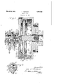
Figure 1 is a longitudinal sectional view of an air cylinder embodying my improved features; and
Figure 2 is a sectional view taken on the line 22 of Figure 1.
The air cylinder 3 as shown in these drawings is adapted to be secured to the machine with which it is to be used in the usual manner so that it rotates with the chuck (not shown) or other device which is actuated 35 thereb The cylinder 3 has a head 4 at one end w ich is preferablv formed integrally therewith and a removable head 5 at the opposite end which is held by studs or bolts 6. The head 5 is rovided with a hub 7 having a spindle or s aft 8 securely fitted therein. The spindle 8 is provided with a head 9 at its inner end and is threaded at its outer end to receive a correspondingly threaded collar or bearing 10 having an outwardly project 5 ing flange 11. A sleeve or housing 12 is mounted on the hub 7 and collar 10 and is preferably carried on ball bearings 13 and 14.
This sleeve is preferably made in two parts for constructional and assembling purposes,
these parts being held together by screws or bolts 15. The spindle 8 is threaded intermediate of its bearings to receive a corres ndingly threaded ring or collar 16 whic divides the space in the housin 12 into two annular chambers 17 and 18. The chamber 17 has a port 19 which connects with a ipe 20 which is threaded to engage with a s on the housing. The chamber 18 also has a ort 21 which connects with a pipe 22 whi is threaded to engage with another boss on the housing 12. The pipes 20 and 22 are connected with the source of supply of compressed air in the usual manner, the arrangement being such that when air is admitted through one pipe, it will be exhausted through the other pipe, and vice versa so that each pipe or inlet acts both as an intake and as an exhaust.
The chamber 17' is connected by means of a port or passageway 23 through the spindle 8 with one end of the cylinder 3.
The chamber 18 is connected by a port or passageway 24; through the spindle 8, with a port or passageway 25 which leads through the cylinder head 5 and outer wall of the cylinder to the opposite end of the cylinder.
The cylinder is provided with a iston 26 having a piston rod 27 which is a apted to be connected with the draw rod of the chuck or to any other device to be actuated thereby. The outer surface or periphery of the piston has two annular grooves 28 and 29 which connect respectively with narrower grooves 30 and 31. Holes 32 and 33 lead from the latter grooves to the correspondin sides of the piston, as will be readily seen rom Figure 1. Rings or hands 34 and 35 fit closely within the grooves 28 and 29 and rest a ainst the shoulders formed at the junction 0 these grooves with the narrower grooves 30 and 31. These rings or bands may be made of any suitable material but are preferably made of rubber or rubber composition. The remaining spaces in the grooves 28 and 29 are filled with packing rings 36 and 37, which may be made of any suitable packing materials and which en age with the inner wall of the cylinder. t will be seen that with this arrangement when air is admitted on either side of the piston, it will pass through the corresponding holes of the inner groove and will tend to force the band or ring rings or land construction shown.
The piston rod 27 passes through the hub 38 and is provided with the novel packing me or the cylinder so that the air may enter such slots and will tend to press the tapered or thin engaging portion of the ring against the rod. These packing rings are held by means of a threaded ring 41 which engages with the hub and is adapted to press them together and against the rod.
In an apparatus of this kind, the air pipes and the sleeve or housing with which they are connected must, of course, remain stationary while the cylinder rotates at comparatively high speed. On account of having to admit air under comparatlvely high pressure to the cylinder and also to exhaust air therefrom through such moving and stationary parts, it has been found very difficult to prevent leakage of the air or to provide packing which will last for any considerable length of time. One of the particularly important features of this invention is the arrangement of sealing these relatively moving and stationary parts or providing packing for the joints which will effectively prevent the loss of air and which will be apt to last for a considerable length of time. It will be seen that the joint or opening 42 between the collar 10 and the lnwardly extending flange or projection 43 at the end of the chamber 18 is approximately midway between the surface of the spindle and the outer wall of the chamber. In order to make this an air-tight joint, I provide a washer 44 which is preferably let into a roove 45 1n the housing 8 and fits closely against the oint or opening so as to cover or seal the same. This washer may be made of any suitable material but is preferably made of leather which I have found to be most satisfactory for this purpose. It will be seen that this washer practically forms an end for the chamber 18 and preferably remains stationary with the housing and is pressed against the adjacent end of the collar 10 by the air. The opposite end of the chamber 18 is provided with a similar washer 46, and the ends of the cham= ber 17 are provided with similar washers 47 and 48, but as these are all constructed and operate the same as the washer 44, further description will not be necessary.
When the cylinder is to be moved to the right, as shown in Figure 1, air is admitted through the pipe 20 to the chamber 17 and then passes through the port 23 to the left hand end of the cylinder and causes the piston to move to the right. At the same time the air in the right hand end of the cylinder is driven outwardly through the ports 25 and 24 to the chamber 18 and then escapes through the pipe 22. When the iston is to be moved to the left, the air will 0 course be conducted in the reverse directions. the ball bearings at each end of the housing tends to hold the housing and rotating parts in proper alignment so as to prevent bindin or friction or heating and thereby aids in increasing the operating life of the-parts, and particularly the packing devices.
These cylinders are made in various sizes for different kinds of work and changes ma be made in order to adapt the same for di ferent conditions, and therefore I do not wish to be limited to the exact arrangement herein shown and described, except as specifiedin the following claims, in which I claim:
1. The combination with a spindle for a rotatable I member having passageways for admitting air thereto and exhausting it therefrom, of a stationary housing having air passageways to coact with the spindle passageways, washers formed of leather or the like with their faces engaging with adjacent The provision of for closing the joints between such parts and bearings between the stationary and movable parts which are at a distance remote from the joints closed by said washers.
2. The combination with a spindle for a rotatable member adapted to receive air under pressure, said spindle having air ports therethrough, of a stationary housing mounted on said spindle, means coacting with the spindle and housing for forming chambers which are adapted to register with the ports in the spindle, said means including washers having flat faces which coact with adjacent portions of the movable and stationary parts to revent the escape of air, pipes connected wit said chambers and bearin s for said spindle at the ends of the housing yond said air-confining means.
3. The combination of a spindle for an air cylinder or the like, having air inlet and outlet ports, a stationary housing around the spindle having inwardly extending annular projections, projections on the spindle coacting with the projections on the housing to form two chambers around the spindle, washers engaging with grooves in the housing and covering the joints between the housing and spindle members, said chambers registering with the ports in the spindle, pipes leading to said chambers, and ball bearings at the ends of the housing.
4. In an apparatus of the character set forth, the combination of a stationary housing, a spindle projecting through said housing, ball bearings for said spindle arranged at either end of the housing to provide a relatively long bearing, air inlet and outlet passageways through the housing and spindle,
and packed joints arranged between the beatings whereby the packing closes .o that are difierent from those req by bearings. 5. T e combination with a sleeve, of a spindle rotatably mounted therein, coacting passageways through the sleeve and the spindle for the passage of ressure fluid 'oints between the sleeve an the spindle a jacent to the passagewa s, packin washers for closing said joints, an bearings tween the stationary and movable parts which are independent of the jointsand which are positioned at a suflieient distance from the joints to prevent heating at the joints.
LEO T.'NEIDOW.
Priority Applications (1)
| Application Number | Priority Date | Filing Date | Title |
|---|---|---|---|
| US168121A US1851723A (en) | 1927-02-14 | 1927-02-14 | Swivel joint |
Applications Claiming Priority (1)
| Application Number | Priority Date | Filing Date | Title |
|---|---|---|---|
| US168121A US1851723A (en) | 1927-02-14 | 1927-02-14 | Swivel joint |
Publications (1)
| Publication Number | Publication Date |
|---|---|
| US1851723A true US1851723A (en) | 1932-03-29 |
Family
ID=22610219
Family Applications (1)
| Application Number | Title | Priority Date | Filing Date |
|---|---|---|---|
| US168121A Expired - Lifetime US1851723A (en) | 1927-02-14 | 1927-02-14 | Swivel joint |
Country Status (1)
| Country | Link |
|---|---|
| US (1) | US1851723A (en) |
Cited By (22)
| Publication number | Priority date | Publication date | Assignee | Title |
|---|---|---|---|---|
| US2415181A (en) * | 1943-12-21 | 1947-02-04 | Gisholt Machine Co | Air cylinder |
| US2420626A (en) * | 1944-06-21 | 1947-05-13 | Merit Engineering Inc | Hydraulic servomotor with rotating cylinder and fluid transfer means adapted therefor |
| US2509673A (en) * | 1947-05-15 | 1950-05-30 | Union Mfg Co | Fluid pressure operated chuck |
| US2568092A (en) * | 1947-04-25 | 1951-09-18 | Cushman Chuck Co | Swivel connection for air operated chucks |
| US2620196A (en) * | 1948-02-14 | 1952-12-02 | Union Mfg Co | Pneumatic collet chuck closer |
| US2667302A (en) * | 1949-03-14 | 1954-01-26 | Westfalia Separator Ag | Centrifuge connection |
| US2723574A (en) * | 1950-07-19 | 1955-11-15 | Mueller Otto | Riveting device on slide operating independent riveting die |
| US2751230A (en) * | 1949-11-21 | 1956-06-19 | Korber Hans | Hydraulic chuck |
| US2758850A (en) * | 1950-12-15 | 1956-08-14 | Logansport Machine Co Inc | Rotating shaft and seal |
| US2823074A (en) * | 1956-12-11 | 1958-02-11 | Jr John E Bernard | Oxy-acetylene hose reel |
| US2835227A (en) * | 1953-03-09 | 1958-05-20 | Prec Ind | Hydraulic rotary distributor and its application to operating jacks for work-holdersof machine-tools |
| US2838028A (en) * | 1955-03-08 | 1958-06-10 | Daystrom Inc | Pneumatic follow-up system |
| US2849244A (en) * | 1955-12-19 | 1958-08-26 | Sp Mfg Corp | O-ring seal for rotary hydraulic cylinder |
| US2877026A (en) * | 1954-02-09 | 1959-03-10 | Crane Packing Co | Sealing device for a swivel joint having plural fluid passages |
| US2947553A (en) * | 1955-11-07 | 1960-08-02 | Daystrom Inc | Pipe coupling for a pneumatic follow-up system |
| US3021146A (en) * | 1958-01-10 | 1962-02-13 | Us Industries Inc | Seals |
| US3022770A (en) * | 1957-04-08 | 1962-02-27 | Sanders | Adjustable vaned rotor assemblies |
| US3175849A (en) * | 1959-11-18 | 1965-03-30 | White Sales Corp Graham | Rotary fluid coupling |
| DE1281784B (en) * | 1962-04-03 | 1968-10-31 | Forkardt Paul Kg | Pressure medium operated chuck |
| US3770305A (en) * | 1971-08-03 | 1973-11-06 | Riv Officine Di Villar Perosa | Device for conveying fluid into a rotatable hollow casing |
| US4111467A (en) * | 1976-04-13 | 1978-09-05 | N.V. Industrieele Handelscombinatie Holland | Rotatable coupling for a plurality of conduits, particularly for a buoy |
| US4339108A (en) * | 1980-05-05 | 1982-07-13 | Daniluk Philip M | Actuator for remotely operating a moving mechanism |
-
1927
- 1927-02-14 US US168121A patent/US1851723A/en not_active Expired - Lifetime
Cited By (22)
| Publication number | Priority date | Publication date | Assignee | Title |
|---|---|---|---|---|
| US2415181A (en) * | 1943-12-21 | 1947-02-04 | Gisholt Machine Co | Air cylinder |
| US2420626A (en) * | 1944-06-21 | 1947-05-13 | Merit Engineering Inc | Hydraulic servomotor with rotating cylinder and fluid transfer means adapted therefor |
| US2568092A (en) * | 1947-04-25 | 1951-09-18 | Cushman Chuck Co | Swivel connection for air operated chucks |
| US2509673A (en) * | 1947-05-15 | 1950-05-30 | Union Mfg Co | Fluid pressure operated chuck |
| US2620196A (en) * | 1948-02-14 | 1952-12-02 | Union Mfg Co | Pneumatic collet chuck closer |
| US2667302A (en) * | 1949-03-14 | 1954-01-26 | Westfalia Separator Ag | Centrifuge connection |
| US2751230A (en) * | 1949-11-21 | 1956-06-19 | Korber Hans | Hydraulic chuck |
| US2723574A (en) * | 1950-07-19 | 1955-11-15 | Mueller Otto | Riveting device on slide operating independent riveting die |
| US2758850A (en) * | 1950-12-15 | 1956-08-14 | Logansport Machine Co Inc | Rotating shaft and seal |
| US2835227A (en) * | 1953-03-09 | 1958-05-20 | Prec Ind | Hydraulic rotary distributor and its application to operating jacks for work-holdersof machine-tools |
| US2877026A (en) * | 1954-02-09 | 1959-03-10 | Crane Packing Co | Sealing device for a swivel joint having plural fluid passages |
| US2838028A (en) * | 1955-03-08 | 1958-06-10 | Daystrom Inc | Pneumatic follow-up system |
| US2947553A (en) * | 1955-11-07 | 1960-08-02 | Daystrom Inc | Pipe coupling for a pneumatic follow-up system |
| US2849244A (en) * | 1955-12-19 | 1958-08-26 | Sp Mfg Corp | O-ring seal for rotary hydraulic cylinder |
| US2823074A (en) * | 1956-12-11 | 1958-02-11 | Jr John E Bernard | Oxy-acetylene hose reel |
| US3022770A (en) * | 1957-04-08 | 1962-02-27 | Sanders | Adjustable vaned rotor assemblies |
| US3021146A (en) * | 1958-01-10 | 1962-02-13 | Us Industries Inc | Seals |
| US3175849A (en) * | 1959-11-18 | 1965-03-30 | White Sales Corp Graham | Rotary fluid coupling |
| DE1281784B (en) * | 1962-04-03 | 1968-10-31 | Forkardt Paul Kg | Pressure medium operated chuck |
| US3770305A (en) * | 1971-08-03 | 1973-11-06 | Riv Officine Di Villar Perosa | Device for conveying fluid into a rotatable hollow casing |
| US4111467A (en) * | 1976-04-13 | 1978-09-05 | N.V. Industrieele Handelscombinatie Holland | Rotatable coupling for a plurality of conduits, particularly for a buoy |
| US4339108A (en) * | 1980-05-05 | 1982-07-13 | Daniluk Philip M | Actuator for remotely operating a moving mechanism |
Similar Documents
| Publication | Publication Date | Title |
|---|---|---|
| US1851723A (en) | Swivel joint | |
| US2877026A (en) | Sealing device for a swivel joint having plural fluid passages | |
| US2568092A (en) | Swivel connection for air operated chucks | |
| US2462006A (en) | Rotary joint | |
| US2300385A (en) | Rotary shaft seal | |
| US2738996A (en) | Ring shaped sealing device | |
| US2547374A (en) | Rotary engine | |
| US2693373A (en) | Swivel connection for fluids | |
| US2429953A (en) | Shaft seal assembly | |
| US2229871A (en) | Valve mechanism | |
| US2633105A (en) | Vane type fluid motor | |
| US2598271A (en) | Servomotor with lubricated rotatable piston rod | |
| US2876948A (en) | Rotary air compressors | |
| GB726621A (en) | Improvements relating to liquid seals for gas-cooled dynamo electric machines | |
| US722219A (en) | Stuffing-box. | |
| US2336027A (en) | Lubricated valve | |
| US2407043A (en) | Air operated clutch | |
| US2781055A (en) | Apparatus for handling fluid | |
| US1760951A (en) | Rotary gate valve | |
| US2483521A (en) | Air suction clutch | |
| JPH08104415A (en) | Screw feeder | |
| US2079774A (en) | Balanced plug valve | |
| US790264A (en) | Rotary engine. | |
| US2851290A (en) | Axially compressible shaft seal | |
| US2350492A (en) | Steam joint |