US18516A - Operatieta railroad-shakes - Google Patents
Operatieta railroad-shakes Download PDFInfo
- Publication number
- US18516A US18516A US18516DA US18516A US 18516 A US18516 A US 18516A US 18516D A US18516D A US 18516DA US 18516 A US18516 A US 18516A
- Authority
- US
- United States
- Prior art keywords
- car
- rubbers
- brake
- wheels
- weight
- Prior art date
- Legal status (The legal status is an assumption and is not a legal conclusion. Google has not performed a legal analysis and makes no representation as to the accuracy of the status listed.)
- Expired - Lifetime
Links
Images
Classifications
-
- B—PERFORMING OPERATIONS; TRANSPORTING
- B61—RAILWAYS
- B61H—BRAKES OR OTHER RETARDING DEVICES SPECIALLY ADAPTED FOR RAIL VEHICLES; ARRANGEMENT OR DISPOSITION THEREOF IN RAIL VEHICLES
- B61H1/00—Applications or arrangements of brakes with a braking member or members co-operating with the periphery of the wheel rim, a drum or the like
Definitions
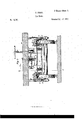
- My improvement is to be applied to the common eight-wheeled passenger and freight cars in use, which have springs, A, between the journal boxes, B, and the truck-frame, C; and which have the body or platform, D, mounted on the truck-frame either with, or, without, intervening springs to prevent jarring, or pendent bearings to allow lateral movement, of the car-body.
- the platform, D rests upon the truck frame, without intermediate springs.
- E, E are the usual bearings to keep the car-body from rocking sidewise.
- F, F are the ear-wheels.
- G is the king bolt.
- I-I, II are the brake-rubbersg-one being arranged over each carwheel, and each shaped internally to fit the tread of the wheels. These rubbers are firmly united together in pairs, corresponding with the sets of wheels, by bridges, I, as shown; and it is upon these rubbers that more or less of the weight of the car-body is shifted whenever the speed of the car is to be forcibly retarded.
- Springs, J lift the rubbers from the wheels when not overcome by the weight of the cai body.
- Stops, K are firmly secured to the truckframe to limit the upward movement of the brake-rubbers; and to keep the rubbers in place, and from turning with the car-wheels when forced against the latter.
- M is the brakemans common hand-wheel, having a fast-pulley or drum vN.
- a strong screw, O is firmly secured, in a vertical position, to the bottom of the car-body.
- a nut, P is tted to run up and down on each screw, and extends down to the bridge I.
- the nuts P are pulleys; and a chain, Q, is wound on them all, and also upon the pulley N of the hand-wheel in such manner that the brakeman, by turning the hand wheel in one direction, runs the nuts down on the screws O so as to first push the brake-rubbers down upon the car-wheels, and then gradually transfer any required portion of the weight of the car-body, from the truck frame, and consequently from the springs A, to t-he brake-rubbers, and thereby, to the top surface of the car-wheels; and, by turning the hand-wheel in the other direction, runs the nuts up on the screws so as to release the brake-rubbers, and, car-wheels.
Landscapes
- Engineering & Computer Science (AREA)
- Mechanical Engineering (AREA)
- Braking Arrangements (AREA)
Description
. ,A zsm-SM1. P. PERRY. ees ee Y Car Brake.
No. 18,516. I PatentedA Oct. 27, 1857'.
NITED `STATES PATENT OFFICE.
PHILANDER PERRY, OF TROY, NEIV YORK.
OPERATING RAILROAD-BRAKES.
Specification of Letters Patent No. 18,516, dated October 2'?, 1857.
To all whom t may Concern.'
Be it known that I, PHILANDER PERRY, of the cit-y of Troy, in the county of Rensselaer and State of New York, have invented a new and useful improvementin that kind of railroad-ear brake heretofore made wherein the weight of the car-body alone is applied to press brake-rubbers against the tops of the car wheels to retard t-he motion of the car, the weight of the truck-frame being constantly sustained by the journals of the caraxles; and I do hereby declare that the following is a full, clear, and exact description of' my invent-ion, reference being had to the annexed drawings, making a part of this` specification, in which- Figure l is a longitudinal, sectional elevation of one of the trucks of a car, with part of the platform or carbody; and of the means which I employ to shift any required portion of the weight of the car-body on and ofi' the brake-rubbersg-also showing my mode of arranging springs to prevent jolting and jarring of the car-body while the brake-rubbers are pressed upon the carwheels by its weight ,-the section being made at the line z y in Fig. 2, and viewed in the direction pointed by the arrow and Fig. 2 is a transverse sectional elevation of the same,-the section being made at the line fw o in Fig. l, and seen in the direction indicated by the arrow fw.
The same letters refer to like parts in both figures; and the arrows thereon indicate the directions in which the parts move.
My improvement is to be applied to the common eight-wheeled passenger and freight cars in use, which have springs, A, between the journal boxes, B, and the truck-frame, C; and which have the body or platform, D, mounted on the truck-frame either with, or, without, intervening springs to prevent jarring, or pendent bearings to allow lateral movement, of the car-body. In `the draw ings, annexed, the platform, D, rests upon the truck frame, without intermediate springs.
E, E, are the usual bearings to keep the car-body from rocking sidewise.
F, F, are the ear-wheels.
G is the king bolt.
I-I, II, are the brake-rubbersg-one being arranged over each carwheel, and each shaped internally to fit the tread of the wheels. These rubbers are firmly united together in pairs, corresponding with the sets of wheels, by bridges, I, as shown; and it is upon these rubbers that more or less of the weight of the car-body is shifted whenever the speed of the car is to be forcibly retarded. Springs, J, lift the rubbers from the wheels when not overcome by the weight of the cai body.
In Fig. l the car is running in the direction pointed by the arrow t,-with the brake rubbers pressed against the wheels; but in Fig. 2 the rubbers are seen lifted up.
Stops, K, are firmly secured to the truckframe to limit the upward movement of the brake-rubbers; and to keep the rubbers in place, and from turning with the car-wheels when forced against the latter.
M is the brakemans common hand-wheel, having a fast-pulley or drum vN.
Directly over each bridge I, of a pair of rubbers, a strong screw, O, is firmly secured, in a vertical position, to the bottom of the car-body. A nut, P, is tted to run up and down on each screw, and extends down to the bridge I. The nuts P are pulleys; and a chain, Q, is wound on them all, and also upon the pulley N of the hand-wheel in such manner that the brakeman, by turning the hand wheel in one direction, runs the nuts down on the screws O so as to first push the brake-rubbers down upon the car-wheels, and then gradually transfer any required portion of the weight of the car-body, from the truck frame, and consequently from the springs A, to t-he brake-rubbers, and thereby, to the top surface of the car-wheels; and, by turning the hand-wheel in the other direction, runs the nuts up on the screws so as to release the brake-rubbers, and, car-wheels.
Instead of arranging but one nut and screw to work each pair of brake-rubbers, I use two to each bridge whenever desirable, one near each end, as at s and s; t-he screws being all worked simultaneously by the hand-wheel and chain, to brake, and unbrake. The hand-wheel-chains may eX- tend around and operate all the brake screws of the two trucks of the car.
By the use of the sets of nuts and screws arranged upon the bottom of the car-body, worked by the hand-wheel-chain, and operating the pairs of brake-rubbers, as set forth, I attain advantageous results which I believe have not been heretofore secured by the use of analogous devices; for by this construction the brakeman, by means of the common hand-wheel, shifts any required Cil portion of the weight of only the car-body, upon and o from the pairs of brake-rubbers, arranged over the wheels as described, with equal ease, whichever way the car is ruiming ,-no force being exerted, in shifting the weight of the car-body on and offv the brake-rubbers, tending to press the brake-rubbers in the same direction with, or in the oppsite one, to that in which the car-wheels are turning,-as there is in S. K. Goodales model (at the Patent Office,) which has wedges sliding longitudinally in t-he bottom of the car-body to shift the weight of the car-body on and olf a frame of four brake-rubbers, over the car wheels.
To prevent jolting and jarring of the bodies of passenger and other cars while the vbrake-rubbers remain pressed against the slides up and down between guides c, c, fast on the brake-rubbers.the vupward motion being limited by the stops, d, on the brakerubbers. These springs, R, also serve to lessen the difficulty, or increase the ease, with which the weight of the car-body is brought to bear upon the brake-rubbers;- for the springs yield under pressure so that the hand-wheel is turned farther, t0 bring a given weight upon the rubbers, when the springs are employed in the manner set forth, than when they are absent.
What I claim as my invention and desire to secure by Let-ters Patent is,
1. The use of the sets of nuts and screws arranged upon t-he under side of the carbody, worked by the hand-wheel and chain, and operating upon the pairs of brake-rubbers, as herein described, for the purposes specified.
2. I also claim arranging springs, R, between the bottom of the ear-body and the brake-rubbers, as described; so as to prevent jolting or jarring of the (car-body while its weight presses the brake-rubbers upon the top of the car-wheels, and also t-o facilitate the application of the brake-rubbers, as specified.
PHILANDER PERRY.
Witnesses MORRIS CORNWELL, L. P. GoLDsMrrI-L
Publications (1)
| Publication Number | Publication Date |
|---|---|
| US18516A true US18516A (en) | 1857-10-27 |
Family
ID=2081897
Family Applications (1)
| Application Number | Title | Priority Date | Filing Date |
|---|---|---|---|
| US18516D Expired - Lifetime US18516A (en) | Operatieta railroad-shakes |
Country Status (1)
| Country | Link |
|---|---|
| US (1) | US18516A (en) |
-
0
- US US18516D patent/US18516A/en not_active Expired - Lifetime
Similar Documents
| Publication | Publication Date | Title |
|---|---|---|
| US18516A (en) | Operatieta railroad-shakes | |
| RU93764U1 (en) | Three-element truck of wagons | |
| US6273A (en) | Leverett tread well | |
| US409266A (en) | William r | |
| US135017A (en) | Improvement in railway-car brakes | |
| US114328A (en) | Improvement in apparatus for lifting locomotives, trucks, and railroad cars | |
| US1346171A (en) | Car-brake | |
| US961098A (en) | Skidding device for railway-cars. | |
| US2811112A (en) | Small-size shunting machine | |
| US94874A (en) | Lancelot davidson | |
| US264948A (en) | Street-car | |
| US12552A (en) | Railroad-car brake | |
| US162340A (en) | Improvement in car-brakes | |
| US145468A (en) | Improvement in car-starters | |
| US106412A (en) | Improvement in railway-car brakes | |
| US62127A (en) | Abraham gregg | |
| US99678A (en) | Improved railway-car brake | |
| US26117A (en) | Mode oe operating brakes on railroad-cars | |
| US123033A (en) | Improvement in car-brakes | |
| US345320A (en) | Railway-car brake | |
| US229747A (en) | Peters | |
| US143516A (en) | James s | |
| US20769A (en) | Railroad-car brake | |
| US9224A (en) | Bailboad-truck | |
| US19223A (en) | Railroad-cab brake |