US1851677A - Stapling mechanism - Google Patents
Stapling mechanism Download PDFInfo
- Publication number
- US1851677A US1851677A US459575A US45957530A US1851677A US 1851677 A US1851677 A US 1851677A US 459575 A US459575 A US 459575A US 45957530 A US45957530 A US 45957530A US 1851677 A US1851677 A US 1851677A
- Authority
- US
- United States
- Prior art keywords
- lever
- bending
- staple
- die
- wire
- Prior art date
- Legal status (The legal status is an assumption and is not a legal conclusion. Google has not performed a legal analysis and makes no representation as to the accuracy of the status listed.)
- Expired - Lifetime
Links
- 238000005452 bending Methods 0.000 description 117
- 239000000463 material Substances 0.000 description 9
- 238000010276 construction Methods 0.000 description 5
- 210000003414 extremity Anatomy 0.000 description 5
- 230000000717 retained effect Effects 0.000 description 5
- 230000000881 depressing effect Effects 0.000 description 4
- 230000015572 biosynthetic process Effects 0.000 description 3
- 230000037431 insertion Effects 0.000 description 3
- 238000003780 insertion Methods 0.000 description 3
- 230000003247 decreasing effect Effects 0.000 description 2
- 230000000994 depressogenic effect Effects 0.000 description 2
- 230000014509 gene expression Effects 0.000 description 2
- 230000002441 reversible effect Effects 0.000 description 2
- 229940000425 combination drug Drugs 0.000 description 1
- 238000006073 displacement reaction Methods 0.000 description 1
- VKYKSIONXSXAKP-UHFFFAOYSA-N hexamethylenetetramine Chemical compound C1N(C2)CN3CN1CN2C3 VKYKSIONXSXAKP-UHFFFAOYSA-N 0.000 description 1
- 239000007937 lozenge Substances 0.000 description 1
- 230000003534 oscillatory effect Effects 0.000 description 1
- 238000005096 rolling process Methods 0.000 description 1
- 210000000707 wrist Anatomy 0.000 description 1
Images
Classifications
-
- B—PERFORMING OPERATIONS; TRANSPORTING
- B27—WORKING OR PRESERVING WOOD OR SIMILAR MATERIAL; NAILING OR STAPLING MACHINES IN GENERAL
- B27F—DOVETAILED WORK; TENONS; SLOTTING MACHINES FOR WOOD OR SIMILAR MATERIAL; NAILING OR STAPLING MACHINES
- B27F7/00—Nailing or stapling; Nailed or stapled work
- B27F7/17—Stapling machines
- B27F7/26—Stapling machines without provision for bending the ends of the staples on to the work
- B27F7/28—Stapling machines without provision for bending the ends of the staples on to the work with means for forming the staples in the machine
Definitions
- This invention relates to stapling mechanism, and more particularly to mechanism for forming and inserting staples at high speed, suitable for use in machines for closing flex- B'ible containers or the like, although the invention is also capable of use in a wide variety of other stapling operations.
- Another object. of this invention is to provide a stapling mechanism which is readily -adjustable to form and introduce staples of various lengths.
- Another object of this invention' is to provide a staplin mechanism wherein the staple is formed and advanced into position for insertion by parts having relatively short working strokes of simple character so that the mechanism may operate at relatively high speed, and the time interval between successive insertions of staples may be reduced, and
- a single stapler may introduce all of the staples thathave heretofore required the use of a bank of staplers.
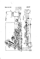
- FIG. 1 is a plan view of an embodiment of the present invention
- Fig. 2 is a side elevation of the stapling mechanism of Fig. 1;
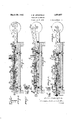
- Figs. 3, 4 and 5 are longitudinal sections through the staple forming and inserting mechanism to illustrate the relative positions 1930.
- Figs. .6, 7 and 8 are diagrammatic views, corresponding with Figs. 3, 4 and 5 respectively, to illustrate the formation and feeding of the staples at the several stages;
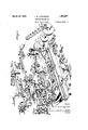
- Fig. 9 is a perspective view of the component elements of the stapling mechanism drawn apart for the purpose of showing their individual constructions and relative locations.
- the stapling mechanism is mounted on a base plate 10 ofany suitable size, construction and material. At one end of said base plate there is attached thereto or formed thereon a housing 11 for the bearing of a countershaft 12, here shown as carrying a pulley 13. designed to be driven from any suitable source of power, but if preferredthe countershaft may be driven by .pinions or in any other suitable manner,
- a crank 14 mounted on the countershaft 12 is a crank 14, here shown as in the form of a disk, provided with an eccentric crank pin 15.
- ed on the crank pin 15 is a connecting rod 16 of any suitable construction and connected by wrist pin 17 with across head 18 which slides in a channel-shaped way 19 integrally formed on or suitably attached to the base plate 10.
- a channelshaped staple bending head 36 which is attached to the body of the member 21 forwardly of said slot 33 in any suitable way, as by the screw 37.
- the forward bifurcated ends of said head 36 are provided at their. lower forward edges with notches 38 for a purpose hereinafter explained.
- extension 43 mounted for rectilinear movement at the forward end of the channel 22 .
- a chanpresser head 42 having a rearward extension 43 that is adapted to slide on the bottom of the channel 22, said extension 43 having a slot 44 in one of its side edges which provides forward and rearward stop shoulders 45 and 46 for a purpose to be hereinafter explained.
- the upper face of extension 43 is provided with a pair of spaced hemispherical depressions 47 and 48 for cooperation with the spring-pressed ball 31 as explained more in detail hereinafter.
- the inner lateral faces of the channel-shaped head 42 are provided with longitudinally extending ooves 49 to receive the ribs 41 on the sides 0 the drivin' head 40, said grooves 49 also providing gui es for the legs of the staple as it is advanced into position for in sertion by said driving head.
- the rearward portions of the sides of the head. 42 are cut away as shown at 50, as are also the walls between the grooves 49 and the surfaces 50 so the lateral wall at the bottom of each groove 49 projects outwardly to a greater extent than the top lateral wall.
- a lever 51 carrying a die block 52 Pivotally mounted above the channel 22 is a lever 51 carrying a die block 52, shown as separately formed and attached thereto, but said block could be formed integrally with the lever 51 if preferred. Said lever is mounted in position in any suitable way.
- a plate 53 is attached in any suitable way, as by screws 53, to the top edges of the channel way 19 or in a depression therein as indicated at54 (Fig. 9) and carries a pair of bearing lugs 55 which have apertures 56 through which and an aperture 57 in the lever 51 projects a pivot pin 58 that may be secured in position in any suitable way as by a. set screw 59.
- Lever 51 operates in the slots 62 which receive the upwardly extending sides 63 of the die -head 52, said head 52 being secured to the lever 51 in any suit-;
- Die head 52 has a transverse slot 65 extending from one side thereof to the other, and at its underside said head is shouldered as shown at 66, to form a die 67 forwardly of the slot 65. Above said shoulders 66 the head 52 is of a width to enter between the cutaway portions at the rear of the head 42 until said shoulders 66 engage the outwardly extending ledges 67 formed by the projecting lower lateral faces ofthe' grooves 49.
- said lever 51 is provided with an aperture 70 which receives a wear pin 71 projecting below the surface thereof for a purpose hereinafter explained. At its rearward extremity said lever is provided with a second aperture. 72 which receives an internally threaded sleeve 7 3 (Fig. 3) through which projects a pin 74 that acts as a cam follower as hereinafter explained.
- cam block 75 Mounted for slidable movement within the rearward portion of channel 22 is a cam block 75 having an upwardly projecting head 76 which has a forwardly beveled surface 77, and forward and rearward stop faces 78 and 79. Said head 76 is of the widthof the slot 23 in the member 21 and is designed to have relative movement to the member 21 within said slot 23.
- Cam block 75 is provided with means for frictionally retaining the same stationary at certain times and in predetermined position to the way 22 as the member 21 moves with respect thereto.
- said block carries a pin 80 projecting on either side thereof, and slidably mounted on said pin 80 at each side of the block 75 is a plate'81 which is designed to bear against the corresponding side of the channel 22.
- Coil springs 82' are interposed between the block 75 and each of the-plates 81,3adjacent the forward and rearward ends of each plate, so that each plate is normally urged frictionally against'the side of the way 22 to grip said side frictionally so that the block 75 is retained at times in a desired position but may slide freely along the ates with the shoulders 45 and 46 to limit the forward and rearward movement of the presser head '42.
- a long forwardly projecting lever 86v Pivotally mounted on the base plate 10 at 85 is a long forwardly projecting lever 86v which carries the mechanism for cutting off I lengths of wire to be formed into staples.
- the forward portion of said head 91 is aper-' way, as by a set screw 103.
- the head of lever 101 has an aperture 104 which receives the pivot pin 93 to which it is suitably-attached as by a set screw 105.
- Adjacent its rear end, the cutter lever has formed thereon or attached thereto a lozenge-shaped cam element 106, shown as attached thereto by screws 107,
- cam element having upper and lower beveled cam faces 108 and 109 forpurposes to be explained.
- a feed lever 116 Pivotally mounted in a lateral lug 114 extendin from the lever 86, in an aperture 115 in said ug, is a feed lever 116, having an aperture 117 at its fulcrum which receives a collar.
- lever 116 is provided with a slot 122 which has two angularly related sections, section 123 which extends generally in the direction of the length of the lever and section- 124 which extends at an angle of approximately 30 to the section-123.
- ⁇ Vorking within the slot 123 is a rotary collar 125 mounted on the shank 126 of a pin 127 which is engaged in an aperture 128 in a block 129 which may slide back and forth between ways 130 formed on or suitably attached to the base plate 10.
- the upper end of the pin 127 is mounted inv the hub 131 at the forward end of a connect moved forwardly and rearwar'dly within the ways 130 by the connecting rod 132 and the lever 116 is moved around its pivot by'reason of the engagement of its cam slot 122 with the rotary collar 125 on the pin 127.
- connecting hub 131 is a boss 135 having an interiorly threaded aperture 136 which carries the pivot 137 of a cutter operating lever 138.
- Said lever 138 may, if preferred, be made in one piece, but by preference it is jointed about a vertical axis, the forward end 139 of said lever being mounted in a slot 140 in the body 138 of said lever on a vertical pivot pin 141 which passes through" apertures 142 in the sides of the slot 140 and an aperture 143 in the section 139 of said lever.
- a suitable spring 144 mounted on the body 138 of said lever, normally urges the section 139 thereof in an anticlockwise direction about its pivot 141 so as to hold the forward end of the section 139 in operative position, but permits said section 139 to yield in clockwise direction against the tension of the spring 144 in the event of need, so as to prevent breakage of the parts.
- the forward end of said section 139 carries by means of a pivot pin 145 a roller 146 which is designed to cooperate with "Ithe lozenge shaped cam element 106 heretofore described.
- roller 146 When the lever'138, 139 is moved forwardly the roller 146 passes under the lozengeshaped cam element 106, rolling on a ledge 148 formed on or sutiably attached to the channel way 19. Roller 146 engages the beveled surface 109 and raises the rear end of cutter lever 100, depressing its forward'cutter carrying end to sever a length of wire. The roller 146 then moves beyond the lozengeshaped cam element 106,.permitting the cutter lever 100 to fall into engagement with the ledge 148.
- lever 151 which may oscillate around its pivot screw 152.
- the forward end of said lever 151 has formed thereon or suitably attached 5 end of the lever 116 has an upstanding rojection 156 to which-is suitably attache as by screws 157, a wear plate 158 having an arcuate surface 159 which is opposed to the serrated surface 155 of the feed block.
- Lever 151 is urged to engage the serrated surface 155 with the wear platez159 by a coil s ring 160 attached at one end to the end 0 said lever 151 and at the opposite end to an u standing pin 161 which may be formed on t e,
- lever 116 or, as shown, is formed on one end of a second bell crank lever 162 pivoted on the lever 116 by means of the screw 163.
- a stop pin 164 limits the rotation of said lever 162 around its axis 163 in an anticlockwise direction, and a stop pin 165 may also be provided on the projection156 to limit the extent to which the lever 151 ma be moved around its axis 152 in an anticloc wise direction.
- Lever 116 is urged in a clockwise direction around its pivot 118 by means of a coil spring 170 which is attached to said lever at one end and to a pin 172 attached to an arcuate projection 17 3 formed on or attached to the 30 base plate 10.
- a wire When a wire is positioned between the feeds block 154 and the wear plate 159 it will be gripped by the serrated surface 155 to said wear plate 159, andas the lever 116 is oscillated in an anticlockwise 35 direction around its pivot 118 in the manner heretofore described, the wire will be fed forwardly through the aperture in the guide bushing 96 and into and through the slot in the'die head 52.
- a leaf. spring 17 5 is suitably attached as by screws 176, to a beveled face 177 at the forward end of the channel-shaped way 19.
- means are provided for adjusting the pivot of the feed lever 116, and also for simultaneously adjusting the position of the lever 86 65 and the cutting mechanism carried thereby so that the cutter will be withdrawn from the channel-shapedway member 19 by an amount approximately e ual to one half of the increase in the feed 0 the wire as represented by the increased movement of the lever 116.
- the lever 184 having a reduced portion 185 which is rotatably received in the slot 183 and a shoulder 186 and collar 187 at either end of said reduced portion, and spaced apart by a distance equal to the thickness of the lug 182, so that said screw 184 is held in position rotatably but against movement in the direction of its axis.
- the threaded extremity 188 of said screw 184 is received in the threaded aperture 181.
- the cutter 102 is withdrawn or advanced with respect to the channel-shaped way 19 to the end that the severed section of wire shall project by substantially, equ al amounts on either side of the die head 52, the resilient stop 175 yielding to the amount necessary to center the section of wire as it protrudes to a greater or lesser extent through said head 52.
- the extension 17 3 on the base plate 10 carries wire straightening mechanism of any suitable form.
- a plate 200 is attached to the extension 173 in any suitable way, as by screws 201, and carries a grooved roll 202 and a pair of opposed straightening rolls 203 mounted on spindles 204 and retained thereon in any suitableway as by nuts 205.
- Rolls 202, 203 lie in horizontal alignment so as to straighten the wire in a horizontal di-.
- a set of rolls for straightening the wire in a vertical direction is mounted on the extension 173, as by ablock 210 and plate 211 suitably attached thereto, as a set of rolls for straightening the wire in a vertical direction and shown as composed of a grooved roll 212 and a pair of straightening rolls 213 mounted orf spindles 214 carried by the plate 211- and secured thereon in any suitable way as by nuts 5 215. While the two sets of straightening rolls have been shown and referred to as operating in vertical and horizontal planes, such is not necessary as they could be arranged in any other suitable planes but preferably in planes which lie at an angle of 90 with respect to each other. However, any other suitable form of straightening mechanism maybe employed if desired.
- the wire is threaded between the straightening rolls 212 and 213, between the straightening rolls 202 and 203, between the wear plate 159 and feed block 154 and through the aperture in the guide bushing 96 carried by the forward end of the lever 86.
- the connecting rod 16 is operated from the crank pin to advance and withdraw the rectilinearly movable member 21.
- the connecting rod 132 carried thereby causes the connecting rod 132 to move forwardly and backwardly, and its forward end carrying pin 127 is caused to move in a rectilinear path by reason of the engagement of the block 128 in the. ways 129.
- the lever 116 As the roller 125 moves rearwardly, the lever 116 is moved in the reverse 5 direction and the wire, gripped between the serrated surface 155 and the wear plate 159, is advanced through the guide bushing 96 and into and through the slot in the die head 52 of the staple forming mechanism, 0 the end of the wire engaging the resilient stop 175 which is moved to the extent required by the feeding motion of the feed lever 116. Then as the lever 116 moves next in a clockwise direction its feed block 154 is again 55 moved into engagement with a fresh section 138,139 with its roller 146 held in engage ment with the ledge 148 by the spring 147.
- roller 146 engages the surface 109 of the cam element 106 and elevates the rear end of the ever 100 about its pivot 93, depressing its forward end carrying cutter 102 to sever the length of wire where it protrudes beyond the guide bushing 96. Roller 146 then passes beyond the cam element 106, and durin the return movement ofithe connecting ro 132 the roller 146 rolls up over the inclined surnecting rod 16 the bending head 36 attached thereto is advanced therewith until the notches 38 in the forwardly extendin legs thereof engage the severed section 0 wire and bend the ends of thewire forwardly about the die portion 67 of the head 52, with the legs of the staple lying in the notches 66 in sald head.
- the pin 74 remains on the top surface of the lug 76, said block again remaining stationary with respect to the member 21.
- the forward end of the slot 23 engages the forward shoulder 78 of the lug 76 and carries the block 75 rearwardly tofore therewith, thereby causing the pin 74 to ride off of the lug 76 and up onto t e wear plate 26 which has its upper surface in a plane higher than the top surface of the lu 76.
- the head 52 is moved downwar ly to a lower position, depressing the staple until it lies on the ledges 67 formed by the lower extendin surfaces at'the sides of the grooves 49.
- the forward end of the driving head 40 now engages the staple lying in the grooves 49 and forces the staple ahead of it and drives the staple into the article which is to receive the same.
- the spring-pressed ball 31 is in engagement in the rear depression 48 of the extension 43 of the presser block 42, so that said presser block 42 is advanced with the member 21 to press its forward end against the article to be stapled.
- therear shoulder 46 of the slot 44 engages the stop pin 86 and arrests further forward movement of the presser head, with its forward end pressed firmly against the article to be stapled, and ball 51 leaves the recess 48 and rolls on the surface of the extension 43.
- the member 21 advances with respect to the presser head 42 with the driving head 40 forcing the staple into the material to be stapled, it willbe unwire is fed forwardly during the rearward" stroke of said member 21, the wire which has been fed forwardly during the preceding cycle is severed durin the forward stroke of the member 21, the wire which has been severed during the preceding cycle is formed into a staple about the die head 52 by the bending head 36 during the forward stroke of the member 21, and then during the rearward stroke of the member 21 the formed staple is depressed into the grooves 49, and during each forward stroke of the member 21 the staple which has been formed during the precedlng cycle is advanced by the driving head 40, and the presser head 42 is advanced simultaneously therewith, to insert the staple into the article to be stapled.
- the machine may be run at relatively high speed and staples can be formed and inserted by one machine v the machine may be readily adjusted to form I staples of varying lengths and this means includes devices for adjusting the location of the cutter proport onately to the change in in length of the wire which is to be severed so that the staple "will be formed symmetrically with respect to the die head 52 whether the length of,the wire is increased or decreased.
- a stapling mechanism in combination with means for feeding and severing lengths of wire, a reciprocating member, bending and driving members movable therewith, a die member cooperating with said bending member to form a staple and thereafter movable to displace the formed staple into a plane substantiallyparallel with that in which it is formed and then into the path of the driving member, and cam mechanism for operating said die member;
- a stapling mechanism in combination with means for feeding and severing lengths of wire, a reciprocating member, bending and driving members movable therewith, a die member cooperating with the bending member to form a staple, then displacethe formed staple out of the bending .plane, and then position the staple in a plane substantially parallel to the bending plane and in' the path of the driving member, and cam mechanism for operating said die member.
- a stapling mechanism in combination with means for feeding and severing lengths of wire, a reciprocating member, bending and driving members movable therewith, a die member cooperating therewith, a lever carrying said die member, and means operated by the reciprocation of said first named member for moving said lever to position said die member in cooperative relationship successively with said bending member and said driving member, said last named means including a device with respect to which said first named member is movable for a art of its stroke.
- a stapling mechanism in combination with means for feeding and severing lengths of wire, a reciprocating member, bending and driving members movable therewith, a die member. cooperating therewith, a lever carrying said die member, and cam mechanism actuated by the reciprocation of said first named member for operating said lever successively to move said die member into cooperative relationship with said bending member, move said die member to dis-. place the formed staple out of the bending plane and then position the formed staple in the path of said driving member.
- a staplingmechanism in combina tion with means for feeding and severing lengths of wire, a reciprocating member, a bending member and a driving member movable therewith, a die member, a lever carrying said die member, and means operated by the reciprocation of said first named member for displacing said lever to variously position said die member to cooperate with said bending member, displace the formed staple into a substantially parallel plane out of the path of the advancing wire and then position said staple in a substantially parallel plane in the path of said driving member.
- a stapling mechanism in combination with means for feeding'and severing lengths of wire, a die member, a bending member 00- operating therewith to bend a section of wire into a staple, a driving member, means to move said die member to displace a formed staple from the bending plane into an adjacent plane while a new section of wire is moving into cooperative relation with said die member and thereafter moving said formed staple mto another plane adjacent the driving member for driving the staple in said last named lane, and a reciprocating member for displacing said die member and operating said bending member and driving member.
- a stapling mechanism in combination with means for feeding and severing lengths of wire, a die member, a bending member cooperating therewith to bend a section of wire into a staple, means for moving the formed staple into a plane adjacent to the bending plane and retaining it therein while the next section of wire is moving into cooperative relation with said die member, means for moving the formed staple. into a third adjacent plane, and means for driving staples in said last named plane.
- a stapling mechanism in combinatidn with means for feeding and severing lengths of wire, means for forming a staple in one plane, means for displacing the formed staple into an adjacent parallel plane and retaining it therein out of the path of the advancing wire, driving means operating in atbiard plane parallel and adjacent to said second named plane, means for displacing said lengths of wire, a reciprocating member,
- a reciprocating member In a stapling mechanism, a reciprocating member, a bending member and a driving operating with said bending member to form a staple and then displace it from the bendstroke.
- a diemember In a stapling mechanism, a diemember, a bending member cooperating therewith to form a staple, a driving member for moving the staple in a plane contiguous to theforming plane, a reciprocating member for operating said driyin member and said bending member, a lever or moving said die member to displace the formed staple from the bending plane to the driving plane, and cam mechanism associated with said reciprocating member for operating said lever adjacent the end'of each stroke of said reciproeating member.
- a member for drivin formed staples In a stapling mechanism, a member for drivin formed staples, a'bending member movab e with said driving member, and a die member cooperatin with said bending member to form a stap e and movable to thereafter displace the formed staple onto said di'iving member and then into the path there- 0 18.
- a member for driving formed staples In a stapling mechanism, a member for driving formed staples, a bending member movable with said driving member, a die member cooperating vwith said bending member to form a staple, and cam means to displace said die member to move the formed staple onto the driving member and then into the path thereof.
- a member for driving formed staples a bending member movable with said-driving member, a die member cooperating with said bending member to form a staple, means to move said die member to displace the formed staple onto and then into t e path of said driving membet, and a reciprocating member for operating said drivin member, said bending memher, and said die member.
- a stapling mechanism a member for driving formed staples, a bending member movable with said driving member, a? die member cooperating with said bending member to form a staple, means for displacing said die member to position the formed staple in 1 the path of the drivingwmember, a lever carrying said die mem r, cam mechanism brought into operation adjacent each end of the movement of said driving member for operating said lever; and a reciprocating l member for operating said driving and bending members and said cam mechanism.
- a member for driving formed staples a member for driving formed staples
- a bending member movable with said driving member
- a die member cooperating with said bending memher to form a staple
- means for feeding lengths of wire to said die member a lever on which said die member is mounted, cam mechanism for moving said lever to displace a formed staple and retain it out of the path of the advancing wire-and then move it into the path of the driving member, and a reciprocating member for operating said driving and bending members and said cam mechanism.
- a member for driving formed staples a member for driving formed staples
- a bending member movable with said driving member
- a die member cooperating with said bending member
- means for feeding lengths of wire into cooperative relation with said die member means for displacing said die member to move a formed staple first out of the path of the advancing wire and subsequently into the path of 'said driving member, and a reciprocating member for operating said driving, bending and die members.
- a stapling mechanism In a stapling mechanism, a channelshaped way having a grooved end portion through which formed staples may be guided and driven, a reciprocating member for driving formed staples through said grooves, a bending member movable with said driving member, a die member cooperating with said driving member, means for feeding wire to said die member, and means for successively positioning said die member to receive the wire, form the wire into a staple by cooper ation with said bending member, displace the staple laterally out of the path of the advancing wire and subsequently displace the formed staple into the path of said driving member.
- a stapling mechanism In a stapling mechanism, a channelshaped' way having a grooved end portion through which formed staples may be guided and driven, a reciprocating member for driving staples through said grooves, a bending member movable with said driving member, a die member cooperating with said driving member, means for feeding wire to said die member, a lever on which said die member is mounted, and cam mechanism for operating said lever and including a cam device alternately movable with and retained stationary relative to said reciprocating member, said cam mechanism cooperating with said lever for displacing said die member into cooperative relation with said bending member and then moving the formed staple transversely of its length into thev path of "said reciprocating member.
- a stapling mechanism a channelshaped way provided at one end with grooves through which formed staples may be guided and driven, a reciprocating member for driving staples through said grooves, a bending member movable therewith, a movable die member cooperating with said bending member, means for feeding lengths of wire to said die member, and means to move said die member substantially at right angles to the directi on of movement of said. reciprocating member to first position said die member in cooperative relation with said bending member and then d splace the formed staple into an adjacent plane and subsequently into the path of said reciprocating member.
- a stapling mechanism In a stapling mechanism, a channelshaped way provided at one end with grooves through which formed staples may be guided and driven, a reciprocating member for driving staples through said grooves, a bending member movable therewith, a movable die member cooperating with said bending member, means for feeding lengths of wire to said die member. means to move said die member substantially at right angles to the direction of movement of said reciprocating member to first position said die member in cooperative relaton with said bending member and then displace the formed staple first onto and then into the path of said reciprocating member, and cam mechanism operated by said reciprogiting member for displacing said die mem- 27'.
- a reciprocating member for driving staples a bending member movable therewith, a movable die member cooperating with said bending member, means for feeding lengths of wire to said die member, means to move said die member substantially at right angles to the direction of movement of said reciprocating member to first position said die member in cooperative relation with said bending member, then displace the staple out of the plane in which it is formed and then displace the formed staple into the path of said reciprocating member, and a presser member operated by said reciprocating member to compact the material into which the staple is to be inserted.
- a reciprocating member for driving staples a bending member movable therewith, a movable die member cooperating with said bending member, means for feeding lengths'of wire to said die member, means to move said die member substantially at right angles to the direction of movement of said reciprocating member to first position said die member in cooperative relation with said bending member and then displace the formed staple into the path of said reciprocating member, a presser member for compressing the material into which the staple is ,to be inserted, and means between said reciprocating member and said presser member for moving said presser member into operative position at the beginning of the-driving stroke and withdrawing said member movable therewith, a movable die' member cooperating with said bending member, means for feeding lengths of wire to said die member, means to move said die member substantially at right angles to the direction of movement of said reciprocating member to first position said die member in cooperative relation with said bending member and then displace the formed staple into the path of said reciprocating member, a
- a reciprocating member vfor driving staples a bending member movable therewith, a movable die member cooperating with said bendng mem ber, means for feeding lengths of wire to said die member,means to move said die member substantially at right angles to the direction of movement of said reciprocating member to first position said die member in cooperative relation with said bending member and then displace the formed staple into the path of said reciprocating member, a cutter for severing lengths of wire, and a lever operated by the movement of said reciprocating member for operating saidcutter.
- a reciprocating member for driving staples a bending member movable therewith, a movable die member cooperating with said bending member, means for feeding lengths of wire to said die member, means to move said die member substantially at right angles to the direction of movement of said reciprocating member to first position said die member in cooperative relation with said bending member and then displace the formed staple into the path of said reciprocating member.
- a lever carrying a cutter and a cam a rectilinearly movable member for operating said inoperative by said cam during its return stroke, and means 0 crating said rectilinearly movable member ii'om said reciprocating member.
- a reciprocating rnember for driving staples a bending member movable therewith, a movable die member cooperating with said bending member, means to move said die member substantially at right angles to the direction of lever during its forward stroke and rendered movement of said reciprocating member to first position said die member in cooperative relation with said bending member and then displace theformed staple into the path of said reciprocating member, a wire feeding member, a rectilinearly movable member cooperating therewith for oscillating said wire feeding member, and means connecting said rectilinearly movable member and said reciprocating member whereby said Wire feeding'member is operated by said reciprocating member.
- a reciprocating member or driving staples a bending member movable therewith, a movable die member cooperating with said bending member, means to move said 'die member sub-- stantially at right angles to the direction of movement of said reciprocating member to first position said die member in cooperative relation with said bending member and then displace the formed staple into the path of said reciprocating member, a wire feeding member having a cam slot, a rectilinearly movable member cooperating with said slot, and means moving said rectilinearly movable member from ,said reciprocating member.
- a reciprocating member for driving staples a bending member movable therewith, a movable die member cooperating with said bending member, means to move said die member substantially at right angles to the direction of movement of said reciprocating member to first position said die member in cooperative relation with said bending member and then displace the formed staple into the path of said reciprocating member, wire feeding and severing levers unitarily movable about separate axes, a common means for adjusting said levers, and means moved by said reciprocating member for operating both of said levers.
- a reciprocating member for driving staples a bending member movable therewith, a movable die member cooperating with said bending member, means to move said die member substan tially at right angles to the direction of movement of said reciprocating member to first position said die member in cooperative relation with said bending member and then displace the formed staple into the path of said reciprocating member, a pivotally mounted support carrying a cutter lever, a wire feed lever pivotally mounted on said support, means operated by said reciprocating member for operating both of said levers, and means for adjusting said support and coopcrating therewith to produce twice as much movement of said feed lever as said cutter lever.
- a reciprocatber means to move said die member substantially at right angles to the direction of movement-of said reciprocating member to first position said die member in cooperative relation with said bending memberand then displace the formed staple into a contiguous parallel plane in the path of said reciprocating member, a wire feeding lever, a wire cutting lever, and means for operating said wire feeding and wire cutting levers from said reciprocating member so that said wire is fed and severed while the staples are being formed and fed in contiguous parallel planes.
- a reciprocating member for driving staples a bending member movable therewith, a movable die member cooperating with said bending member, means to move said die member substantially at right angles to the direction of movement of said reciprocating member to first position said die member in cooperative relation with said bending member and then dis lace the formed staple into the path of sai reciprocating member, a pivotally mounted support, a cutter lever pivotally mounted thereon, a wire feed lever pivotally mounted thereon, a rectilinearly movable member for operating said levers and connected to said reciprocating member to be operated thereby, and means for adjusting said support, said rectilinearly movable member cooperating with said wire feed lever to produce twice as much displacement thereof as of the cutter lever by movement of said support.
- a stapling mechanism a channelshaped way provided with grooves to guide formed staples, a reciprocating member for driving staples through said grooves and inserting the same, a bending member movable therewith, a die member adapted to cooperate with said bending member, a lever carrying said die member, cam mechanism for operating said lever to displace said die member and move a formed staple into the path of said reciprocating member and means for moving said cam mechanism into and out of cooperative relationship with said lever.
- a stapling mechanism a channelshaped way provided with grooves to guide formed staples, a reciprocating member for driving staples through said grooves and inserting the same, a bending member movable therewith, a die member adapted to cooperate with said bending member, a lever carrying said die member, and cam mechanism for operating said lever to displace said die member and move a formed staple into the path of said reciprocating member, said cam mechanism operating said die member to remove the formed staple out of the bending plane and into a arallel plane contiguous thereto during the ending stroke of said reciprocating member.
- a stapling mechanism In a stapling mechanism, a channel-- shaped way 1provided with grooves to guide formed stap es, a reciprocating member for driving staples through said grooves and inserting the same, a bending member movable therewith, a die member adapted to cooperate with said bending member, a lever carrying said die member, and cam mechanism for operating said lever to displace said die memher and move a formed staple into the path of said reciprocating member, said cam mechanism moving said die member to displace the formed staple onto the surface of said reciprocating member during the bending stroke thereof and then displacing said staple into the path of said reciprocating member when said reciprocating member has moved to the rear thereof during the reverse stroke.
- a stapling mechanism a member having a channel-shaped way provided with grooves to guide formed staples, a reciprocating member for driving staples through said grooves and inserting the same, a bending member movable therewith, a die member adapted to cooperate with said bending member, a lever carrying-said die member, cam mechanism for operating said lever to displace said die member and move a formed staple into the path of said reciprocating member, said channel-shaped way member acting as a presser member to compact the material into which the staple is to be in-' serted, and means for moving said channelshaped way member with said reciprocating member at the first portion of each stroke thereof.
- a stapling mechanism In a stapling mechanism, a channch shaped way provided with grooves to guide formed staples, a reciprocating member for driving staples through said grooves and in serting the same, a bending member movable therewith, a die member adapted to cooperate with said bending member, a lever carrying said die member, cam mechanism for operating said lever to displace said die member and move a formed staple into the path of said reciprocating member, a cam actuated cutter for severing lengths of wire, and a member moved by said reciprocating member for operating sa1d cutter during its forward stroke, said member being mo red to an inoperative position by said cam during the return stroke.
- a stapling mechanism alchannelshaped way provided with grooves to guide formed staples, a reciprocating member for driving staples through said. grooves and inserting the same, a bending member movable therewith, a die member adapted to cooperate with said bending member, a lever carrying said die member .cam mechanism for op erating said lever to displace said diamember and move aformed staple into the path of said reciprocating member, a wire feed lever for feeding lengths of wire to said die member, and a rectilinearly movable member operatedby said reciprocating member for e1 ating said lever to displace said die member and move a formed staple into the path of said reciprocating member, a pivotally mounted support carrying wire cutting and wire feeding devices, means for adjusting said support, and means whereby said adjustment produces twice as much movement of said 'wire feeding device as of said cutting device.
- a reciprocating member for driving staples a bending member movable therewith, a movable die member cooperating with said bending memher, a lever on which'said die member is mounted, and eam mechanism ositioned by said reciprocating member and t en held relatively stationary for operating said lever.
- a reciprocating member for member cooperating with sald bending memher a lever on which said'die member 1s mounted, cam mechanism intermittently operated by said reciprocating member for mov 'ing said lever, and a channel-shaped presser member having lateral grooves to ide a staple and intermittently movable w1th said reelprocating member to guide the staple wlrile said reciprocating member drives the I staple into the material to be stapled.
- reclproeating member for driving staples, a bending member movable therewith, a movable die member cooperating with said bending memher, a lever on which said die member is with said reciprocating member,.and means for yieldably loeking'said presser member to said reciprocating member for the first portion of each stroke whereby said presser member is moved to compact the material into riving staples, a bending I member movable therewith, a movable die which the staple is to be inserted while said reciprocating member drives the staple thereinto.
- a reciprocating member for-driving staples a bending member movable therewith, a movable die member cooperatin with said bending member, a lever on which said die member is mounted, cam mechanism operated by said re-' ciprocating member for moving said lever, a cutter-lever disposed parallel and adjacent to said reciprocating member, and a lever on said reciprocating member for operating said cutter member at each forward stroke of said reciprocating member.
- a reciprocating member or riving staples a bending member movable therewith, a movable die member cooperating with said bending member, a lever on which said die member is mounted, cam mechanism operated by said reciprocating member for moving said lever,
- a wire feeding lever movable transversely to said reciprocating member, a wire cutter,-operatin'g means for said wire cutter mounted on said wire feeding lever, and means operated by said reciprocating member for oscillating said wire feeding lever to feed lengths of wire to said die member during each backward stroke of said reci rocating member.
Landscapes
- Engineering & Computer Science (AREA)
- Mechanical Engineering (AREA)
- Life Sciences & Earth Sciences (AREA)
- Forests & Forestry (AREA)
- Portable Nailing Machines And Staplers (AREA)
Description
March 29-, 1 932.
I. W. LITCHFIELD STAPLING MECHANISM 3 Sheets-Sheet 1 March 1932. W.--LITCHFIELD STAPLING MECHANISM Filed June 6, 1930 3 Sheets-Sheet 2 March 29, 1932.. l. w. LITCHFIELD STAPLING MECHANISM Filed Juli; s, 1950 s Sheets-Sheet :5"
Patented Mar. 29, 1932 UNITED STATES PATENT OFFICE ISAAC W. LI'ICHFIELD, OF BOSTON,.MASSACHUSE'ITS, ASSIGNOR TO BEHIS BRO. BAG 00., OF NEW YORK, N. Y., A. CORPORATION OF MISSOURI STAPLING MECHANISM Application filed June 6,
This invention relates to stapling mechanism, and more particularly to mechanism for forming and inserting staples at high speed, suitable for use in machines for closing flex- B'ible containers or the like, although the invention is also capable of use in a wide variety of other stapling operations.
It is an object of this invention to rovide a stapling mechanism which is re atively simple, and also strong and durablein construction, and which is highly eflicient in operation. i
Another object. of this invention is to provide a stapling mechanism which is readily -adjustable to form and introduce staples of various lengths. I
Another object of this invention'is to provide a staplin mechanism wherein the staple is formed and advanced into position for insertion by parts having relatively short working strokes of simple character so that the mechanism may operate at relatively high speed, and the time interval between successive insertions of staples may be reduced, and
thereby a single stapler may introduce all of the staples thathave heretofore required the use of a bank of staplers.
Other objects of the invention will appear as the description of the invention proceeds.
This invention is capa le of receiving a variety of mechanical, expressions, one of which is shown on the accompanying drawings, but it is to be expressly understood that the drawings are for purposes of illustration only and are not to be construed as a definition of the limits of the invention, reference being had to the appended claims for that purpose.
Referring in detail to the drawings, wherein the same reference characters are employed to designate corresponding parts in the several figures Fig. 1 is a plan view of an embodiment of the present invention;
Fig. 2 is a side elevation of the stapling mechanism of Fig. 1; I
Figs. 3, 4 and 5 are longitudinal sections through the staple forming and inserting mechanism to illustrate the relative positions 1930. Serial No. 459,575.
of the tion;
Figs. .6, 7 and 8 are diagrammatic views, corresponding with Figs. 3, 4 and 5 respectively, to illustrate the formation and feeding of the staples at the several stages; and
Fig. 9 is a perspective view of the component elements of the stapling mechanism drawn apart for the purpose of showing their individual constructions and relative locations.
In the form shown, the stapling mechanism. is mounted on a base plate 10 ofany suitable size, construction and material. At one end of said base plate there is attached thereto or formed thereon a housing 11 for the bearing of a countershaft 12, here shown as carrying a pulley 13. designed to be driven from any suitable source of power, but if preferredthe countershaft may be driven by .pinions or in any other suitable manner, Mounted on the countershaft 12 is a crank 14, here shown as in the form of a disk, provided with an eccentric crank pin 15. ed on the crank pin 15 is a connecting rod 16 of any suitable construction and connected by wrist pin 17 with across head 18 which slides in a channel-shaped way 19 integrally formed on or suitably attached to the base plate 10.
'Suitablyattached to the cross head 18, as by the screw 20, is a rectilinearly movable parts at successive stages of the operamember 21 which has a slidin fit in the channel 22 of the way 19 and w ich carries the parts for forming and driving the staples as said member is reciprocated back and forth within the way 22 by the connecting rod 16. Adjacent the end of said member 21 connected to the cross head 18 said member 21 is slotted as shown at 23, and at its forward end said Oscillatably mount- 7 with its seat in. the end of the retainer 29 by I siliently ressed ball'operates as a yieldable nel-shaped latch as ereinafter explained. Forwardly of the aperture 28 member 21 is provided with a transverse slot 33, and at its forward extremity member 21 is provided with a forwardly extending ledge 34 of reduced width and height with respect to the body of,said member 21.
Mounted in the transverse slot 33 are the downwardly projecting lugs 35 of a channelshaped staple bending head 36 which is attached to the body of the member 21 forwardly of said slot 33 in any suitable way, as by the screw 37. The forward bifurcated ends of said head 36 are provided at their. lower forward edges with notches 38 for a purpose hereinafter explained. Mounted on the ledge 34 and attached thereto in any suitable way, as by screws 39,'is a staple driving head 40 provided with longitudinal ribs 41st both ed es thereof.
lso mounted for rectilinear movement at the forward end of the channel 22 .is a chanpresser head 42 having a rearward extension 43 that is adapted to slide on the bottom of the channel 22, said extension 43 having a slot 44 in one of its side edges which provides forward and rearward stop shoulders 45 and 46 for a purpose to be hereinafter explained. The upper face of extension 43 is provided with a pair of spaced hemispherical depressions 47 and 48 for cooperation with the spring-pressed ball 31 as explained more in detail hereinafter. The inner lateral faces of the channel-shaped head 42 are provided with longitudinally extending ooves 49 to receive the ribs 41 on the sides 0 the drivin' head 40, said grooves 49 also providing gui es for the legs of the staple as it is advanced into position for in sertion by said driving head. The rearward portions of the sides of the head. 42 are cut away as shown at 50, as are also the walls between the grooves 49 and the surfaces 50 so the lateral wall at the bottom of each groove 49 projects outwardly to a greater extent than the top lateral wall.
Pivotally mounted above the channel 22 is a lever 51 carrying a die block 52, shown as separately formed and attached thereto, but said block could be formed integrally with the lever 51 if preferred. Said lever is mounted in position in any suitable way. As
shown, a plate 53 is attached in any suitable way, as by screws 53, to the top edges of the channel way 19 or in a depression therein as indicated at54 (Fig. 9) and carries a pair of bearing lugs 55 which have apertures 56 through which and an aperture 57 in the lever 51 projects a pivot pin 58 that may be secured in position in any suitable way as by a. set screw 59. Lever 51 operates in the slots 62 which receive the upwardly extending sides 63 of the die -head 52, said head 52 being secured to the lever 51 in any suit-;
able way, as by a screw 64. Die head 52 has a transverse slot 65 extending from one side thereof to the other, and at its underside said head is shouldered as shown at 66, to form a die 67 forwardly of the slot 65. Above said shoulders 66 the head 52 is of a width to enter between the cutaway portions at the rear of the head 42 until said shoulders 66 engage the outwardly extending ledges 67 formed by the projecting lower lateral faces ofthe' grooves 49. Rearwardly of the pivot pin. 58 said lever 51 is provided with an aperture 70 which receives a wear pin 71 projecting below the surface thereof for a purpose hereinafter explained. At its rearward extremity said lever is provided with a second aperture. 72 which receives an internally threaded sleeve 7 3 (Fig. 3) through which projects a pin 74 that acts as a cam follower as hereinafter explained.
Mounted for slidable movement within the rearward portion of channel 22 is a cam block 75 having an upwardly projecting head 76 which has a forwardly beveled surface 77, and forward and rearward stop faces 78 and 79. Said head 76 is of the widthof the slot 23 in the member 21 and is designed to have relative movement to the member 21 within said slot 23. Cam block 75 is provided with means for frictionally retaining the same stationary at certain times and in predetermined position to the way 22 as the member 21 moves with respect thereto. To this end said block carries a pin 80 projecting on either side thereof, and slidably mounted on said pin 80 at each side of the block 75 is a plate'81 which is designed to bear against the corresponding side of the channel 22. Coil springs 82' are interposed between the block 75 and each of the-plates 81,3adjacent the forward and rearward ends of each plate, so that each plate is normally urged frictionally against'the side of the way 22 to grip said side frictionally so that the block 75 is retained at times in a desired position but may slide freely along the ates with the shoulders 45 and 46 to limit the forward and rearward movement of the presser head '42. I
Pivotally mounted on the base plate 10 at 85 is a long forwardly projecting lever 86v which carries the mechanism for cutting off I lengths of wire to be formed into staples.
vpasses through a knurled headed eccentric collar or sleeve 88 which is received in the aperture 89 in the end of the lever 86. Hence by rotating the collar or sleeve 88 with respect to the screw 87, the pivotal axis of said lever 86 may be given appropriate adjustment. Adjacent its forward end said lever 86 has formed thereon or attached thereto a block 91 having a transverse aperture 92 which receives the pivot screw 93 of the cutter lever.
- The forward portion of said head 91 is aper-' way, as by a set screw 103. The head of lever 101 has an aperture 104 which receives the pivot pin 93 to which it is suitably-attached as by a set screw 105. Adjacent its rear end, the cutter lever has formed thereon or attached thereto a lozenge-shaped cam element 106, shown as attached thereto by screws 107,
said cam element having upper and lower beveled cam faces 108 and 109 forpurposes to be explained.
Pivotally mounted in a lateral lug 114 extendin from the lever 86, in an aperture 115 in said ug, isa feed lever 116, having an aperture 117 at its fulcrum which receives a collar.
or sleeve 118 retained in position by a knurled headed screw 119 which passes through the aperture in said collar or sleeve and has its lower threaded end received in an adjusting device to be described. The rearward portion of lever 116 is provided with a slot 122 which has two angularly related sections, section 123 which extends generally in the direction of the length of the lever and section- 124 which extends at an angle of approximately 30 to the section-123. \Vorking within the slot 123 is a rotary collar 125 mounted on the shank 126 of a pin 127 which is engaged in an aperture 128 in a block 129 which may slide back and forth between ways 130 formed on or suitably attached to the base plate 10.
The upper end of the pin 127 is mounted inv the hub 131 at the forward end of a connect moved forwardly and rearwar'dly within the ways 130 by the connecting rod 132 and the lever 116 is moved around its pivot by'reason of the engagement of its cam slot 122 with the rotary collar 125 on the pin 127.
Projecting laterally from the head of the.
connecting hub 131 is a boss 135 having an interiorly threaded aperture 136 which carries the pivot 137 of a cutter operating lever 138. Said lever 138 may, if preferred, be made in one piece, but by preference it is jointed about a vertical axis, the forward end 139 of said lever being mounted in a slot 140 in the body 138 of said lever on a vertical pivot pin 141 which passes through" apertures 142 in the sides of the slot 140 and an aperture 143 in the section 139 of said lever. A suitable spring 144, mounted on the body 138 of said lever, normally urges the section 139 thereof in an anticlockwise direction about its pivot 141 so as to hold the forward end of the section 139 in operative position, but permits said section 139 to yield in clockwise direction against the tension of the spring 144 in the event of need, so as to prevent breakage of the parts. The forward end of said section 139 carries by means of a pivot pin 145 a roller 146 which is designed to cooperate with "Ithe lozenge shaped cam element 106 heretofore described. As the connecting rod 132 is moved forwardly and rearwardly with its pin 127 restrained to move in a rectilinear path by reason of the movement of the block 128 in the way 130, the lever 138. 139 is moved forwardly and rearwardly therewith, and is normally urged down- \vardly by a coil spring 147 which is wrapped around the boss 135 and has its opposite ends bearing on the upper surfaces of said boss and the body 138 of said lever.
When the lever'138, 139 is moved forwardly the roller 146 passes under the lozengeshaped cam element 106, rolling on a ledge 148 formed on or sutiably attached to the channel way 19. Roller 146 engages the beveled surface 109 and raises the rear end of cutter lever 100, depressing its forward'cutter carrying end to sever a length of wire. The roller 146 then moves beyond the lozengeshaped cam element 106,.permitting the cutter lever 100 to fall into engagement with the ledge 148. As the lever 138, 139 is moved rearwardly, the roller 146 r olls up the beveled surface 108 and over the top of the cam element 106 without operating said lever 100, then passing beyond said cam element, where-- upon said lever'138, 139 is depressed by'itsspring 147 to engage the roller 146 again with the ledge 148, where it is in position to co operate with the cam surface 109 and again operate the cutter lever 100 upon the next forward stroke of the lever 138, 139. v j
' Pivotally mounted on a boss 150 carried by the lever 116 at its forward end is a bell crank.
lever 151 which may oscillate around its pivot screw 152. The forward end of said lever 151 has formed thereon or suitably attached 5 end of the lever 116 has an upstanding rojection 156 to which-is suitably attache as by screws 157, a wear plate 158 having an arcuate surface 159 which is opposed to the serrated surface 155 of the feed block. Lever 151 is urged to engage the serrated surface 155 with the wear platez159 by a coil s ring 160 attached at one end to the end 0 said lever 151 and at the opposite end to an u standing pin 161 which may be formed on t e,
lever 116 or, as shown, is formed on one end of a second bell crank lever 162 pivoted on the lever 116 by means of the screw 163. A stop pin 164 limits the rotation of said lever 162 around its axis 163 in an anticlockwise direction, and a stop pin 165 may also be provided on the projection156 to limit the extent to which the lever 151 ma be moved around its axis 152 in an anticloc wise direction.
5 Lever 116is urged in a clockwise direction around its pivot 118 by means of a coil spring 170 which is attached to said lever at one end and to a pin 172 attached to an arcuate projection 17 3 formed on or attached to the 30 base plate 10. When a wire is positioned between the feeds block 154 and the wear plate 159 it will be gripped by the serrated surface 155 to said wear plate 159, andas the lever 116 is oscillated in an anticlockwise 35 direction around its pivot 118 in the manner heretofore described, the wire will be fed forwardly through the aperture in the guide bushing 96 and into and through the slot in the'die head 52. When the lever 116 moves in a clockwise direction around its pivot 118, however, the bell crank 151 will move around its pivot 152 against the tension of the spring 160 sufiiciently to release the grip of the serrated surface 155 on the wire, and permit the gripping surfaces 155, 159 to slide with respect to the wire until the lever 116 has reached the limit of its oscillatory motion in a clockwise direction, when the feed block 154 is again in position to grip the wire against the wear plate 159 and advance it at the next movement of the lever 116 in an anticlockwise direction.
In order to provide a yieldable stop for the end of the wire protruding through the slot 65, a leaf. spring 17 5 is suitably attached as by screws 176, to a beveled face 177 at the forward end of the channel-shaped way 19.
To provide for adjustment of the wire feeding mechanism, and also the cutting mecha- C3- nism, so that different lengths of wire may be severed to form staples of different lengths, means are provided for adjusting the pivot of the feed lever 116, and also for simultaneously adjusting the position of the lever 86 65 and the cutting mechanism carried thereby so that the cutter will be withdrawn from the channel-shapedway member 19 by an amount approximately e ual to one half of the increase in the feed 0 the wire as represented by the increased movement of the lever 116. Asheretofore explained, the lever 184 having a reduced portion 185 which is rotatably received in the slot 183 and a shoulder 186 and collar 187 at either end of said reduced portion, and spaced apart by a distance equal to the thickness of the lug 182, so that said screw 184 is held in position rotatably but against movement in the direction of its axis. The threaded extremity 188 of said screw 184 is received in the threaded aperture 181. Hence as said screw is rotated the pivot 118 of the lever 116 is moved toward or away from the channel-shaped way 19, and the lever 86 is simultaneously moved in the same direction, but as the lever 86 moves around the remote pivot 89, the amount of adjustment given to the cutter 102 carried by said lever 86 is approximately one half of the adjustment given to the forward end of the lever 116 and its cooperating feed block 154. Therefore, as the amount of wire advanced to form each staple is increased or decreased, the cutter 102 is withdrawn or advanced with respect to the channel-shaped way 19 to the end that the severed section of wire shall project by substantially, equ al amounts on either side of the die head 52, the resilient stop 175 yielding to the amount necessary to center the section of wire as it protrudes to a greater or lesser extent through said head 52.
As the wire from which the staples are formed is ordinarily fed from a roll, means are preferably provided in conjunction with the sta ling mechanism to straighten thewire be ore it is fed into the stapling mechanism proper. V In the form shown, the extension 17 3 on the base plate 10 carries wire straightening mechanism of any suitable form. As illustrated, a plate 200 is attached to the extension 173 in any suitable way, as by screws 201, and carries a grooved roll 202 and a pair of opposed straightening rolls 203 mounted on spindles 204 and retained thereon in any suitableway as by nuts 205. Rolls 202, 203 lie in horizontal alignment so as to straighten the wire in a horizontal di-.
rection. Also mounted on the extension 173, as by ablock 210 and plate 211 suitably attached thereto, is a set of rolls for straightening the wire in a vertical direction and shown as composed of a grooved roll 212 and a pair of straightening rolls 213 mounted orf spindles 214 carried by the plate 211- and secured thereon in any suitable way as by nuts 5 215. While the two sets of straightening rolls have been shown and referred to as operating in vertical and horizontal planes, such is not necessary as they could be arranged in any other suitable planes but preferably in planes which lie at an angle of 90 with respect to each other. However, any other suitable form of straightening mechanism maybe employed if desired. In operation, the wire is threaded between the straightening rolls 212 and 213, between the straightening rolls 202 and 203, between the wear plate 159 and feed block 154 and through the aperture in the guide bushing 96 carried by the forward end of the lever 86. Assuming that the pulley 13 is driven from any suitable source of power, the connecting rod 16 is operated from the crank pin to advance and withdraw the rectilinearly movable member 21. As said member ad- 5 vances the'pin 20 carried thereby causes the connecting rod 132 to move forwardly and backwardly, and its forward end carrying pin 127 is caused to move in a rectilinear path by reason of the engagement of the block 128 in the. ways 129. But as said pin 127 moves forwardly its roller 125 advances in the slot 122 and. causes lever 116 to move in a clockwise direction around its pivot 118, this movement being at first a ra id movement because of the inclination of t e portion 124 of said slot, and then becoming less rapid when roller 125 moves into the portion 123 of said slot. During this motion, the feed block 154 has been sliding over the sur- 3 face of the wire until the .lever 116 and feed block 154 have reached their extreme position in a clockwise direction as viewed in the drawings. As the roller 125 moves rearwardly, the lever 116 is moved in the reverse 5 direction and the wire, gripped between the serrated surface 155 and the wear plate 159, is advanced through the guide bushing 96 and into and through the slot in the die head 52 of the staple forming mechanism, 0 the end of the wire engaging the resilient stop 175 which is moved to the extent required by the feeding motion of the feed lever 116. Then as the lever 116 moves next in a clockwise direction its feed block 154 is again 55 moved into engagement with a fresh section 138,139 with its roller 146 held in engage ment with the ledge 148 by the spring 147.
As said lever 138, 139 advances, the roller 146 engages the surface 109 of the cam element 106 and elevates the rear end of the ever 100 about its pivot 93, depressing its forward end carrying cutter 102 to sever the length of wire where it protrudes beyond the guide bushing 96. Roller 146 then passes beyond the cam element 106, and durin the return movement ofithe connecting ro 132 the roller 146 rolls up over the inclined surnecting rod 16 the bending head 36 attached thereto is advanced therewith until the notches 38 in the forwardly extendin legs thereof engage the severed section 0 wire and bend the ends of thewire forwardly about the die portion 67 of the head 52, with the legs of the staple lying in the notches 66 in sald head. At this stage of the operation the pin 74 on the lever 51 is engaged with shoulder 78 of the lug 76 on the block 75, the spring 61 holding the head 52 in its elevated position suitable for cooperation with the bending head 36 and the forming of the section of wire into a staple in the manner heretofore described. The block 75 is now held stationary within the channel 22, because the pin 74 depends into the slot 23 and engages the shoulder 78 at the front of the lu 76.
Just before the member 21 reac es the forward limit of its stroke the end of the slot 23 engages the rear face 79 of the lug 76 and advances the block 75, causing pin 74 to ride up the inclined surface 77 and thereby depressing the forward end of the lever 51 and the head 52 carried thereby. Thereby the staple is lowered by the head 52 onto the top surface of the driving head 40 which is now in its forward position, because said driving head 40 is rigidly attached to and moves with said member 21. As the member 21 moves on its rear stroke the staple is held on the top surface of the driving head 40 by the head 52, and therefore below the plane in which the next section of wire is being advanced through the upper portion of the slot 65 for the formation of the next staple. As the center portion of the staple already formed is still retained in the slot 65, this staple is not carried rearwardly with the driving head 40- but slides thereon as the latter is moved rearwardly.
During the rearward motion of the member 21 the pin 74 remains on the top surface of the lug 76, said block again remaining stationary with respect to the member 21. Just before member 21 reaches its rearmost position, however, the forward end of the slot 23 engages the forward shoulder 78 of the lug 76 and carries the block 75 rearwardly tofore therewith, thereby causing the pin 74 to ride off of the lug 76 and up onto t e wear plate 26 which has its upper surface in a plane higher than the top surface of the lu 76. Therebythe head 52 is moved downwar ly to a lower position, depressing the staple until it lies on the ledges 67 formed by the lower extendin surfaces at'the sides of the grooves 49. Ast e legs of the staple have now been lowered into alignment with the grooves 49 the legs thereof will s ring apart under the inherent resiliency of t e wire so as to engage in the grooves 49. As the member 21 starts forwardly on its next stroke pin 74 prompt- 1y rides off of the wear plate 26 and into the S '0 t 23 to engage the forward shoulder 78 of the lug 76, and the lever 51 is again raised by its spring 61 to the position suitable for the formin of the next staple in the manner hereescribed.
As the member 21 moves-forwardly on its stroke the forward end of the driving head 40 now engages the staple lying in the grooves 49 and forces the staple ahead of it and drives the staple into the article which is to receive the same. When the member 21 starts on its forward stroke the spring-pressed ball 31 is in engagement in the rear depression 48 of the extension 43 of the presser block 42, so that said presser block 42 is advanced with the member 21 to press its forward end against the article to be stapled. As the mem ber 21 advances, with the presser block 42 carried therewith, therear shoulder 46 of the slot 44 engages the stop pin 86 and arrests further forward movement of the presser head, with its forward end pressed firmly against the article to be stapled, and ball 51 leaves the recess 48 and rolls on the surface of the extension 43. Thereafterthe member 21 advances with respect to the presser head 42 with the driving head 40 forcing the staple into the material to be stapled, it willbe unwire is fed forwardly during the rearward" stroke of said member 21, the wire which has been fed forwardly during the preceding cycle is severed durin the forward stroke of the member 21, the wire which has been severed during the preceding cycle is formed into a staple about the die head 52 by the bending head 36 during the forward stroke of the member 21, and then during the rearward stroke of the member 21 the formed staple is depressed into the grooves 49, and during each forward stroke of the member 21 the staple which has been formed during the precedlng cycle is advanced by the driving head 40, and the presser head 42 is advanced simultaneously therewith, to insert the staple into the article to be stapled. In other words, during each forward stroke of the member 21 a staple is being inserted by the head 40, a section of wire is being formed into a staple by the co-operation of the bending head 36 with, the die head 52, and a. section of wire protruding through the slot-65 is being severed for the formation of the next staple, and during each rearward stroke of the member 21 the driving head 40 is moved into position to engage the next staple to be inserted, the
formed staple is being lowered by the head 52 into the grooves 49, and the feed mechanism is advancing the wire into the slot 65 ready for severance at the next forward stroke of the member 21.
It will thus be perceived that mechanism has been provided whereby the staples can be formed and inserted at high speed, because of the simultaneous performance'of the sevahead thereof and into the article to be eral stages of the operation by mechanism stapled. Just as the driving head 40 reaches its foremost position the spring-pressed ball 31 engages the forward depression 47, and as the member 21 starts on its rear stroke the presser head 42 is carried rearwardly therewith until the forward shoulder 45 enga es the stop screw 86, and thereafter the mem r 21 moves rearwardly with respect to the presser head 42, the spring-pressed ball 31 again riding on the surface of the extension 43 until, just as said member 21 reaches the rearmost extremity of its stroke, this springpressed ball again engages the rearward depression 48. Hence .the presser head is advanced simultaneously with the driving head to compact the material to be stapled prior to and during the insertion of the staple thereinto by the driving head 40.
While the operation has been described by following the successive operations to which the wire is subjected as it is fed forwardly, cut off, formed into a staple and advanced having movements of simple character and small magnitude. Hence the machine may be run at relatively high speed and staples can be formed and inserted by one machine v the machine may be readily adjusted to form I staples of varying lengths and this means includes devices for adjusting the location of the cutter proport onately to the change in in length of the wire which is to be severed so that the staple "will be formed symmetrically with respect to the die head 52 whether the length of,the wire is increased or decreased.
While the embodiment of the invention illustrated on the drawings has been described with considerable particularity, it is to be expressly understood that the invention is capable of receiving a variety of mechanical expressions, some of which will now readily suggest themselves to those skilled in the art, while changes may be made in the details of construction, arrangement and proportion of parts, and certain features used without other features, without departing from the spirit of this invention. Reference is, therefore, to be had to the claims hereto appended for a definition of the limits of the invention.
I Claims:
1. In a stapling mechanism, in combination with means for feeding and severing lengths of wire, a reciprocating member,
' bending and driving members movable there- 2. In a stapling mechanism, in combination with means for feeding and severing lengths of wire, a reciprocating member, bending and driving members movable therewith, a die member cooperating with said bending member to form a staple and thereafter movable to displace the formed staple into a plane substantiallyparallel with that in which it is formed and then into the path of the driving member, and cam mechanism for operating said die member;
3. In a stapling mechanism, in combination with means for feeding and severing lengths of wire, a reciprocating member, bending and driving members movable therewith, a die member cooperating with the bending member to form a staple, then displacethe formed staple out of the bending .plane, and then position the staple in a plane substantially parallel to the bending plane and in' the path of the driving member, and cam mechanism for operating said die member.
4. In a stapling mechanism, in combination with means for feeding and severing lengths of wire, a reciprocating member, bending and driving members movable therewith, a die member cooperating therewith, a lever carrying said die member, and means operated by the reciprocation of said first named member for moving said lever to position said die member in cooperative relationship successively with said bending member and said driving member, said last named means including a device with respect to which said first named member is movable for a art of its stroke.
5. n a stapling mechanism, in combination with means for feeding and severing lengths of wire, a reciprocating member, bending and driving members movable therewith, a die member. cooperating therewith, a lever carrying said die member, and cam mechanism actuated by the reciprocation of said first named member for operating said lever successively to move said die member into cooperative relationship with said bending member, move said die member to dis-. place the formed staple out of the bending plane and then position the formed staple in the path of said driving member.
6. In a staplingmechanism, in combina tion with means for feeding and severing lengths of wire, a reciprocating member, a bending member and a driving member movable therewith, a die member, a lever carrying said die member, and means operated by the reciprocation of said first named member for displacing said lever to variously position said die member to cooperate with said bending member, displace the formed staple into a substantially parallel plane out of the path of the advancing wire and then position said staple in a substantially parallel plane in the path of said driving member.
7. In a stapling mechanism, in combination with means for feeding'and severing lengths of wire, a die member, a bending member 00- operating therewith to bend a section of wire into a staple, a driving member, means to move said die member to displace a formed staple from the bending plane into an adjacent plane while a new section of wire is moving into cooperative relation with said die member and thereafter moving said formed staple mto another plane adjacent the driving member for driving the staple in said last named lane, and a reciprocating member for displacing said die member and operating said bending member and driving member.
8. In a stapling mechanism, in combination with means for feeding and severing lengths of wire, a die member, a bending member cooperating therewith to bend a section of wire into a staple, means for moving the formed staple into a plane adjacent to the bending plane and retaining it therein while the next section of wire is moving into cooperative relation with said die member, means for moving the formed staple. into a third adjacent plane, and means for driving staples in said last named plane.
9. In a stapling mechanism, in combination and means for displacing the formed staple from said second named plane into the path ofsaidadriving means.
10. In a stapling mechanism, in combinatidn with means for feeding and severing lengths of wire, means for forming a staple in one plane, means for displacing the formed staple into an adjacent parallel plane and retaining it therein out of the path of the advancing wire, driving means operating in atbiard plane parallel and adjacent to said second named plane, means for displacing said lengths of wire, a reciprocating member,
- member movable therewith, a die member 00- bending and driving members movable therewith, a die member cooperating therewith, and means operating said die member whereby a staple is formed and displaced'out of the bending plane during the forward stroke of said reciprocating member while a previously formed staple is being driven and whereby said first named staple is displaced into the path of the driving member and a new section of wire is positioned for cooperation with the bending and die members during the rearward stroke of said reciprocating member.
12. In a stapling mechanism, a reciprocating member, a bending member and a driving operating with said bending member to form a staple and then displace it from the bendstroke.
13. In a stapling mechanism, a reciprocating member, a bending member and a driving member movable therewith, a die member cooperating therewith, wire feeding means, and means for operating said die member whereby lengths of wire fed thereto are formed by the bending member and displaced by the die member out of the bending plane and into an adjacent parallel plane at each forward stroke of said reciprocating member and the displaced staple is moved into an adjacent parallel plane in the path of the driving member anda new length of wire is fed into cooperative relation with said die and bending members during each rearward stroke of said restaple in a' plane parallelto the driving lane, an means for operating said die mem r to move the formed staple first into an intermedisuccessively into an intermediate plane and then into the driving plane.
16. In a stapling mechanism, a diemember, a bending member cooperating therewith to form a staple, a driving member for moving the staple in a plane contiguous to theforming plane, a reciprocating member for operating said driyin member and said bending member, a lever or moving said die member to displace the formed staple from the bending plane to the driving plane, and cam mechanism associated with said reciprocating member for operating said lever adjacent the end'of each stroke of said reciproeating member. v v
17. In a stapling mechanism, a member for drivin formed staples, a'bending member movab e with said driving member, and a die member cooperatin with said bending member to form a stap e and movable to thereafter displace the formed staple onto said di'iving member and then into the path there- 0 18. In a stapling mechanism, a member for driving formed staples, a bending member movable with said driving member, a die member cooperating vwith said bending member to form a staple, and cam means to displace said die member to move the formed staple onto the driving member and then into the path thereof.
19. In a stapling mechanism, a member for driving formed staples, a bending member movable with said-driving member, a die member cooperating with said bending member to form a staple, means to move said die member to displace the formed staple onto and then into t e path of said driving membet, and a reciprocating member for operating said drivin member, said bending memher, and said die member. I
20. In a stapling mechanism, a member for driving formed staples, a bending member movable with said driving member, a? die member cooperating with said bending member to form a staple, means for displacing said die member to position the formed staple in 1 the path of the drivingwmember, a lever carrying said die mem r, cam mechanism brought into operation adjacent each end of the movement of said driving member for operating said lever; and a reciprocating l member for operating said driving and bending members and said cam mechanism.
21 In a stapling mechanism, a member for driving formed staples, a bending member movable with said driving member, a die member. cooperating with said bending memher to form a staple, means for feeding lengths of wire to said die member, a lever on which said die member is mounted, cam mechanism for moving said lever to displace a formed staple and retain it out of the path of the advancing wire-and then move it into the path of the driving member, and a reciprocating member for operating said driving and bending members and said cam mechanism.
22. In a stapling mechanism, a member for driving formed staples, a bending member movable with said driving member, a die member cooperating with said bending member, means for feeding lengths of wire into cooperative relation with said die member, means for displacing said die member to move a formed staple first out of the path of the advancing wire and subsequently into the path of 'said driving member, and a reciprocating member for operating said driving, bending and die members.
23. In a stapling mechanism, a channelshaped way having a grooved end portion through which formed staples may be guided and driven, a reciprocating member for driving formed staples through said grooves, a bending member movable with said driving member, a die member cooperating with said driving member, means for feeding wire to said die member, and means for successively positioning said die member to receive the wire, form the wire into a staple by cooper ation with said bending member, displace the staple laterally out of the path of the advancing wire and subsequently displace the formed staple into the path of said driving member.
24. In a stapling mechanism, a channelshaped' way having a grooved end portion through which formed staples may be guided and driven, a reciprocating member for driving staples through said grooves, a bending member movable with said driving member, a die member cooperating with said driving member, means for feeding wire to said die member, a lever on which said die member is mounted, and cam mechanism for operating said lever and including a cam device alternately movable with and retained stationary relative to said reciprocating member, said cam mechanism cooperating with said lever for displacing said die member into cooperative relation with said bending member and then moving the formed staple transversely of its length into thev path of "said reciprocating member.
25. In a stapling mechanism, a channelshaped way provided at one end with grooves through which formed staples may be guided and driven, a reciprocating member for driving staples through said grooves, a bending member movable therewith, a movable die member cooperating with said bending member, means for feeding lengths of wire to said die member, and means to move said die member substantially at right angles to the directi on of movement of said. reciprocating member to first position said die member in cooperative relation with said bending member and then d splace the formed staple into an adjacent plane and subsequently into the path of said reciprocating member.
26. In a stapling mechanism, a channelshaped way provided at one end with grooves through which formed staples may be guided and driven, a reciprocating member for driving staples through said grooves, a bending member movable therewith, a movable die member cooperating with said bending member, means for feeding lengths of wire to said die member. means to move said die member substantially at right angles to the direction of movement of said reciprocating member to first position said die member in cooperative relaton with said bending member and then displace the formed staple first onto and then into the path of said reciprocating member, and cam mechanism operated by said reciprogiting member for displacing said die mem- 27'. In a stapling mechanism, a reciprocating member for driving staples, a bending member movable therewith, a movable die member cooperating with said bending member, means for feeding lengths of wire to said die member, means to move said die member substantially at right angles to the direction of movement of said reciprocating member to first position said die member in cooperative relation with said bending member, then displace the staple out of the plane in which it is formed and then displace the formed staple into the path of said reciprocating member, and a presser member operated by said reciprocating member to compact the material into which the staple is to be inserted.
28. In a stapling mechanism, a reciprocating member for driving staples, a bending member movable therewith, a movable die member cooperating with said bending member, means for feeding lengths'of wire to said die member, means to move said die member substantially at right angles to the direction of movement of said reciprocating member to first position said die member in cooperative relation with said bending member and then displace the formed staple into the path of said reciprocating member, a presser member for compressing the material into which the staple is ,to be inserted, and means between said reciprocating member and said presser member for moving said presser member into operative position at the beginning of the-driving stroke and withdrawing said member movable therewith, a movable die' member cooperating with said bending member, means for feeding lengths of wire to said die member, means to move said die member substantially at right angles to the direction of movement of said reciprocating member to first position said die member in cooperative relation with said bending member and then displace the formed staple into the path of said reciprocating member, a presser member for compressing the material into which the staple is to be inserted, yieldable means between said reciprocating member and said presser member wherebysaid presser memer may be yieldably locked to said reciprocating member, and means for stopping said presser member at predetermined points in the stroke of said reciprocating'member whereby said presser member moves wfth said reciprocating member for only a portion of its stroke in each direction.
30. In a stapling mechanism, a reciprocating member vfor driving staples, a bending member movable therewith, a movable die member cooperating with said bendng mem ber, means for feeding lengths of wire to said die member,means to move said die member substantially at right angles to the direction of movement of said reciprocating member to first position said die member in cooperative relation with said bending member and then displace the formed staple into the path of said reciprocating member, a cutter for severing lengths of wire, and a lever operated by the movement of said reciprocating member for operating saidcutter.
31. In a stapling mechanism, a reciprocating member for driving staples, a bending member movable therewith, a movable die member cooperating with said bending member, means for feeding lengths of wire to said die member, means to move said die member substantially at right angles to the direction of movement of said reciprocating member to first position said die member in cooperative relation with said bending member and then displace the formed staple into the path of said reciprocating member. a lever carrying a cutter and a cam, a rectilinearly movable member for operating said inoperative by said cam during its return stroke, and means 0 crating said rectilinearly movable member ii'om said reciprocating member.
32. In a stapling mechanism, a reciprocating rnember for driving staples, a bending member movable therewith, a movable die member cooperating with said bending member, means to move said die member substantially at right angles to the direction of lever during its forward stroke and rendered movement of said reciprocating member to first position said die member in cooperative relation with said bending member and then displace theformed staple into the path of said reciprocating member, a wire feeding member, a rectilinearly movable member cooperating therewith for oscillating said wire feeding member, and means connecting said rectilinearly movable member and said reciprocating member whereby said Wire feeding'member is operated by said reciprocating member.
33. In a sta ling mechanism, a reciprocating member or driving staples, a bending member movable therewith, a movable die member cooperating with said bending member, means to move said 'die member sub-- stantially at right angles to the direction of movement of said reciprocating member to first position said die member in cooperative relation with said bending member and then displace the formed staple into the path of said reciprocating member, a wire feeding member having a cam slot, a rectilinearly movable member cooperating with said slot, and means moving said rectilinearly movable member from ,said reciprocating member.
34. In a stapling mechanism, a reciprocating member for driving staples, a bending member movable therewith, a movable die member cooperating with said bending member, means to move said die member substantially at right angles to the direction of movement of said reciprocating member to first position said die member in cooperative relation with said bending member and then displace the formed staple into the path of said reciprocating member, wire feeding and severing levers unitarily movable about separate axes, a common means for adjusting said levers, and means moved by said reciprocating member for operating both of said levers.
35. In a stapling mechanism, a reciprocating member for driving staples, a bending member movable therewith, a movable die member cooperating with said bending member, means to move said die member substan tially at right angles to the direction of movement of said reciprocating member to first position said die member in cooperative relation with said bending member and then displace the formed staple into the path of said reciprocating member, a pivotally mounted support carrying a cutter lever, a wire feed lever pivotally mounted on said support, means operated by said reciprocating member for operating both of said levers, and means for adjusting said support and coopcrating therewith to produce twice as much movement of said feed lever as said cutter lever.
36. In a stapling mechanism, a reciprocatber, means to move said die member substantially at right angles to the direction of movement-of said reciprocating member to first position said die member in cooperative relation with said bending memberand then displace the formed staple into a contiguous parallel plane in the path of said reciprocating member, a wire feeding lever, a wire cutting lever, and means for operating said wire feeding and wire cutting levers from said reciprocating member so that said wire is fed and severed while the staples are being formed and fed in contiguous parallel planes.
37. In a stapling mechanism, a reciprocating member for driving staples, a bending member movable therewith, a movable die member cooperating with said bending member, means to move said die member substantially at right angles to the direction of movement of said reciprocating member to first position said die member in cooperative relation with said bending member and then dis lace the formed staple into the path of sai reciprocating member, a pivotally mounted support, a cutter lever pivotally mounted thereon, a wire feed lever pivotally mounted thereon, a rectilinearly movable member for operating said levers and connected to said reciprocating member to be operated thereby, and means for adjusting said support, said rectilinearly movable member cooperating with said wire feed lever to produce twice as much displacement thereof as of the cutter lever by movement of said support. g
38. In a stapling mechanism, a channelshaped way provided with grooves to guide formed staples, a reciprocating member for driving staples through said grooves and inserting the same, a bending member movable therewith, a die member adapted to cooperate with said bending member, a lever carrying said die member, cam mechanism for operating said lever to displace said die member and move a formed staple into the path of said reciprocating member and means for moving said cam mechanism into and out of cooperative relationship with said lever.
39. In a stapling mechanism, a channelshaped way provided with grooves to guide formed staples, a reciprocating member for driving staples through said grooves and inserting the same, a bending member movable therewith, a die member adapted to cooperate with said bending member, a lever carrying said die member, and cam mechanism for operating said lever to displace said die member and move a formed staple into the path of said reciprocating member, said cam mechanism operating said die member to remove the formed staple out of the bending plane and into a arallel plane contiguous thereto during the ending stroke of said reciprocating member.
40. In a stapling mechanism, a channel-- shaped way 1provided with grooves to guide formed stap es, a reciprocating member for driving staples through said grooves and inserting the same, a bending member movable therewith, a die member adapted to cooperate with said bending member, a lever carrying said die member, and cam mechanism for operating said lever to displace said die memher and move a formed staple into the path of said reciprocating member, said cam mechanism moving said die member to displace the formed staple onto the surface of said reciprocating member during the bending stroke thereof and then displacing said staple into the path of said reciprocating member when said reciprocating member has moved to the rear thereof during the reverse stroke.
41. In a stapling mechanism, a member having a channel-shaped way provided with grooves to guide formed staples, a reciprocating member for driving staples through said grooves and inserting the same, a bending member movable therewith, a die member adapted to cooperate with said bending member, a lever carrying-said die member, cam mechanism for operating said lever to displace said die member and move a formed staple into the path of said reciprocating member, said channel-shaped way member acting as a presser member to compact the material into which the staple is to be in-' serted, and means for moving said channelshaped way member with said reciprocating member at the first portion of each stroke thereof.
42. In a stapling mechanism, a channch shaped way provided with grooves to guide formed staples, a reciprocating member for driving staples through said grooves and in serting the same, a bending member movable therewith, a die member adapted to cooperate with said bending member, a lever carrying said die member, cam mechanism for operating said lever to displace said die member and move a formed staple into the path of said reciprocating member, a cam actuated cutter for severing lengths of wire, and a member moved by said reciprocating member for operating sa1d cutter during its forward stroke, said member being mo red to an inoperative position by said cam during the return stroke.
43. In a stapling mechanism, alchannelshaped way provided with grooves to guide formed staples, a reciprocating member for driving staples through said. grooves and inserting the same, a bending member movable therewith, a die member adapted to cooperate with said bending member, a lever carrying said die member .cam mechanism for op erating said lever to displace said diamember and move aformed staple into the path of said reciprocating member, a wire feed lever for feeding lengths of wire to said die member, and a rectilinearly movable member operatedby said reciprocating member for e1 ating said lever to displace said die member and move a formed staple into the path of said reciprocating member, a pivotally mounted support carrying wire cutting and wire feeding devices, means for adjusting said support, and means whereby said adjustment produces twice as much movement of said 'wire feeding device as of said cutting device.
45. In a stapling mechanism, a reciprocating member for driving staples, a bending member movable therewith, a movable die member cooperating with said bending memher, a lever on which'said die member is mounted, and eam mechanism ositioned by said reciprocating member and t en held relatively stationary for operating said lever.
46. In a stapling mechanism, a reciprocating member for driving staples, a bending member movable therewith, a movable die member cooperating with said bending mem= ber, a lever on w ich said die member is mounted, and cam mechanism operated by said reciprocating member for moving said lever said cam mechanism includin a cam face block, means for yieldably holding the same stationary, and means on said reciproeating member for'displacing said block ad jaeent each extremity of the stroke of said reciprocating membe 47. In a staplin mechanism, a reciprocating member for member cooperating with sald bending memher, a lever on which said'die member 1s mounted, cam mechanism intermittently operated by said reciprocating member for mov 'ing said lever, and a channel-shaped presser member having lateral grooves to ide a staple and intermittently movable w1th said reelprocating member to guide the staple wlrile said reciprocating member drives the I staple into the material to be stapled. 48. In a stapling mechanism, a. reclproeating member for driving staples, a bending member movable therewith, a movable die member cooperating with said bending memher, a lever on which said die member is with said reciprocating member,.and means for yieldably loeking'said presser member to said reciprocating member for the first portion of each stroke whereby said presser member is moved to compact the material into riving staples, a bending I member movable therewith, a movable die which the staple is to be inserted while said reciprocating member drives the staple thereinto. t
49. In a stapling mechanism, a reciprocating member for-driving staples, a bending member movable therewith, a movable die member cooperatin with said bending member, a lever on which said die member is mounted, cam mechanism operated by said re-' ciprocating member for moving said lever, a cutter-lever disposed parallel and adjacent to said reciprocating member, and a lever on said reciprocating member for operating said cutter member at each forward stroke of said reciprocating member.
50. In a sta lin mechanism, a reciprocating member or riving staples, a bending member movable therewith, a movable die member cooperating with said bending member, a lever on which said die member is mounted, cam mechanism operated by said reciprocating member for moving said lever,
a wire feeding lever movable transversely to said reciprocating member, a wire cutter,-operatin'g means for said wire cutter mounted on said wire feeding lever, and means operated by said reciprocating member for oscillating said wire feeding lever to feed lengths of wire to said die member during each backward stroke of said reci rocating member.
In testimony w ereof I have signed this specification.
- ISAAC W. LI' IGHFIELD.
Priority Applications (1)
| Application Number | Priority Date | Filing Date | Title |
|---|---|---|---|
| US459575A US1851677A (en) | 1930-06-06 | 1930-06-06 | Stapling mechanism |
Applications Claiming Priority (1)
| Application Number | Priority Date | Filing Date | Title |
|---|---|---|---|
| US459575A US1851677A (en) | 1930-06-06 | 1930-06-06 | Stapling mechanism |
Publications (1)
| Publication Number | Publication Date |
|---|---|
| US1851677A true US1851677A (en) | 1932-03-29 |
Family
ID=23825347
Family Applications (1)
| Application Number | Title | Priority Date | Filing Date |
|---|---|---|---|
| US459575A Expired - Lifetime US1851677A (en) | 1930-06-06 | 1930-06-06 | Stapling mechanism |
Country Status (1)
| Country | Link |
|---|---|
| US (1) | US1851677A (en) |
Cited By (1)
| Publication number | Priority date | Publication date | Assignee | Title |
|---|---|---|---|---|
| US3107701A (en) * | 1960-04-14 | 1963-10-22 | Monotype Corp Ltd | Wire straightening device |
-
1930
- 1930-06-06 US US459575A patent/US1851677A/en not_active Expired - Lifetime
Cited By (1)
| Publication number | Priority date | Publication date | Assignee | Title |
|---|---|---|---|---|
| US3107701A (en) * | 1960-04-14 | 1963-10-22 | Monotype Corp Ltd | Wire straightening device |
Similar Documents
| Publication | Publication Date | Title |
|---|---|---|
| US1810528A (en) | Stapling machine | |
| US2635234A (en) | Staple forming and driving machine | |
| US2130318A (en) | Wire forming machine and method | |
| US588099A (en) | Machine for making smocking | |
| US1851677A (en) | Stapling mechanism | |
| US2444706A (en) | Slide fastener machine | |
| US2321788A (en) | Automatic feed mechanism for punch presses | |
| US970461A (en) | Wire-stitcher. | |
| US1983384A (en) | Wire-stitching machine | |
| US1653052A (en) | Stapling mechanism | |
| US1554686A (en) | Staple-driving machine | |
| US1610632A (en) | Paper-fastening device | |
| US2079673A (en) | Stapling or wire-stitching machine | |
| US1762235A (en) | Wire-stitcher head | |
| US1637357A (en) | Paper-fastening device | |
| US2933733A (en) | Machine for securing wire fasteners to boxes | |
| US2117744A (en) | Staple driving machine | |
| US3230015A (en) | Brush making machine | |
| US2129605A (en) | Machine for making bookbinder elements | |
| US1906075A (en) | Stitching machine | |
| US2293506A (en) | Machine for making terminals | |
| US1675080A (en) | Stapling machine | |
| US1036841A (en) | Stapling-machine. | |
| US1481867A (en) | Stapling machine | |
| US1296960A (en) | Staple forming and setting machine. |