US1851668A - Adjustable elevating trestle - Google Patents
Adjustable elevating trestle Download PDFInfo
- Publication number
- US1851668A US1851668A US381298A US38129829A US1851668A US 1851668 A US1851668 A US 1851668A US 381298 A US381298 A US 381298A US 38129829 A US38129829 A US 38129829A US 1851668 A US1851668 A US 1851668A
- Authority
- US
- United States
- Prior art keywords
- upright
- pawl
- trestle
- lever
- slots
- Prior art date
- Legal status (The legal status is an assumption and is not a legal conclusion. Google has not performed a legal analysis and makes no representation as to the accuracy of the status listed.)
- Expired - Lifetime
Links
Images

Classifications
-
- E—FIXED CONSTRUCTIONS
- E04—BUILDING
- E04G—SCAFFOLDING; FORMS; SHUTTERING; BUILDING IMPLEMENTS OR AIDS, OR THEIR USE; HANDLING BUILDING MATERIALS ON THE SITE; REPAIRING, BREAKING-UP OR OTHER WORK ON EXISTING BUILDINGS
- E04G1/00—Scaffolds primarily resting on the ground
- E04G1/28—Scaffolds primarily resting on the ground designed to provide support only at a low height
- E04G1/32—Other free-standing supports, e.g. using trestles
Definitions
- This invention relates to improvements on Vthe adjustable trestle disclosed in my pending application Serial No. 198,846. y
- the object ofA the present invention is to provide improvements on the adjustable trestle disclosed in the aforesaid application, whereby each upright may be easily and quickly elevated to theV desired extent and, also, means for automatically locking the uprights in the position to which they are elevated, thus relieving the workman or artisan from the necessity of exerting strength to support these uprights until they are clamped to the standards or frames which carry them.
- My improvements embody the openings or ⁇ slots arranged in a vertical series in one web of each of the angle steel uprights; special, automatically-locking andV releasing pawls' carried 'by the standards and cofoperating with the margins of the aforesaid slots, ful- Y cruming means, preferably links or chains, carried by thestandards, and a lever or levers of special construction suspended by said fulcruming means and having their effective ends adapted to enter the slots so that, when said levers are manually operated, the uprights may be elevated with small eiiort, or, may be readily released from the automatic pawls and lowered to any desired extent.
- Each of the standards or frames may have its own lever, or, only one lever and fulcruming means may be used and arranged to be transferred from one standard to the other, in which event the lever is detachably sus pended from the standard so that it may be used with either standard.
- the automatically locking and releasing pawls hold the uprights in position to which they are elevated or lowered until the locking means for clamping theuprights to the standards are tightened to make the 'trestle ready for use, provided the angle steel braces lhave pawl being in full lines;
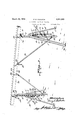
- Figure l is a perspectiveview of the com ⁇ i plete trestle, embodying ⁇ my improvements, setup and ready for use, -fulllines representing the positions of the elevating levers -when ready for use, and dotted lines show- ⁇ ing the levers in their suspended positions,
- Fig. 2 is af detail, vertical-section through one 'of the trestles, full lines fshowingthe positions of the upright, brace, and lever prior to'elevation of the upright and brace,
- the standardsy or frames l which are of angle steel construction, have cross braces 2,-
- the angle steel vertically fadjustable'uprights 3 are provided with the vertically arranged series of'elongated slots 4. as in the construction of my ⁇ application Serial No.' 198.846. These slots. instead of being utilized for the reception of hooks as in my aforesaid application ⁇ are adapted toreceive improved ⁇ automatically-acting pawls 5 which, by their engagement with the margins ofthe slots. are automatically released when the uprights 3 are elevated. only to engage the margin of a succeeding slot to again lock the upright in v its elevated position. Y
- the upriglits 3 ⁇ are slidably ⁇ mounted in guides 6, 6', such guides being preferably of malleable iron and of one-piece construction and they are riveted or welded to the crosspieces 2, 2, respectively.
- a J-shaped hook clamp 7 whose i shank is slidable laterally through the holder i J-shaped hook clamp ,7, which engages the outstanding web of the upright 3, clamps the' upright against the crosspiece 2.
- rlhe holder v 8 maybe secured to the crosspiece 2 byy rivets or other fastenings 9.
- the pawls 5 are provided with lpivots 10 which are carried by the earsv 13', the latter being riveted to the crosspiece 2.
- Eachpawl is provided with an enlarged head 5 and a tail 5", the weight of the head causing the pawl normally to fall forwardly toward thevupright 3 so that it will be adapted to enter the nearestslot 4 which is presented to it.
- the active' face of the pawl is inclineded or beveled, as'shown at 5- to serve as a cam surface adapted to be engaged by the lower margin of the slot 4 'when the upright 3 is elevated, whereby the pawl is pushed back to thefdotted line position, Eig.
- the tail 5 enables the pawl to be' heid by hand in thedotted line position when it is desired to lower the upright.
- One of the astenings 9" may be in the form of a suspended hook 11 having a screW ⁇ threaded shank passing through the crosspiece 2. and provided with a nut vso that any desired vertical adjustment of the hook'may be obtained. If preferred, the hook 11 may be entirely independent' of the fastenings 9.
- the hook 11 serves as a suspendingmeans for the fulcrum for the improved operating lever 12.
- the levers 12 rare provided with hooked or notched ends 15 which are adapted to enter engage the upper margin thereof.
- hook clamps comprise clamps- 16 which have screw threaded Shanks lslidable through lugs or loops 17 riveted or welded to the upper parts of the uprights3 and the screw threaded shanks are provided with handled nuts 18 for drawing thevhooked ends 19 into penetrating engagement with the wooden trestle, plank, timber or connecting piece 20.
- Angle steel braces 21 which are pivoted to the uprights 3 at 22 and carry hook clamps 23 at their upper ends, are of the same construction and arranged and adapted to c0- operate with the wooden plankor timber as described in my application Serial No. 198,846, That is to say, one web of each of the angle steel braces 21 lies flatwise against.y
- the clamps 7 are loosened by turning the handled nuts 9 backwardly.
- the lever or levers 12 vare then operated in insert their hooked ends 15 in the slots 4, insuccession, and the lever or leversare depressed at their outer ends to cause the uprights 3 t o-be elevated to they desired extent.
- the pawl or pawls 5 are cammed to the dotted line position only toffall back into the n eXt slot 4 to support the upright3 until the operator can hook the lever 12 into anlf other slot and can depress the lever to elevate the upright again.
- the pawls 5 support the uprights and the timber until the clamps 9 can be tightened, The pawls continue to remain in engagement with the slots 4 and to assist in supporting the ⁇ uprights.
- the lever or levers l2 are removed from the slots 4 and then hang down freely, or, they may be entirely removed from the trestle, if desired.
- the clamps 7 are released, the tails 5 ofthe pawls are held by hand, the lever or levers l2 having been engaged with a slot 4, the upright oruprights may be gradually lowered until the trestle is at the proper height, whereupon the pawl or pawls may again be allowed to engage one of the slots to hold the trestle in its lowered position.
- lVhat l claim is l. ln an adjustable elevating trestle, the combination with a supporting frame, of an angle steel vertically adjustable upright Carried by said frame and provided with a vertically arranged series of slots, an automatically locking, manually releasable pawl carried by the frame which is adapted to enter the slots to sustain the upright in the position to which it is adjusted, said pawl being arranged to be automatically released by the action of the margins of said slots when the upright is being elevated, and a manually operable lever suspended from the frame and independent of said pawl, said lever being adapted for cri-operation with the slots to raise and lower the upright.
- an adjustable elevating trestle the combinatie-n with a supporting frame, of an angle steel vertically adjustable upright carried by said frame and provided with a vertically arranged series of slots, an automatically leclring, manually releasable pawl car.- ried by the frame which is adapted te enter the slots to sustain the upright in the pesi,- tion to which adjusted, said pawl being arranged to automatically released by the action of the margins of said slots when the upright is being elevated, a manually operable lever, independent of said pawl, a suspending fulcruni member including a linkage and a hoolr by which said lever is suspended from said frame, said lever being adapted for detachable insertion in the aforesaid slots independently of the engagement of the slots by the pawl so that it may be used to shift the upright or to be disengaged freni the upright and suspended from its fulcrum.
- an adjustable elevating trestle the combination with a supporting frame, of an angle steel vertically adjustable upright ried by said frame and provided with a vertically arranged series of slots in ene of its webs, an automatically locking manually reit is released by the action-'of the margins of said slots whenthe upright is being elevated, a'
- an automatically lock-v ing, manually releasable pawl carried.r by the frame whichis adapted to engage lthe slots and sustain the upright in positions to which said upright may be elevated, said pawl being adapted to ratchet on .the margins ofthe slots of the upright when the latter is being elevated, a clamp carried by the upright c adapted for engaging a piece of timber to be ⁇ sol supported, an angle steel brace pivoted to the upright andadapted to be raised andflowered therewith, a clamp carried 4by said brace.
- a clamp carried by the frame independ-v ent of the pawl for fastening the uprightto the frame and an operating lever suspended from the frame and which is independent of:
- an adjustable elevating trestle the 1 vcombination with a supportingfra-me or standard-of a vertically adjustable upright of angle steel having a web thereof provided with means at different points of its length adapted for use when elevating and locking said upright, an automatically locking and manually releasable pawl adapted for automatic engagement with the aforesaid means to sustain the upright, or for automatic release from said means when the upright is elevated, an elevating manually operable lever ⁇ suspended from the frame for releasable engagement with the aforesaid means on the upright whereby the upright may be elevated or ,lowered by manipulating the lever when engaged with said upright, and a clamp forl fasten ing the upright to the frame after said upright has been elevated or lowered, thereby to supplement the sustaining action of the pawl on the upright.
- an adjustable elevating trestle the combination with a supporting frame having an upper laterally-arranged part, and a 1ow-y er laterally-arranged part, of an upright adapted for elevation and lowering onv said frame, A automatically-acting, manually re.
Landscapes
- Engineering & Computer Science (AREA)
- Architecture (AREA)
- Mechanical Engineering (AREA)
- Civil Engineering (AREA)
- Structural Engineering (AREA)
- Conveying And Assembling Of Building Elements In Situ (AREA)
Description
March 29, 1932. P, E GOODWW 1,851,668
This invention relates to improvements on Vthe adjustable trestle disclosed in my pending application Serial No. 198,846. y
Y In an adjustable trestle such as disclosed and claimed in my aforesaid application, 1t is necessary for the workman or artisan who is setting up and adjusting the trestle, to manually lift the vertical angle `steel adjustable uprights and when thisis done with the piece of timber in position, considerable ef.- fort and strength are required.
The object ofA the present invention is to provide improvements on the adjustable trestle disclosed in the aforesaid application, whereby each upright may be easily and quickly elevated to theV desired extent and, also, means for automatically locking the uprights in the position to which they are elevated, thus relieving the workman or artisan from the necessity of exerting strength to support these uprights until they are clamped to the standards or frames which carry them.
My improvements embody the openings or` slots arranged in a vertical series in one web of each of the angle steel uprights; special, automatically-locking andV releasing pawls' carried 'by the standards and cofoperating with the margins of the aforesaid slots, ful- Y cruming means, preferably links or chains, carried by thestandards, and a lever or levers of special construction suspended by said fulcruming means and having their effective ends adapted to enter the slots so that, when said levers are manually operated, the uprights may be elevated with small eiiort, or, may be readily released from the automatic pawls and lowered to any desired extent.
Each of the standards or frames may have its own lever, or, only one lever and fulcruming means may be used and arranged to be transferred from one standard to the other, in which event the lever is detachably sus pended from the standard so that it may be used with either standard.
The automatically locking and releasing pawls hold the uprights in position to which they are elevated or lowered until the locking means for clamping theuprights to the standards are tightened to make the 'trestle ready for use, provided the angle steel braces lhave pawl being in full lines; and
1929. serial No. 381,298.
been clamped tothe piece vof -timberwhich is supported by the uprights; thus, the worln.
man or artisan adjusting the trestleneed eX-y ert only a very slight manual effort to set up the trestle to the height desired. j
In the accompanying drawings:
Figure l is a perspectiveview of the com` i plete trestle, embodying` my improvements, setup and ready for use, -fulllines representing the positions of the elevating levers -when ready for use, and dotted lines show-` ing the levers in their suspended positions,
Fig. 2 is af detail, vertical-section through one 'of the trestles, full lines fshowingthe positions of the upright, brace, and lever prior to'elevation of the upright and brace,
and dotted lines representing `the elevated position of the upright and the depressed Fig' is a'detail horizontal Y'section talien just above one ot the clamps. Y
The standardsy or frames l, which are of angle steel construction, have cross braces 2,-
2 oi angle steel construction rivetedv or welded thereto.
The angle steel vertically fadjustable'uprights 3 are provided with the vertically arranged series of'elongated slots 4. as in the construction of my `application Serial No.' 198.846. These slots. instead of being utilized for the reception of hooks as in my aforesaid application` are adapted toreceive improved` automatically-acting pawls 5 which, by their engagement with the margins ofthe slots. are automatically released when the uprights 3 are elevated. only to engage the margin of a succeeding slot to again lock the upright in v its elevated position. Y
` The upriglits 3` are slidably` mounted in guides 6, 6', such guides being preferably of malleable iron and of one-piece construction and they are riveted or welded to the crosspieces 2, 2, respectively.
To clamp the uprights in the position to ian which they are elevated or lowered, there is provided a J-shaped hook clamp 7 whose i shank is slidable laterally through the holder i J-shaped hook clamp ,7, which engages the outstanding web of the upright 3, clamps the' upright against the crosspiece 2. rlhe holder v 8 maybe secured to the crosspiece 2 byy rivets or other fastenings 9.
By utilizing the hook clamp 7, in addition to the pawl 5, on each standard 1, there is no possibility Yofy accidental release of the pawl 5 although it will be understood that the pawl supports the upright 3 and the weight carried thereby.
The pawls 5 are provided with lpivots 10 which are carried by the earsv 13', the latter being riveted to the crosspiece 2..
Eachpawlis provided with an enlarged head 5 and a tail 5", the weight of the head causing the pawl normally to fall forwardly toward thevupright 3 so that it will be adapted to enter the nearestslot 4 which is presented to it. The active' face of the pawl isinclined or beveled, as'shown at 5- to serve as a cam surface adapted to be engaged by the lower margin of the slot 4 'when the upright 3 is elevated, whereby the pawl is pushed back to thefdotted line position, Eig. 3, enabling the upright 3 to be elevated as lfar as desired inasmuch as the margins or successive slots presented to the pawl cause it to ratchet kback until, finally, the elevating action eX- erted on the vupright 3 ceases, whereupon the overweighted head 5 causes the pawl todrop into the nearest slot 4 and, thereupon, the
upper margin of theslot rests upon the top of the pawland the upright is supported by said pawl, as the head of the pawl then rests upon the crosspiece 2. 1
The tail 5 enables the pawl to be' heid by hand in thedotted line position when it is desired to lower the upright. One of the astenings 9"may be in the form of a suspended hook 11 having a screW` threaded shank passing through the crosspiece 2. and provided with a nut vso that any desired vertical adjustment of the hook'may be obtained. If preferred, the hook 11 may be entirely independent' of the fastenings 9.
The hook 11 serves as a suspendingmeans for the fulcrum for the improved operating lever 12.
A suspending orfulcruming chain or link vide one lever 12, as it may be alternately the i slotsr 4 and to able,rin which event, two levers maybe used,
which will hang freely after the uprights 3. have been suitably adjusted. Y
The levers 12rare provided with hooked or notched ends 15 which are adapted to enter engage the upper margin thereof.
The upper ends of the uprights are pro? be of substantially the' same construction andk adapted tooperate the same as shown 'and' described in my application Serial No. 198,846. f These hook clamps comprise clamps- 16 which have screw threaded Shanks lslidable through lugs or loops 17 riveted or welded to the upper parts of the uprights3 and the screw threaded shanks are provided with handled nuts 18 for drawing thevhooked ends 19 into penetrating engagement with the wooden trestle, plank, timber or connecting piece 20.
a side of the plank or timber 20, one of the braces lying against one side of the plank or timber 20 and the other brace lying against the opposite side thereof. The penetrating hooks 24 of the respective hook clamps 23 engage opposite sides' of the plankl or timber 20 and are drawn into penetrating engagement therewith by tightening the handled nuts which are carried by the screw threaded shanks ot said hook clamps V23.
As with the construction set up in my aforesaid application, so in the present trestle, great strength and rigidity are obtained, due to the angle steel construction of the standards 1, crosspieces 2, 2, uprights '3, and braces 21.y
When it is desired to elevate the uprights 3 or to set up the trestle to any desiredheight,
the clamps 7 are loosened by turning the handled nuts 9 backwardly. The lever or levers 12 vare then operated in insert their hooked ends 15 in the slots 4, insuccession, and the lever or leversare depressed at their outer ends to cause the uprights 3 t o-be elevated to they desired extent. During this operation, the pawl or pawls 5 are cammed to the dotted line position only toffall back into the n eXt slot 4 to support the upright3 until the operator can hook the lever 12 into anlf other slot and can depress the lever to elevate the upright again. Finally, when both uprights 3 have been raised to the desired height, the pawls 5 support the uprights and the timber until the clamps 9 can be tightened, The pawls continue to remain in engagement with the slots 4 and to assist in supporting the` uprights. After the trestle has been suitably adjusted, the lever or levers l2 are removed from the slots 4 and then hang down freely, or, they may be entirely removed from the trestle, if desired.
`When it is desired to lower the uprights, the clamps 7 are released, the tails 5 ofthe pawls are held by hand, the lever or levers l2 having been engaged with a slot 4, the upright oruprights may be gradually lowered until the trestle is at the proper height, whereupon the pawl or pawls may again be allowed to engage one of the slots to hold the trestle in its lowered position.
lVhat l claim is l. ln an adjustable elevating trestle, the combination with a supporting frame, of an angle steel vertically adjustable upright Carried by said frame and provided with a vertically arranged series of slots, an automatically locking, manually releasable pawl carried by the frame which is adapted to enter the slots to sustain the upright in the position to which it is adjusted, said pawl being arranged to be automatically released by the action of the margins of said slots when the upright is being elevated, and a manually operable lever suspended from the frame and independent of said pawl, said lever being adapted for cri-operation with the slots to raise and lower the upright.
2. In an adjustable elevating trestle, the combinatie-n with a supporting frame, of an angle steel vertically adjustable upright carried by said frame and provided with a vertically arranged series of slots, an automatically leclring, manually releasable pawl car.- ried by the frame which is adapted te enter the slots to sustain the upright in the pesi,- tion to which adjusted, said pawl being arranged to automatically released by the action of the margins of said slots when the upright is being elevated, a manually operable lever, independent of said pawl, a suspending fulcruni member including a linkage and a hoolr by which said lever is suspended from said frame, said lever being adapted for detachable insertion in the aforesaid slots independently of the engagement of the slots by the pawl so that it may be used to shift the upright or to be disengaged freni the upright and suspended from its fulcrum.
3. ln an adjustable elevating trestle, the combination with a supporting frame, of an angle steel vertically adjustable upright ried by said frame and provided with a vertically arranged series of slots in ene of its webs, an automatically locking manually reit is released by the action-'of the margins of said slots whenthe upright is being elevated, a'
manually operable lever suspended from the frame andwhich. is independent of the pawl and which is adapted for co-operation with the slots te raise and lower the upright, and a hook-clamp carried by the supporting frame, Y, said clamp being engageab'le with the other Y web of the angle steel upright and adapted tov dra-w the upright against the frame after the upright has been raised or lowered, thereby` to supplement the retaining action of the pawl on the upright. g 4. In an adjustable trestle, the combination with a supporting frame, of an angle steel `vertically adjustable upright carried thereby and provided with a vertically ar-. ranged series of slots, an automatically lock-v ing, manually releasable pawl carried.r by the frame whichis adapted to engage lthe slots and sustain the upright in positions to which said upright may be elevated, said pawl being adapted to ratchet on .the margins ofthe slots of the upright when the latter is being elevated, a clamp carried by the upright c adapted for engaging a piece of timber to be` sol supported, an angle steel brace pivoted to the upright andadapted to be raised andflowered therewith, a clamp carried 4by said brace. adapted to engage the piece of timber aforesaid, a clamp carried by the frame independ-v ent of the pawl for fastening the uprightto the frame, and an operating lever suspended from the frame and which is independent of:
the pawl and thevclamp, said lever being adapted for engaging the upright for the purpose ofelevating and lowering the upright and brace.
5. lIn an adjustable elevating trestle, the 1 vcombination with a supportingfra-me or standard-of a vertically adjustable upright of angle steel having a web thereof provided with means at different points of its length adapted for use when elevating and locking said upright, an automatically locking and manually releasable pawl adapted for automatic engagement with the aforesaid means to sustain the upright, or for automatic release from said means when the upright is elevated, an elevating manually operable lever` suspended from the frame for releasable engagement with the aforesaid means on the upright whereby the upright may be elevated or ,lowered by manipulating the lever when engaged with said upright, and a clamp forl fasten ing the upright to the frame after said upright has been elevated or lowered, thereby to supplement the sustaining action of the pawl on the upright. j
6. In an adjustable elevating trestle, the combination with a supporting frame having an upper laterally-arranged part, and a 1ow-y er laterally-arranged part, of an upright adapted for elevation and lowering onv said frame, A automatically-acting, manually re.
leasable paWl-,means onthe lower laterally-l arranged part of the frame, ratchet-means on the'upright adapted for engagement with the pawlmeans for 'holding thergupright in the position to which it is adjusted, suspending means Vcarried by the upper laterally-arranged part of the frame, an operating lever Vindependent of the pawl-means which is adapted to be engaged with the aforesaid ratchetemeans for raising and lowering the upright, anda fulorum member for said lever depending from the suspending means, whereby the lever is suspended from the suspending means.
7. In an adjustable elevating trestle, the
combination with a supporting frame having an upper laterally-arranged part, and a lower laterally-arranged part, of an upright vadapted for elevation and lowering on saidk frame5- automatically-acting, manually releasable pawl-means on the lower laterallyarranged part of the frame, ratchet-means on the upright adapted for. engagement with the pa'wlfmeans for holding the upright4 in the position to which it is adjusted, suspending Vmeans carried by the upper laterally-arranged part of the frame, an operating lever independent of the pawl-meansy which is adapted to beengaged with the aforesaid f ratchet-means for raising and lowering the upright, a fulorum member for said lever depending from the suspending means, whereby the'lever is suspended from the suspending means, and a clamp carried by the upper laterally-'arranged part of the frame and Vindependent of the pawl-means. and ratchetT Y means and lever, said clamp being adapted to fasten theuprightto the frame to supplement the sustaining action ofthe paWl-means on the upright. n
In testimony whereof I aflix my signature.
PERoY E; Go'oDwrN.
Priority Applications (1)
| Application Number | Priority Date | Filing Date | Title |
|---|---|---|---|
| US381298A US1851668A (en) | 1929-07-26 | 1929-07-26 | Adjustable elevating trestle |
Applications Claiming Priority (1)
| Application Number | Priority Date | Filing Date | Title |
|---|---|---|---|
| US381298A US1851668A (en) | 1929-07-26 | 1929-07-26 | Adjustable elevating trestle |
Publications (1)
| Publication Number | Publication Date |
|---|---|
| US1851668A true US1851668A (en) | 1932-03-29 |
Family
ID=23504492
Family Applications (1)
| Application Number | Title | Priority Date | Filing Date |
|---|---|---|---|
| US381298A Expired - Lifetime US1851668A (en) | 1929-07-26 | 1929-07-26 | Adjustable elevating trestle |
Country Status (1)
| Country | Link |
|---|---|
| US (1) | US1851668A (en) |
Cited By (4)
| Publication number | Priority date | Publication date | Assignee | Title |
|---|---|---|---|---|
| US4947962A (en) * | 1989-08-21 | 1990-08-14 | Helsper Steve M | Adjustable scaffold support |
| US5954156A (en) * | 1998-08-17 | 1999-09-21 | Cooke; John E. | Adjustable saw horse |
| US20080236945A1 (en) * | 2007-04-02 | 2008-10-02 | Larouche Jean-Guy | Adjustable-height sawhorse |
| GB2543081A (en) * | 2015-10-08 | 2017-04-12 | Gerard Mccoy James | A work bench assembly |
-
1929
- 1929-07-26 US US381298A patent/US1851668A/en not_active Expired - Lifetime
Cited By (5)
| Publication number | Priority date | Publication date | Assignee | Title |
|---|---|---|---|---|
| US4947962A (en) * | 1989-08-21 | 1990-08-14 | Helsper Steve M | Adjustable scaffold support |
| US5954156A (en) * | 1998-08-17 | 1999-09-21 | Cooke; John E. | Adjustable saw horse |
| US20080236945A1 (en) * | 2007-04-02 | 2008-10-02 | Larouche Jean-Guy | Adjustable-height sawhorse |
| GB2543081A (en) * | 2015-10-08 | 2017-04-12 | Gerard Mccoy James | A work bench assembly |
| GB2543081B (en) * | 2015-10-08 | 2021-12-01 | Gerard Mccoy James | A work bench assembly |
Similar Documents
| Publication | Publication Date | Title |
|---|---|---|
| US3288249A (en) | Gutter bridging ladder attachment | |
| US8025126B1 (en) | Roof bracket | |
| US11761217B2 (en) | Scaffold gate toeboard assembly for use on a scaffold gate | |
| US2814533A (en) | Shingling scaffold | |
| US1851668A (en) | Adjustable elevating trestle | |
| US2049893A (en) | Support for scaffolds or the like | |
| US1890029A (en) | Scaffold | |
| US7258197B1 (en) | Scaffold bracket | |
| US2035537A (en) | Truck platform ladder | |
| US2891819A (en) | Scaffolding jack | |
| US1478823A (en) | Roof-projection ladder support | |
| US1015123A (en) | Ladder. | |
| US328999A (en) | heney ballmann | |
| US1398471A (en) | Collapsible bench-leg | |
| US1416296A (en) | Scaffold machine | |
| US2212384A (en) | Hoisting attachment for ladders | |
| US2896830A (en) | Combined step and stairway and extension ladder | |
| US2761743A (en) | Adjustable scaffold leg unit | |
| US1879376A (en) | Scaffold | |
| US2414078A (en) | Scaffolding | |
| US1935896A (en) | Portable or adjustable trestle | |
| US1895766A (en) | Method of and means for attaching the uprights and members of scaffolding and other structures | |
| US2299823A (en) | Adjustable scaffolding | |
| US2980384A (en) | Scaffold hanger | |
| US2161239A (en) | Support for scaffolds |