US1851663A - Bail-like element and method of making - Google Patents
Bail-like element and method of making Download PDFInfo
- Publication number
- US1851663A US1851663A US493852A US49385230A US1851663A US 1851663 A US1851663 A US 1851663A US 493852 A US493852 A US 493852A US 49385230 A US49385230 A US 49385230A US 1851663 A US1851663 A US 1851663A
- Authority
- US
- United States
- Prior art keywords
- bail
- bails
- free ends
- making
- seats
- Prior art date
- Legal status (The legal status is an assumption and is not a legal conclusion. Google has not performed a legal analysis and makes no representation as to the accuracy of the status listed.)
- Expired - Lifetime
Links
- 238000004519 manufacturing process Methods 0.000 title description 8
- 239000011324 bead Substances 0.000 description 2
- 240000008801 Reseda odorata Species 0.000 description 1
- 238000005452 bending Methods 0.000 description 1
- 238000012856 packing Methods 0.000 description 1
- 238000007747 plating Methods 0.000 description 1
Images
Classifications
-
- B—PERFORMING OPERATIONS; TRANSPORTING
- B65—CONVEYING; PACKING; STORING; HANDLING THIN OR FILAMENTARY MATERIAL
- B65D—CONTAINERS FOR STORAGE OR TRANSPORT OF ARTICLES OR MATERIALS, e.g. BAGS, BARRELS, BOTTLES, BOXES, CANS, CARTONS, CRATES, DRUMS, JARS, TANKS, HOPPERS, FORWARDING CONTAINERS; ACCESSORIES, CLOSURES, OR FITTINGS THEREFOR; PACKAGING ELEMENTS; PACKAGES
- B65D1/00—Rigid or semi-rigid containers having bodies formed in one piece, e.g. by casting metallic material, by moulding plastics, by blowing vitreous material, by throwing ceramic material, by moulding pulped fibrous material or by deep-drawing operations performed on sheet material
- B65D1/02—Bottles or similar containers with necks or like restricted apertures, designed for pouring contents
- B65D1/0223—Bottles or similar containers with necks or like restricted apertures, designed for pouring contents characterised by shape
- B65D1/023—Neck construction
- B65D1/0253—Means facilitating removal of the closure, e.g. cams, levers
Definitions
- the present invention relates to bail-like elements of the type, for example, disclosed in my United States Patent 1,777,077 issued September 80, 1930.
- the bail-like element has the major function of opener, although it may also be used as a bail and has the form of such an element.
- the present invention relates particularly to an improvement in this bail and may be conveniently, described in comparison therewith.
- the bail of the patent is adapted for attachment to bottles, jars and the like, the free ends of the the bail being designed to grip spaced seats formed in the articleto be associated therewith.
- the free ends of the bail being designed to grip spaced seats formed in the articleto be associated therewith.
- they have been formed with their free ends considerably spaced apart, it having been thought only necessary to close them sulficiently to give tension when spread slightly and engaged in their seats.
- the bails are ordinarily manufactured at a point remote from the point of assembly with the containers-and have been transported from the one point to the other loose in packing cases or similar receptacles. Due to the spaced relation of the free ends of the respective bails, it has been found that in thus commingling and handling them they become badly intertangled and each must be separately untangled from the mass with a consequent great loss in time and labor. The same difiiculty arises, as may be imagined, if the bails are placed in a tumbling machine for plating.
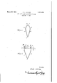
- t Figure 1 is a plan view of abail asinitially formed
- i Figure 2 is a-iplan' view of the bail asfattached to a jar, the latter being shown: only. in part.. x i J
- the bail as shown is substantially V-shaped and comprises legs 5 and 6 joined together at anapex7. Adja; cent their free ends, the legs 5land 6 are bent inwardly to form the obtuse angles indicated at 8 and9, while at their eXtremitiesthe-legs. are bent inwardly at substantially right angles to their adjacent portions to form the opposed lugs 10 and 11.
- the bail, as described, is formed from a blank in the form of a strip, ordinarily of wire.
- the apex angle is closed to a greater extent than heretofore, so as to bring the end portions 10 and lltogether.
- These end portions may be in actual contact or they may be slightly overlapped, but in any event, assuming the element tobe made ofwire, the distance between the end portions 10 and 11 must at least be less than the diameter of the wire.
- bent end portions 10 and 11 Due to the form of the bent end portions 10 and 11 they may be brought together with legs 5 and 6 still in spaced relation, so as to be readily gripped when the element is to be applied to an article as shown in Figure 2. Further, it will be noted that end portions or lugs l0and 11 come together to form an outer obtuse angle, so that there is very little danger of another element being wedged between and past them.
- reference numeral 12 designates the top bead of a jar 13, the bead having formed therein seats 14 and 15, as described in my patent above referred to.
- the seats are considerably spaced apart, so that when the bail is spread from its initial closed position, considerable gripping tension will be developed and its ends will thus be securely seated.
- a deformable substantially V-shaped bail-like element having opposed inwardly bent portions remote from its apex and being so formed in manufacture thatsaid inwardly bent portions assume a position in contact with each other, whereby to prevent intertangling of the elements when commingled.
- a deformable substantially V-shaped bail-like element of wire said element having opposed inwardly bent portions at its free ends and being so formed in manufacture that said inwardly bent free ends assume a position in contact with each other, whereby to prevent intertangling of the. elements when commingled.
- a de- Y .formable bail-like element having opposed inwardly bent free ends and being so formed in manufacturethat said ends assume a position in contactwith each other whereby to prevent intertangling with other similar elements when commingled therewith.
Landscapes
- Engineering & Computer Science (AREA)
- Ceramic Engineering (AREA)
- Mechanical Engineering (AREA)
- Preliminary Treatment Of Fibers (AREA)
Description
March 1932- F. L. DARLING v BAIL LIKE ELEMENT AND METHCD OF MAKING Filed Nov. 6, '1950 gwumtom 30/76 Z. Bar/f0 Patented Mar. 29, 1932 UNITED STATE$ COMPANY, INC., 013 BALTIMORE, MARY Lenin A coEr-o ArIo Yo NEW YORK, ,1
BAIL-LIKE ELEMENT AND METHOD OF MAKING Application filed November The present invention relates to bail-like elements of the type, for example, disclosed in my United States Patent 1,777,077 issued September 80, 1930. According to the disclosure of said patent, the bail-like element has the major function of opener, although it may also be used as a bail and has the form of such an element. The present invention relates particularly to an improvement in this bail and may be conveniently, described in comparison therewith.
The bail of the patent is adapted for attachment to bottles, jars and the like, the free ends of the the bail being designed to grip spaced seats formed in the articleto be associated therewith. In the manufacture of the bails, they have been formed with their free ends considerably spaced apart, it having been thought only necessary to close them sulficiently to give tension when spread slightly and engaged in their seats.
The bails are ordinarily manufactured at a point remote from the point of assembly with the containers-and have been transported from the one point to the other loose in packing cases or similar receptacles. Due to the spaced relation of the free ends of the respective bails, it has been found that in thus commingling and handling them they become badly intertangled and each must be separately untangled from the mass with a consequent great loss in time and labor. The same difiiculty arises, as may be imagined, if the bails are placed in a tumbling machine for plating.
Now, I have found that if informing the bails their free ends are brought together, so that the bails are in substantially the form of closed loops, they may be commingled and transported or otherwise handled with? out the occurrence of any intertangling. The bails are deformable, so that they retain any form to which they may be bent, but at the same time they have a certain inherent resiliency which causes them to grip firmly in the seats provided for them. Byspreading the free ends of the bails from closed relation to the spaced relation necessary to engage them with the seats a greater gripping tenthem a degree of gripping 6,1930. Serial No. 493,852. 4
sion issecured than when th e endsaremerely spread from an initially spaced: relationra's was-done heretofore. k A
Thus, by initially bringing theendsof'the:
bails together, as contemplated under the present invention, intertangling of the bails is effectively prevented and greater. gripping tension is secured whenthe bails are applied totheir associat-edarticles. 1 i
A bail similar to that shown inmy above mentioned patent, but formed in. accordance with and typical of the presentinvention, is shown in theaccompanying drawings. In the drawings: F v
t Figure 1 is a plan view of abail asinitially formed, and i Figure 2 is a-iplan' view of the bail asfattached to a jar, the latter being shown: only. in part.. x i J Referring to the drawings the bail as shown is substantially V-shaped and comprises legs 5 and 6 joined together at anapex7. Adja; cent their free ends, the legs 5land 6 are bent inwardly to form the obtuse angles indicated at 8 and9, while at their eXtremitiesthe-legs. are bent inwardly at substantially right angles to their adjacent portions to form the opposed lugs 10 and 11. The bail, as described, is formed from a blank in the form of a strip, ordinarily of wire. In bending the blank to the form shown the apex angle is closed to a greater extent than heretofore, so as to bring the end portions 10 and lltogether. These end portions may be in actual contact or they may be slightly overlapped, but in any event, assuming the element tobe made ofwire, the distance between the end portions 10 and 11 must at least be less than the diameter of the wire. a
Due to the form of the bent end portions 10 and 11 they may be brought together with legs 5 and 6 still in spaced relation, so as to be readily gripped when the element is to be applied to an article as shown in Figure 2. Further, it will be noted that end portions or lugs l0and 11 come together to form an outer obtuse angle, so that there is very little danger of another element being wedged between and past them.
In Figure 2, reference numeral 12 designates the top bead of a jar 13, the bead having formed therein seats 14 and 15, as described in my patent above referred to. The seats are considerably spaced apart, so that when the bail is spread from its initial closed position, considerable gripping tension will be developed and its ends will thus be securely seated. I
Although 'I have shown and described a specific and preferred embodiment of my invention, it will be understood that I do not limit myself except as determined in the following claims. I
I claim: I
1. As a new article of manufacture, a deformable substantially V-shaped bail-like element having opposed inwardly bent portions remote from its apex and being so formed in manufacture thatsaid inwardly bent portions assume a position in contact with each other, whereby to prevent intertangling of the elements when commingled.
' 2. As a new article of manufacture, a deformable substantially V-shaped bail-like element of wire, said element having opposed inwardly bent portions at its free ends and being so formed in manufacture that said inwardly bent free ends assume a position in contact with each other, whereby to prevent intertangling of the. elements when commingled.
3. As a new article of manufacture, a de- Y .formable bail-like element having opposed inwardly bent free ends and being so formed in manufacturethat said ends assume a position in contactwith each other whereby to prevent intertangling with other similar elements when commingled therewith.
In testimony whereof I have hereunto set" my hand. 0 v
FRANK LEE DARLING.
Priority Applications (1)
| Application Number | Priority Date | Filing Date | Title |
|---|---|---|---|
| US493852A US1851663A (en) | 1930-11-06 | 1930-11-06 | Bail-like element and method of making |
Applications Claiming Priority (1)
| Application Number | Priority Date | Filing Date | Title |
|---|---|---|---|
| US493852A US1851663A (en) | 1930-11-06 | 1930-11-06 | Bail-like element and method of making |
Publications (1)
| Publication Number | Publication Date |
|---|---|
| US1851663A true US1851663A (en) | 1932-03-29 |
Family
ID=23961960
Family Applications (1)
| Application Number | Title | Priority Date | Filing Date |
|---|---|---|---|
| US493852A Expired - Lifetime US1851663A (en) | 1930-11-06 | 1930-11-06 | Bail-like element and method of making |
Country Status (1)
| Country | Link |
|---|---|
| US (1) | US1851663A (en) |
-
1930
- 1930-11-06 US US493852A patent/US1851663A/en not_active Expired - Lifetime
Similar Documents
| Publication | Publication Date | Title |
|---|---|---|
| US1548459A (en) | Metal cap | |
| US2760262A (en) | Method of making a bail band | |
| US1851663A (en) | Bail-like element and method of making | |
| US2268339A (en) | Strap joint | |
| US646091A (en) | Rope-thimble. | |
| US2343571A (en) | Bag closure | |
| US2297771A (en) | Box fastener | |
| US2277108A (en) | Method of attaching opener keys to end closures of tear strip cans | |
| US1709556A (en) | Guy-strand guard | |
| US2112670A (en) | Side seam for can bodies | |
| US2205135A (en) | Clamping ring for containers | |
| US2848267A (en) | Stud lift adapter | |
| US1165131A (en) | Bottle-cap. | |
| US982875A (en) | Bottle-seal. | |
| US1677253A (en) | Friction cap for bottles and jars | |
| US1753313A (en) | Noninterlinking nut-lock washer | |
| US822895A (en) | Closure for bottles, jars, &c. | |
| US1976088A (en) | Sausage mold | |
| US1739755A (en) | Method of and means for sealing articles with wire | |
| US2845174A (en) | Coupling device for containers | |
| US1426304A (en) | Crate for milk bottles | |
| US1625210A (en) | Jar handle and method of producing same | |
| US1781611A (en) | Basket handle | |
| US648060A (en) | Clamp for holding fruit-jars. | |
| US1695301A (en) | Bottle closure |