US1851654A - Shock absorber - Google Patents
Shock absorber Download PDFInfo
- Publication number
- US1851654A US1851654A US466202A US46620230A US1851654A US 1851654 A US1851654 A US 1851654A US 466202 A US466202 A US 466202A US 46620230 A US46620230 A US 46620230A US 1851654 A US1851654 A US 1851654A
- Authority
- US
- United States
- Prior art keywords
- shaft
- drum
- shoes
- shoe
- engaging
- Prior art date
- Legal status (The legal status is an assumption and is not a legal conclusion. Google has not performed a legal analysis and makes no representation as to the accuracy of the status listed.)
- Expired - Lifetime
Links
- 239000006096 absorbing agent Substances 0.000 title description 11
- 230000035939 shock Effects 0.000 title description 10
- 239000011435 rock Substances 0.000 description 14
- 230000006835 compression Effects 0.000 description 7
- 238000007906 compression Methods 0.000 description 7
- 238000010276 construction Methods 0.000 description 7
- 230000033001 locomotion Effects 0.000 description 7
- 230000000694 effects Effects 0.000 description 5
- 239000000314 lubricant Substances 0.000 description 4
- 239000002184 metal Substances 0.000 description 3
- 230000010355 oscillation Effects 0.000 description 3
- 230000003534 oscillatory effect Effects 0.000 description 2
- 230000002093 peripheral effect Effects 0.000 description 2
- 238000004519 manufacturing process Methods 0.000 description 1
- 230000003014 reinforcing effect Effects 0.000 description 1
Images

Classifications
-
- F—MECHANICAL ENGINEERING; LIGHTING; HEATING; WEAPONS; BLASTING
- F16—ENGINEERING ELEMENTS AND UNITS; GENERAL MEASURES FOR PRODUCING AND MAINTAINING EFFECTIVE FUNCTIONING OF MACHINES OR INSTALLATIONS; THERMAL INSULATION IN GENERAL
- F16F—SPRINGS; SHOCK-ABSORBERS; MEANS FOR DAMPING VIBRATION
- F16F7/00—Vibration-dampers; Shock-absorbers
- F16F7/02—Vibration-dampers; Shock-absorbers with relatively-rotatable friction surfaces that are pressed together
- F16F7/06—Vibration-dampers; Shock-absorbers with relatively-rotatable friction surfaces that are pressed together in a direction perpendicular or inclined to the axis of rotation
Definitions
- the invention relates to shock absorbers and has for its object the obtaining of a construction which will frictionally resistboth the compression and rebound movements of the vehicle spring but to a variable degree and with a greater resistance to the rebound than to the original compression. Further objects of the invention are to increase the resisting force with increase in amplitude of oscillation; to obtain a self-energizing construction; to provide for adjustment in the initial seating of the device and finally to obtain a simple and inexpensive construction from a manufacturing standpoint. With 5 these objects in view the invention consists in the construction as hereinafter set forth.
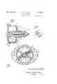
- Figure 1 is a plan view
- Figure 2 is a vertical central section on line go 22 of Figure 1;
- Figure 3 is a longitudinal section on line 33 of Figure 2;
- Figure 4 is an elevation of one of the friction shoes
- Figure 5 is a view similar to Figure 2 showing a modified construction and Figure 6 is a perspective view of one of the wedge shoes.
- my improvement comprises a housing including a cylindrical drum, an oscillatory shaft arranged concentric therewith and extending outward through a journal bearing, a rock arm for oscillating said shaft and friction shoes'for engaging as the inner surface of the drum which are actu ated by the oscillatory shaft and which resist the movement thereof.
- a housing including a cylindrical drum, an oscillatory shaft arranged concentric therewith and extending outward through a journal bearing, a rock arm for oscillating said shaft and friction shoes'for engaging as the inner surface of the drum which are actu ated by the oscillatory shaft and which resist the movement thereof.
- a. plate adapted to be attached to any suitable point on the vehicle frame and which is 40 formed with a circular recess B therein and a journal bearing C concentric with this recess.
- D is a cup shaped housing member having a cylindrical portion E which fits within the circular recess B, said housing being also providedwith a hub portion F for supporting a bushing G.
- H is a shaft having a portion H engaging the bearing C, a portion H for engaging the bushing G, and an intermediate portion H carrying a rock arm I preferably formed integral therewith.
- This rock arm extends diametrically of the cylindrical housing E and forms an actuating member for a pair of brake shoes J and J.
- These shoes are preferably formed of pressed sheet metal with segmental peripheral portions J fitting within the drum E and inturned flanges J 3 at the opposite sides thereof which are of greatest depth in the center and taper therefrom towards the opposite ends.
- At one point in the length of the shoe is an aperture K in the peripherythereof having inturned flanges K on opposite sides for engaging an end of the rock arm I.
- Each of the shoes is pressed against the inner face of the drum by a spring L which as shown in 65 Figure 2-is seated at its inner end in a recess M in the portion H of the shaft and against a disk N within said recess.
- the outer end of the'spring engages a wedge shaped shoe 0 between the brake shoes J and J.
- This shoe is formed of sheet metal to have a central portion 0 bearing against the spring and the wedge shaped end portions O for engaging'the flanges J of the shoes J and J the arrangement being such that the pressure of the spring against the wedge shoe 0 tends to hold the brake shoes in frictional engagement with the drum.
- a rock arm P is attached to the outer '80 end of the shaft H and the device is suitably mounted on the vehicle as in the usual manner with the plate A and rock arm P attached, the one to the vehicle frame and other to the axle or unsprung part.
- Oil or other lubricant is preferably placed within the housing D as by means of removable plugs Q. Whenever there is a verticalroscillation of the sprung portion of the vehicle this will cause a rocking of the shaft H in the bearings C .0 and G and through the medium of the rock arm I this will tend to rotate the shoes J and and J within the drum. Such movement.
- the means for effecting this is the location of the bearings on the, shoesengaging the rock arm I nearer the forward end of the shoe in the direction of rotation under compression ofthe vehicle spring than to the opposite ends of the shoe fourth of the length of the shoeaway from which constitutesthe forward end in the reverse rotation; It is well understood that in its forward end in'the direction of move ment under compression ofthe vehicle spring. This will produce only a slight wrapping or self-energizing effect on the brake shoe so that the frictional'resistance depends largely upon the tension of the spring L.
- the central portion H of the shaft H is transversely bored in axial alignment with'the' springs L and a pair of balls R are placed in this aperture to bear against the disksN.
- the shaft H is axially bored from its outer end to receive a stem S which has a taperingor conical point S at its inner end and a thread-ed portion S at its outer end engaging a correspondingly threaded bearing in the bore. By screwing this stem in ward the conical portion S will spread the balls R, thereby moving the abutment disks as desirable as that shown in Figure 2 as it.
- WVhat I claim as my invention is:
- a shock absorber the combination of a plate having a journal bearing therein and a surrounding annular recess, a housing having a cylindrical portion engaging said recess and a hub portion, a bushing 111 said hub portion, a shaft journalled in said bearing in said plate and said bushing, an arm on said shaft within said housing projecting diametrically of said housing, a pair of shoes frictionally engaging the inner face of the cylindrical portion of said housing and .provided with bearings for engaging said arm located at points nearer one end of each shoe than the other end thereof, and means for yieldably pressing said shoes infrictional engagement with said drum.
- a shock absorber the combination of a drum, a shaft journalled concentrically therein, friction shoes arranged within said drum with their ends spaced from each other, spring pressed wedge members between the ends of said shoes for forcing the same in frictional engagement with said drum, and
- a shock absorber the combination of a drum, a shaft journalled concentrically therein, a rock arm on said-shaft extending radially within said drum, a friction shoe engaging the inner face'of saiddrumahd havinga bearing for engaging said rock arm, a spring sea-ted within a recess in said shaft and bearingagainst said shoe to hold the same in frictional contact with the drum, and means operated from without the drum for adjusting the tension on said spring.
- a shock absorber the combination of a drum, a shaft journalled concentrically therein, a friction shoe within said drum, 2. rock arm on said shaft engaging said friction shoe to actuate the same, a stem extending inward through an axial passage in said shaft having a threaded engagement with said shaft at its outer end and provided with conical inner end portions, a spring for pressing said shoe in frictional engagement with said drum having its inner end engaging a transverse recess in said shaft which is in communication with said axial passage and an abutment for said spring bearing against the conical end ofsaid stem whereby an adjustment of said stem will alter the tension on said spring.
- a shock absorber comprising adrum, a
- a shock absorber the combination of a drum and a shaft journalled concentrically therein, of a friction shoe formed of pressed sheet metal having a segmental portion for engaging the inner face of the drum, and inwardly extending reinforcing flanges taper ing from the center towards the opposite ends, said shoe having a portion struck inward from its peripheral portion to form spaced bearings, and a rock arm on said shaft extending into engagement with said spaced bearings to actuate said shoe.
Landscapes
- Engineering & Computer Science (AREA)
- General Engineering & Computer Science (AREA)
- Mechanical Engineering (AREA)
- Braking Arrangements (AREA)
Description
March 29, 1932. T c. w. VAN RANST 1,851,654
v SHOCK ABSORBER Filed July 7, 1950 2 Shets-Sheet 1 INVENTOR Car/7625245 WE 79342256 4m 1% 1m a.
+ W ATTORNEw SHOCK ABSORBER Filed July 7, 1930 2 Sheets-Sheet 2 ATTORNEYS Patented Mar. 29, 1932 UNITED STATES CORNELIUS W. VAN RALNST, OF DETROIT, MICHIGAN v sHocx ABSORBER 7 Application filed July 7, 1930. Serial No. 466,202.
The invention relates to shock absorbers and has for its object the obtaining of a construction which will frictionally resistboth the compression and rebound movements of the vehicle spring but to a variable degree and with a greater resistance to the rebound than to the original compression. Further objects of the invention are to increase the resisting force with increase in amplitude of oscillation; to obtain a self-energizing construction; to provide for adjustment in the initial seating of the device and finally to obtain a simple and inexpensive construction from a manufacturing standpoint. With 5 these objects in view the invention consists in the construction as hereinafter set forth.
In the drawings:
Figure 1 is a plan view;
Figure 2 is a vertical central section on line go 22 of Figure 1;
Figure 3 is a longitudinal section on line 33 of Figure 2;
Figure 4 is an elevation of one of the friction shoes; 7 s
Figure 5 is a view similar to Figure 2 showing a modified construction and Figure 6 is a perspective view of one of the wedge shoes.
Generally described, my improvement comprises a housing including a cylindrical drum, an oscillatory shaft arranged concentric therewith and extending outward through a journal bearing, a rock arm for oscillating said shaft and friction shoes'for engaging as the inner surface of the drum which are actu ated by the oscillatory shaft and which resist the movement thereof. More in detaihA is a. plate adapted to be attached to any suitable point on the vehicle frame and which is 40 formed with a circular recess B therein and a journal bearing C concentric with this recess. D is a cup shaped housing member having a cylindrical portion E which fits within the circular recess B, said housing being also providedwith a hub portion F for supporting a bushing G. H is a shaft having a portion H engaging the bearing C, a portion H for engaging the bushing G, and an intermediate portion H carrying a rock arm I preferably formed integral therewith. This rock arm extends diametrically of the cylindrical housing E and forms an actuating member for a pair of brake shoes J and J. These shoes are preferably formed of pressed sheet metal with segmental peripheral portions J fitting within the drum E and inturned flanges J 3 at the opposite sides thereof which are of greatest depth in the center and taper therefrom towards the opposite ends. At one point in the length of the shoe is an aperture K in the peripherythereof having inturned flanges K on opposite sides for engaging an end of the rock arm I. 7 Each of the shoes is pressed against the inner face of the drum by a spring L which as shown in 65 Figure 2-is seated at its inner end in a recess M in the portion H of the shaft and against a disk N within said recess. The outer end of the'spring engages a wedge shaped shoe 0 between the brake shoes J and J. This shoe is formed of sheet metal to have a central portion 0 bearing against the spring and the wedge shaped end portions O for engaging'the flanges J of the shoes J and J the arrangement being such that the pressure of the spring against the wedge shoe 0 tends to hold the brake shoes in frictional engagement with the drum. v
With the construction as thus far described, in use a rock arm P is attached to the outer '80 end of the shaft H and the device is suitably mounted on the vehicle as in the usual manner with the plate A and rock arm P attached, the one to the vehicle frame and other to the axle or unsprung part. Oil or other lubricant is preferably placed within the housing D as by means of removable plugs Q. Whenever there is a verticalroscillation of the sprung portion of the vehicle this will cause a rocking of the shaft H in the bearings C .0 and G and through the medium of the rock arm I this will tend to rotate the shoes J and and J within the drum. Such movement. is resisted by the friction of the shoes against the cylindrical wall E and this friction is due to the pressure of the wedge shoes 0 between the ends of the frictionshoes and under the a tension of the springs L. Thus rotation of the shoes in-either direction will be frictionally resisted. j
To produce the easiest riding effect it is desirable to permit a relatively free compression movement of the vehicle springs but it is essential to resist the rebound or recoil of this a spring to avoid throwing of the vehicle body. My improved construction accomplishes this result byproportioning the frictional resistance'of the shoes in opposite directions of r0- tation of the shaft so that there is a preponderancevof'resistance to the rotation under recoil of the vehicle spring. The means for effecting this is the location of the bearings on the, shoesengaging the rock arm I nearer the forward end of the shoe in the direction of rotation under compression ofthe vehicle spring than to the opposite ends of the shoe fourth of the length of the shoeaway from which constitutesthe forward end in the reverse rotation; It is well understood that in its forward end in'the direction of move ment under compression ofthe vehicle spring. This will produce only a slight wrapping or self-energizing effect on the brake shoe so that the frictional'resistance depends largely upon the tension of the spring L. On the other hand, when the direction of movement is reversed or under recoil of the vehicle spring, the direction of application ofsthe force by the rock arm I will be two-thirds or three-fourths the lengthof theshoe in rear of the forward end thereof so that a very considerable wrapping or self-energizing effect will be produced; Consequently, the resistance to rotation in this direction is very muchgreater than the resistance to rotation during compression of the vehicle spring. It is obvious that any desired proportion between the resistance under compression and the resistance upon recoil can be obtained by the location of the aperture K and flanges K so that mydevice may be easily adjusted to meet any condition found in the operation of a particular vehicle.
' To provide for adjustment in the tension of the springs L the central portion H of the shaft H is transversely bored in axial alignment with'the' springs L and a pair of balls R are placed in this aperture to bear against the disksN. The shaft H is axially bored from its outer end to receive a stem S which has a taperingor conical point S at its inner end and a thread-ed portion S at its outer end engaging a correspondingly threaded bearing in the bore. By screwing this stem in ward the conical portion S will spread the balls R, thereby moving the abutment disks as desirable as that shown in Figure 2 as it.
diminishes the wrapping effect of the shoes during recoill v The use of lubricant within the housing diminishes the frictional resistance of the shoes'when operating through oscillations of small amplitude, inasmuch as under such conditions there is a lubricant film between the shoe and the cylindrical housing E. When, however, the amplitude of oscillation is 'in-' creased the film of lubricant will be squeezed out to a greater or less extent and the greater the movement, the higher will become the coeficient of friction. This is precisely the effect that is desired to secure easy riding qualities in the vehicle on comparatively smooth roadways and at the same time to pre-'- vent the throwing of the body in passing over rough places.
WVhat I claim as my invention is:
1. In a shock absorber, the combination of a plate having a journal bearing therein and a surrounding annular recess, a housing having a cylindrical portion engaging said recess and a hub portion, a bushing 111 said hub portion, a shaft journalled in said bearing in said plate and said bushing, an arm on said shaft within said housing projecting diametrically of said housing, a pair of shoes frictionally engaging the inner face of the cylindrical portion of said housing and .provided with bearings for engaging said arm located at points nearer one end of each shoe than the other end thereof, and means for yieldably pressing said shoes infrictional engagement with said drum.
2. In a shock absorber, the combination of a drum, a shaft journalled concentrically therein, friction shoes arranged within said drum with their ends spaced from each other, spring pressed wedge members between the ends of said shoes for forcing the same in frictional engagement with said drum, and
an arm on said shaft extending diametrically across said drum and engaging said friction shoes, the points of engagement being located nearer one end of each shoe than the other.
3. In a shock absorber, the combination of a drum, a shaft journalled concentrically therein, a rock arm on said-shaft extending radially within said drum, a friction shoe engaging the inner face'of saiddrumahd havinga bearing for engaging said rock arm, a spring sea-ted within a recess in said shaft and bearingagainst said shoe to hold the same in frictional contact with the drum, and means operated from without the drum for adjusting the tension on said spring.
4. In a shock absorber, the combination of a drum, a shaft journalled concentrically therein, a friction shoe within said drum, 2. rock arm on said shaft engaging said friction shoe to actuate the same, a stem extending inward through an axial passage in said shaft having a threaded engagement with said shaft at its outer end and provided with conical inner end portions, a spring for pressing said shoe in frictional engagement with said drum having its inner end engaging a transverse recess in said shaft which is in communication with said axial passage and an abutment for said spring bearing against the conical end ofsaid stem whereby an adjustment of said stem will alter the tension on said spring.
5. A shock absorber comprising adrum, a
shaft journalled concentrically therein having an axially extending aperture within said drum, a rock arm extending from said shaft diametrically across and within said drum at an angle to said transversely extending aperture, shoes within said drum having bearings for engaging said diametrically extending arm, springs for bearing against said shoe to hold the same in frictional contact with the drum, theinner ends of said springs engaging recesses in said shaft in alignment with said transverse aperture, abutments for said springs within said recesses, a pair of balls within said transverse aperture engaging said abutments and a stem extending through said axial passage in said shaft having a threaded engagement therewith and a conical inner end adapted when adjusted inward to wedge between said balls and to increase the tension on said springs.
6. In a shock absorber, the combination of a drum and a shaft journalled concentrically therein, of a friction shoe formed of pressed sheet metal having a segmental portion for engaging the inner face of the drum, and inwardly extending reinforcing flanges taper ing from the center towards the opposite ends, said shoe having a portion struck inward from its peripheral portion to form spaced bearings, and a rock arm on said shaft extending into engagement with said spaced bearings to actuate said shoe.
In testimony whereof I aflix my'signature.
CORNELIUS W. VAN RAN ST.
Priority Applications (1)
| Application Number | Priority Date | Filing Date | Title |
|---|---|---|---|
| US466202A US1851654A (en) | 1930-07-07 | 1930-07-07 | Shock absorber |
Applications Claiming Priority (1)
| Application Number | Priority Date | Filing Date | Title |
|---|---|---|---|
| US466202A US1851654A (en) | 1930-07-07 | 1930-07-07 | Shock absorber |
Publications (1)
| Publication Number | Publication Date |
|---|---|
| US1851654A true US1851654A (en) | 1932-03-29 |
Family
ID=23850894
Family Applications (1)
| Application Number | Title | Priority Date | Filing Date |
|---|---|---|---|
| US466202A Expired - Lifetime US1851654A (en) | 1930-07-07 | 1930-07-07 | Shock absorber |
Country Status (1)
| Country | Link |
|---|---|
| US (1) | US1851654A (en) |
-
1930
- 1930-07-07 US US466202A patent/US1851654A/en not_active Expired - Lifetime
Similar Documents
| Publication | Publication Date | Title |
|---|---|---|
| US2755116A (en) | Joint | |
| US1851654A (en) | Shock absorber | |
| US1980117A (en) | Nonmetallic connection | |
| US2088450A (en) | Shock absorber | |
| GB231204A (en) | Improvements in and relating to shock absorbers | |
| US2075991A (en) | Shock absorber | |
| US1808700A (en) | Shock absorber | |
| US2253645A (en) | Motor vehicle | |
| US1442646A (en) | Shock absorber | |
| US1501382A (en) | Shock absorber | |
| US1046090A (en) | Pneumatic spring for vehicles. | |
| US1442246A (en) | Shock absorber | |
| US1921287A (en) | Brake | |
| US1807945A (en) | Shock absorber | |
| US1585797A (en) | Diana | |
| US1843855A (en) | Shock absorber | |
| US1445830A (en) | gifford | |
| US1729285A (en) | Shock absorber | |
| JPS5940031A (en) | Vehicular spring supporting device | |
| US1844288A (en) | Automobile shock absorber | |
| US1893625A (en) | Shock absorber | |
| US1379191A (en) | Shock-absorber | |
| US1421900A (en) | Snubber | |
| US1521588A (en) | Sliding clutch | |
| US1697247A (en) | Shock absorber for vehicles |