US1851648A - Machine for making cellophane bags - Google Patents
Machine for making cellophane bags Download PDFInfo
- Publication number
- US1851648A US1851648A US368519A US36851929A US1851648A US 1851648 A US1851648 A US 1851648A US 368519 A US368519 A US 368519A US 36851929 A US36851929 A US 36851929A US 1851648 A US1851648 A US 1851648A
- Authority
- US
- United States
- Prior art keywords
- strips
- machine
- adhesive
- web
- bags
- Prior art date
- Legal status (The legal status is an assumption and is not a legal conclusion. Google has not performed a legal analysis and makes no representation as to the accuracy of the status listed.)
- Expired - Lifetime
Links
- 229920000298 Cellophane Polymers 0.000 title description 6
- 239000000853 adhesive Substances 0.000 description 36
- 230000001070 adhesive effect Effects 0.000 description 36
- 239000002131 composite material Substances 0.000 description 25
- 239000000463 material Substances 0.000 description 19
- 238000004519 manufacturing process Methods 0.000 description 15
- 238000010276 construction Methods 0.000 description 7
- 230000015572 biosynthetic process Effects 0.000 description 6
- 230000002093 peripheral effect Effects 0.000 description 6
- 239000011435 rock Substances 0.000 description 6
- 230000000694 effects Effects 0.000 description 5
- 239000012780 transparent material Substances 0.000 description 5
- 229920002678 cellulose Polymers 0.000 description 1
- 239000001913 cellulose Substances 0.000 description 1
- 239000004568 cement Substances 0.000 description 1
- 230000001276 controlling effect Effects 0.000 description 1
- 230000006866 deterioration Effects 0.000 description 1
- 230000001105 regulatory effect Effects 0.000 description 1
- 238000009877 rendering Methods 0.000 description 1
Images

Classifications
-
- B—PERFORMING OPERATIONS; TRANSPORTING
- B31—MAKING ARTICLES OF PAPER, CARDBOARD OR MATERIAL WORKED IN A MANNER ANALOGOUS TO PAPER; WORKING PAPER, CARDBOARD OR MATERIAL WORKED IN A MANNER ANALOGOUS TO PAPER
- B31B—MAKING CONTAINERS OF PAPER, CARDBOARD OR MATERIAL WORKED IN A MANNER ANALOGOUS TO PAPER
- B31B70/00—Making flexible containers, e.g. envelopes or bags
- B31B70/005—Making flexible containers, e.g. envelopes or bags involving a particular layout of the machinery or relative arrangement of its subunits
-
- B—PERFORMING OPERATIONS; TRANSPORTING
- B31—MAKING ARTICLES OF PAPER, CARDBOARD OR MATERIAL WORKED IN A MANNER ANALOGOUS TO PAPER; WORKING PAPER, CARDBOARD OR MATERIAL WORKED IN A MANNER ANALOGOUS TO PAPER
- B31B—MAKING CONTAINERS OF PAPER, CARDBOARD OR MATERIAL WORKED IN A MANNER ANALOGOUS TO PAPER
- B31B2155/00—Flexible containers made from webs
- B31B2155/002—Flexible containers made from webs by joining superimposed webs, e.g. with separate bottom webs
-
- B—PERFORMING OPERATIONS; TRANSPORTING
- B31—MAKING ARTICLES OF PAPER, CARDBOARD OR MATERIAL WORKED IN A MANNER ANALOGOUS TO PAPER; WORKING PAPER, CARDBOARD OR MATERIAL WORKED IN A MANNER ANALOGOUS TO PAPER
- B31B—MAKING CONTAINERS OF PAPER, CARDBOARD OR MATERIAL WORKED IN A MANNER ANALOGOUS TO PAPER
- B31B2160/00—Shape of flexible containers
- B31B2160/10—Shape of flexible containers rectangular and flat, i.e. without structural provision for thickness of contents
Definitions
- Fig. 5 is a vertical sectional elevation taken on the line VV of Fig. 1;
- adjustable means comprisin 25 secured at one end to an end 0% the rock shaft 21
- a weight 26 which is suspended by means of a link 27 from the rear or outer end an arm of the said arm tends to cause clockwise movement thereof (see Fig. 6)
- the said arm With regulating the position of said arm and thereby the position of the rock shaft 21 I have provided the said arm with an adjustable screw 28 the lower end of which is in contact with a fixed abutment 29. It will be apparent that by adjusting the screw 28 the position of the shaft 21 is correspondingly adjusted, so that the positions of the edges of the adhesive-applying disks 16 a and 17 with respect to the adjoining opposing surface of the feed roll or drum 15 may be accurately controlled.
Landscapes
- Making Paper Articles (AREA)
Description
March 29, 1932. T. M. ROYAL MACHINE FOR MAKING CELLOPHANE BAGS Filed June 5, 1929 3 Sheets-Sheet March 29, 1932. T RQYAL MACHINE FOR MAKING CELLOPHANE BAGS Filed June 5, 1929 3 Sheets-Sheet MACHINE FOR MAKING CELLOPHANE BAGS Filed June 5, 1929 3 Sheets-Sheet 3 dbtommq Patented Mar. 29, 1932 UNITED STATES PATENT OFFICE MACHINE FOR MAKING GELLOPEANE BAGS Application filed June 5, 1929. Serial No. 868,519.
My invention relates to machines for the manufacture of paper bags. Such machines,
- adapted for use in the manufacture of bags from integral webs of paper which are conducted through the machine, are known and have been employed for many years but more recently bags consisting of a plurality of strips of material having their edges overlapped and permanently united, have been manufactured. I have found that in the manufacture of bags from a composite sheet such as that indicated, the paper bag machines of the character heretofore employed have not operated satisfactorily. The difficulty 1 has been that in the feeding of the strips and the web produced by the uniting of the lengthwise extending overlapping edges thereof through the machine unequal pulling or drawing strains and stresses have been i imposed thereupon, with the result that the individual strips have been unequally stretched, with consequent distortion and also with the further result, in case one of the strips consists of highly transparent cellulosic material, such for example as that known in commerce as Cellophane, that frequently the transparent strip has been broken. Such distortion and breaking have added to such an extent to the cost of manufacture that the employment of machines heretofore in use has not been commercially practical for use in the manufacture of paper bags from a plurality of relatively narrow strips, particularly if one or more of said strips consisted of very thin relatively weak material, as, for example, highly transparent material.
It therefore is the object broadly'of my invention to provide a machine of novel construction for the manufacture of bags which is adapted to effect a uniting of the lengthwise overlapped edges of the strips ofmaterial employed to produce the composite web, which thereafter is formed into tubular shape and severed into sections of desired length, one end of each of which sections isafterwards folded over and unitedto an adjoining portion of the body thereof to thereby complete the bag formation.
It also is a more specific object of the inventical viewpoint fully appreciated, reference tion to provide a machine having means for effecting the feeding of the strips of material and the web produced by the combination thereof as indicated, through the machine in a manner to prevent distortion thereof and to prevent breakage of any one of the strips embodied in the web.
A further object of the invention is to provide a machine having means of novel construction embodied therein for the application of adhesive to a selected strip or to selected strips prior to the bringing together of the plurality of strips in overlapped edge relation to each other to effect uniting of t e said edges to form the web which is subsequently formed into a tube from which the bags are produced. 7
Another object of the invention is to provide a machine having means whereby each of the strips which enter into the formation of the composite web is positively driven at a speed corresponding to or in harmony with the speed at which the composite web is caused to travel through the machine.
I shall not at this time set forth in greater detail the objects, and advantages of my invention but will proceed with the detailed description thereof, wherein various other objects and advantages of the invention will be referred to particularly or else such other additional and further objects and advanta es will be apparent from such description.
n order that the invention may be readily understood and its advantages from a pracshould be had to the accompanying .lrawings wherein I have illustrated one embodiment of my invention in the form at present preferred by me; but it should be understood that the invention is susceptible of embodiment in other forms of construction than that shown and that changes in the details of the structure may be made within the scope of my invention without departing therefrom or from the principle thereof.
' In the drawings,-
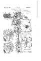
Fig. 1 is a view in longitudinal sectional elevationof a machine embodying the invention;
Fig. 2 is a view partly in elevation an partly in section of a fragmentary portion of the machine looking in a direction opposite that from which the view in Fig. 1 is taken and showingin greater detall certain portions of the structure;
Fig. 3 is a view similar to that shown 111 Fig. 2 with certain of the parts in difi'erent positions from those in which they are shown in Fig. 2;
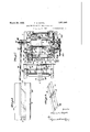
Fig. 4 is a vertical sectional View taken along the line IVIV of Fig. 1, also showing a fragmentary portion of the structure;
Fig. 5 is a vertical sectional elevation taken on the line VV of Fig. 1;
Fig. 6 is a view in side elevatlon of a portion of the structure, looking from the left toward the right in Fig. 5;
F ig. 7 is a sectional plan View taken on the line VII-VII of Fig. 1;
Fig. 8 is-a view in plan of a section of a composite web comprising a plurality of strips of paper and a single strip of highly transparent material; and v Fig. 9 is-a view in perspective of a bag formed from a web of the character shown in Fig. 8.
In the drawings I have shown a frame structure comprising front and rear portions 1 and 2 upon which the operative parts of the structure are mounted and supported.
As already indicated, the machine is adapted to unite the overlapping edges of a plurality of strips adapted for the manufacture of bags commonly known as paper bags, to form a composite web and to produce from the said web bags. One form of composite web is shown in Fig. 8 of the drawings wherein 3 and 4 designate strips of paper or equivalent material which may have greater or less opacity and wherein 5 designates a strip of highly transparent material, such for example as the cellulose hydrate of commerce, which may be identified by the trade name Cellophane. Although I have shown a machine adapted for the formation of a composite web of the character illustrated in Fig. 8, it will be understood that the machine may be adapted to produce webs consisting of a greater or less number of strips united in lengthwise overlapped edge relation, as indicated. The web having been produced in the front half portion of the machine is thereafter formed into tubular shape, severed into sections, and the latter closed at one endto produce bags by means of known construction as indicated and as hereinafter will be -more fully pointed out.
The strips of paper 3 and 4 or equivalent material are supplied in rolls 10 and 11 which are revolubly mounted upon mandrels 12 supported at their opposite ends upon supporting posts 13. The strips 3 and 4 are drawn from the rolls 10 and 11 and are guided about an initial guiding and feeding roll 14 and thence over and partially around a relatively large feed roll or drum 15. During the passage of the strips 3 and 4 around the roll or drum 15 adhesive is applied thereto in a narrow strip in adjoining relation to the inner opposed edges thereof by means of adhesive-applying disks 16 and 17, the applying edges of which are quite narrow, as shown in Fig. 7 of the drawings. These disks 16 and 17 are mounted upon a shaft 18 supported in bearin s 19 provided at the opposite ends of a troug 20, which preferably is detachably mounted upon a rock shaft 21 mounted at its opposite ends in bearings 22 supported upon brackets 23 which-in turn are supported upon the upper part of the port on 1 of the frame structure. It is desirable that the relation of the edges of the disks 16 and 17 be accurately controllable with respect to the adjoining surface of the feed roll or drum 15 and with respect to the outer surfaces of the strips 3 and 4 which travel around the said feed roll or drum in order that the most satisfactory results may be obtained. For this purpose I have provided adjustable means comprisin 25 secured at one end to an end 0% the rock shaft 21 A weight 26 which is suspended by means of a link 27 from the rear or outer end an arm of the said arm tends to cause clockwise movement thereof (see Fig. 6) For regulating the position of said arm and thereby the position of the rock shaft 21 I have provided the said arm with an adjustable screw 28 the lower end of which is in contact with a fixed abutment 29. It will be apparent that by adjusting the screw 28 the position of the shaft 21 is correspondingly adjusted, so that the positions of the edges of the adhesive-applying disks 16 a and 17 with respect to the adjoining opposing surface of the feed roll or drum 15 may be accurately controlled. Means is provided, as will hereinafter be fully described, for preventing any drag between the adhesive-applying disks 16 and 17 and the feed roll 15. The trough 20 is provided with adhesive, as indicated at 30, through which the lower portions of the disks 16 and 17 travel.
The adhesive-applying edges of the disks 16 and 17 are narrow, as is shown in the drawings, so that the adhesive is applied in very narrow lines near the strips3 and 4, such application being made upon the portions of the said strips which may be located between the said disks and the roll or drum 15. It is desirable that small quantities of adhesive be applied and this desire mav be accomplished by the employment of disks having narrow edges, as illustrated. After the application of the adhesive in narrow lines, as indicated, it is desirable that the same be spread so as to prothe inner edges of 36 mounted at its opposite ends in bearings 37. In order to adjust the rock shaft to move said fingers into and out of position to contact with the roll or with the strips of paper 3 and 4 thereon to spread the narrow lines of adhesive as stated, I have provided a member 40 rigidly secured to the end of said rock shaft. The opposite ends of the said member project laterally with respect to the said shaft and are provided with pins 41 and 42 with which a lever 43 is adapted to contact. This lever is pivotally mounted upon the shaft 31 and is provided with an adjustable weight 44. By adjusting said weight upon the lever 43 the force applied by the latter to the pin 42 may be varied. When the lever 43 is in the position shown in Fig. 2 of the drawings it contacts with the pin 42 and turns the member 40 together with the shaft 36 in a direction to cause the outer yielding ends of the fingers to contact with the periphery of the, feed roll 15 or with the strips of paper 3 and 4 which may be traveling around the same. If, however, the lever 43 is turned around the shaft 36 through an angle of approximately 180 into a position substantially opposite to that in wh ch it is shown in Fig. 2. it contacts with the pin 41 and causes a rocking movement of the member and the shaft upon which the latter is mounted to move the fingers 35 into positions out of contact with the feed roll 15 or the strips of paper 3 and 4 thereon. The latter relationhip is shown in Fig. 3 of the drawngs. The extent of such movement is limited by contact of the lower edge of the member 40 with :a stop pin 45. I
In order to unite the lengthwise marginal dge portions of the transparent strip 5 with the inner marginal edge portions of the strips ii and 4 I have mounted a roll of the former strip, indicated at 50, upon a supporting mandrel 51 from which the strip 5 is drawn past and over the guiding rolls 52 and 53, the latter roll being located slightly below the feed roll 15 with its axis a short distance to the left of a vertical plane including the axis of said feed roll. From the latter roll the transparent strip 5 is conducted underneath and into contact with and in superposed relation with respect to the inner marginal edge portions of the strips 3 and 4. The presence of the adhesive previously applied to the marginal edge portions of the strips 3 and 4, as described. causes the marginal edge portions of the transparent strip to adhere to the said strips 3 and 4. After thus uniting the. transparent strip with the other strips the composite web thus produced is carried over and around a guiding and feed roll and from the lattcr it is conducted about the rotatahle. guide rollers 56. 57, 58, 59 and 60. the latter being located near the front end of a tube-forming plate 61, which is of known in nst uel ion. During the passage of the com- ;wsite weh about the. guide roller 60 a line of adhesive 62 is applied to the outer side of one marginal edge portion of one of the strips 3 or 4. In the operation as illustrated and described the line of adhesive 62 is applied in adjoining relation to the outer edge of the strip 3. The line of adhesive 62 is applied by means of a narrow disk 63 supported upon a shaft 64 which in turn is supported at its opposite ends in bearings provided upon the opposite ends of a trough 65 which contains adhesive as indicated at 66 through which the lower portion of the disk 63 travels, as is apparent. The trough 65 is in turn detachably mounted upon a rock shaft 67 which is provided with a laterally extending arm 68 from the outer end of which a weight 69 is suspended, as shown in Fig. 1. The weight 69 operates to hold the edge of the disk 63 yieldingly against either the supporting and guiding roller 60 or against the web of paper which may be traveling around the same. Obviously the shaft 67 may be turned to the right, having reference to Fig. 1, so as to move the edge of the disk 63 out of contact either with the roller 60 or with the web which may be traveling thereover.
The opposite edge portions of the composite web comprising the strips 3, 4, and 5 are turned over the forming plate 61 by known means, including disks one of which is indicated at 70. The draw rolls 71 are of usual construction and engage the outer marginal edge portions of the flattened tubular structure as indicated in Fig. 4 of the drawings, and exert a pull upon the same to draw it and the web through the machine. The flattened.
tubular portion shown in Fig. 4 is cut into sections by severing means of known construction, including a continuously revolving member a portion of which is indicated at 72 and stationary cooperating means indicated at 73 and7 4. The sections having been thus formed are delivered to and carried through means indicated as a whole at 75 (which is of known construction) which is adapted to apply a line of adhesive transversely of the section and in adjoining relation to the forward or lefthand end thereof (having reference to Fig. 1 of the drawings) and to fold the said end as indicated at 76 in Fig. 9. The draw rolls 71 are rotated in directions indicated by the arrows 77 in Fig. 1 by gearing (not shown) intermediate the main drive shaft 80 and the shafts upon which the said rolls are mounted.
If it be. desired that printed matter appear upon the bags, the printing thereof is effected in proper positions upon the web after its formation and prior to the formation thereof into a tubular structure. For that purpose a printing roller 81 may be provided in cooperative relation to the feed roll 55. Ink is applied to the printing roller 81 by means of an ink-applying roller 82 to which ink is supplied by means of the contact therewith of a roller 83 which rotates within a supply of ink- 84 contained in a trough 85. The manner in which rotation of these rollers 81, 82 and 83 is effected will be hereinafter described.
In order to cause the strips 3, 4 and 5 to travel through the machine at a speed corresponding to that of the completed web the flattened tubular formation of which is operated upon by the draw rolls 71 to pull the same through the machine in known manner, I have provided means for positively causing the travel of the said strips through the machine. The said means comprises a shaft 90, preferably jointed, as indicated at 90, Fig. 7, and which is provided at its rear end with a beveled gear 91 which is in engagement with a beveled gear 92 upon the main drive shaft 80. From the latter the draw rolls 71 are driven by gearing, as usual but which is not shown. At its forward end the shaft 90 is provided with a spiral worm gear 95 which is in engagement with a gear 96 mounted frame.
upon one end of a shaft 97. The said shaft is provided atits opposite end with a small gear or pinion 98 which meshes with a gear 99 mounted upon a stud or projection 100 extending laterally from the portion 1 of the The latter gear 99 meshes with a gear 101 which is rigidly mounted upon the shaft 102 of the feed roll 55. A gear 103 also is mounted upon the same shaft outside of the gear 101 and meshes with a relatively large gear 104 mounted upon the adjoining portion of the shaft 105 of the large feed roll 15 and the latter gear is in engagement with a relatively small gear or pinion 106 mounted upon the shaft of the relatively small feed roll 14. Itwill be apparent, therefore, that by properly proportioning the gears the various feed rolls 14, 15 and 55 may be rotated at a speed to effect feeding of the strips 3, 4 and 5 at a speed corresponding to that effected by the draw rolls 71. For the purpose of effecting rotation of the adhesive-applying disks 16 and 17 I have provided upon one end of the relatively large feed roll 1.5 gear teeth 107 which mesh with the teeth of a gear 108 mounted upon the shaft 18. The pitch line of the gear teeth 107 corresponds to the cylindrical peripheral surface of the feed roll 15, and likewise the pitch line of the gear 108 corresponds in diameter to the diameters of the adhesive-applying disks 16 and 17. It follows, therefore, that the peripheries of these disks travel at the same speed as the surface of the cylindrical feed roll 15. In consequence of such equal speed of movement the adhesive-applying disks do not move relatively to the surfaces of the strips 3 and 4 during the a plication of adhesive thereto. Should the dlsks 16 and 17 contact with the said strips such contact would be one of pressure only and would not be likely to injure the same. Preferably the said disks are so adjusted that the edges thereof are located in positions sufficiently close to the strips 3 and 4 to apply thereto adhesive but yet not in actual contact therewith.
For the purpose of actuating the rollers of the inking mechanism I have provided a gear 110 upon the shaft 102, as shown in Figs. 5 and 6 of the drawings, which gear is in engagement with a gear or pinion 111 mounted upon the shaft 112 which supports the printing roller 81. The gear or pinion 111 is in engagement with a gear 1.14 mounted upon the shaft 115 of the roller 82 for applying ink to the printing roller 81. The gear 114 is in mesh with a gear 117 mounted upon the shaft 118 of the roller 83 for applying ink to the roller 82.
Although I have not shown means for positively driving the rolls 52, 53 and 56 it will be understood that if found to be desirable such positive driving means may be provided.
It will be understood by those skilled in the art that the feed rolls 14, 15 and 55 may be driven at a speed so related to the speed of rotation of the draw rolls 71 that the strips 3, 4 and 5 which are united to form the composite web may be caused to travel at a s eed corresponding to that of the web and o the tube structure formed therefrom, the latter structure being shown in flattened condition in the drawings, particularly Fig. 4. By thus providing means for positively feeding the strips through the machine, rendering it unnecessary for the draw rolls 71 to alone effect the feeding movement of the strips and of the web through the machine, I am enabled to operate at a much higher speed than otherwise would be practical. It has been found, as already indicated, that when the draw rolls alone are depended upon for effecting the travel of the strips and the composite web through the machine unequal forces are applied to the strips, which forces are of sufficient magnitude to cause distortion of the strips in the composite web with respect to each other and to cause more or less frequent breakage, particularly of the transparent strip 5. Such distortion causes a deterioration'inthe quality of the bags produced from the composite web, and the time lost in the stopping and starting of the operation of the machine due to breakage is so great as to increase very materially the cost of production. In machines of this character speed of operation is a vital economic factor; hence the practical importance of the means provided by me, which enables the machine to be operated continuously at high speed without interruption due to breakage of any of the strips or any part of the web structure and without distortion of the strips relatively to each other.
Although I have described the machine embodying my invention particularly with rev paper sheets none of which is transparent.
Although I have illustrated my invention as employing three sheets of flexible material 'for the manufacture of bags, one of which sheets is transparent, yet, as hereinbefore clearly indicated, it is to be understood that a greater or less number of sheets may be employed, for example, a single transparent sheet or strip and a single sheet of other flexible material may be employed. It follows of course that when two s eets are employed, but one of the cement or adhesive-applying disks 16 or 17 is employed. One of these disks may be removed if desired, but even if not removed the accuracy of adjustment is such that probably if the sheet 4, for example, were omitted the edge of the disk 17 would not contact with'the roller 15.
Having thus described my, invention, what I claim and desire'to secure by Letters Patent is:
1. A bag-making machine comprising means for forming a continuous composite web of independent sections of flexible sheet material into a tube, means operating to draw said tube and composite web through the said machine, and means operating to cause a positive movement of said continuous web and the component parts of the same toward said drawing means at a speed substantially equal to that caused by the said drawing means.
2. A bag-making machine which is adapted for the making of bags from a composite web of sheet material, comprising means for positively feeding a lurality of strips of sheet material throug the said machine, means for applying adhesive to one of the said strips along a line in adjoining relation to one edge thereof, means for bringing the said strips together with the said adhesive located between overlying marginal edge portions of the said strips, means for forming the composite web thus produced into a tube, and means for thereafter severing the said tube into sections and forming the latter into bags.
3. A bag-making machine which is adapted for the manufacture of bags from a composite web of sheet material comprising a plurality of strips one of which is transparent, which machine comprises feed rolls for causing the said stri s to travel through the said machine, adjusta ly supported means for applying adhesive to the marginal edge portion of at least one of said strips, means for thereafter bringing the said strips together with the said adhesive located between overlapping edge portions thereof whereby the said strips are secured together to form a I composite web, means for applying a line of adhesive to the said web in adjoining relation to one edge thereof, means for forming the said web into a tube, and means for thereafter severing the said web into sections and forming the latter into bags.
4. A bag-making machine which is adapted for the manufacture of bags from a comp0s1te web of sheet material comprising a plurality of strips one of which is transparent, which machine comprises feed rolls for causlng the said strips to travel through the sa d machine, means for positively driving said feed rolls, adjustably supported-means for applying adhesive to a marginal edge portion of at least one of said strips means for thereafter bringing the sai strips together with the said adhesive located between overlapping edge portions thereof whereby the said strips are secured together to form a composite web, means for applying a line of adhesive to the said web in adjoining relation to one edge thereof, means for forming the said web into a tube, and means for thereafter severing the said web into sections and forming the latter into bags.
5. A bag-making machine adapted for the manufacture of bags from a plurality of strips one at least of-which consists of paper and one at least of which consists of highly transparent material, which machine com-- prises a plurality of feed rolls for feeding the said strips through the machine, means for uniting the said strips in lengthwise overlapping edge relation to each other to form a composite web, means for forming said web into a tube, draw rolls engaging the tube thus formed and operating to draw the same through the said machine, and means for causing rotation of said feed rolls at a speed sufficient to cause feed of the said strips at a speed corresponding to that imparted to the said tube and web by the said draw rolls.
6. A bag-making machine adapted for the manufacture of bags from a plurality of strips of flexible cellulosic material one at least of which is transparent, which machine comprises supply rolls of the said strips, feed rolls for drawing the said strips from the said supply rolls and causing the same to travel through the said machine, means for applying adhesive to the edge portion of at least one of said strips, means for uniting the said strips in lengthwise overlapping edge relation to each other to form a composite web, means for forming the said web into a tube, means in engagement with the said tube and operating to draw the same through the machine, a main drive shaft, and gear connections interposed between the said shaft, and the said feed rolls which gear connections are proportioned so as to drive the said feed rolls at a speed to cause the said strips to travel through the machine at a speed corresponding to that of the speed of travel of the composite web and tube formed therefrom through the said machine.
7 A bag-making machine adapted for the manufacture of-paper bags from a plurality of strips at least one of which istransparent, which machine comprises a plurality of suppl rolls of the said strips, a plurality of feed ro ls over which the said strips are adapted to pass and by which they are adapted to be drawn from the said supply rolls and caused to travel through the said machine, a disk adapted to apply a line of adhesive to one of the said strips other than the transparent strip along a line in adjoining relation to an edge thereof, means for controlling the position of the said disk with respect to an ad oin" ing feed roll, means for bringing the said transparent and other strips together in lengthwise overlapping edge relation to each other, the said overlappin edges being secured together by the sai adhesive, means for forming the composite web thus produced into a tube, means in engagement with the said tube and operating to draw the same and the web through the said machine, a main drive shaft and gear connections between the said shaft and the said feed rolls whereby the latter are adapted to be driven to cause positive traveling movement of the said strips through the said machine, the said gear connections being so proportioned as to cause the said strips to move at a speed substantially the same as that of the speed at which the said tube andweb are caused to travel through the said machine, and means for rotating the said adhesive-applying disk at a speed to cause its periphery to move in unison with the periphery of the feed roll with which it cooperates.
8. A bag-making machine adapted for the manufacture of bags from a plurality of paper strips and a transparent strip, which machine comprises a plurality of feed rolls for causing the said strips to travel through the said machine, means comprising a plurality of spaced disks adjustably related'to one of the said rolls for applying lines of adhesive to the said paper strips in adjoining relation to the inner spaced opposing edges thereof, means for spreading the said lines of adhesive, means for relating the said transparent strip to the inner edge portions of the said paper strips with the opposite edges of the said transparent strip overlying the inner edges of the said paper strips and being secured thereto by the said adhesive, means for forming the web produced by the uniting of the said strips into a tube, means for engaging the said tube and drawing the same and the web through the said machine, a drive shaft, and gear connections between the said drive shaft and the said feed rolls for driving the latter at a speed to cause travel of the said strips at substantially the same as that of the said tube and .Web.
9. A machine for making bags from a plu rality of strips of cellulosic material, one
at least of which is transparent, comprising means for enga ing and positively driving the said strips t rough the said machine toward the bag-forming part. thereof, means for applying adhesive to a marginal edge portion of one of said strips, and means for bringing said strips together with certain of their edges in lengthwise overlapped relation to each other whereby the said edges are secured together by the said adhesive.
10. A machine for making bagsfrom three strips of cellulosic material, the central one of which is transparent, comprising means for supporting rolls of material for supplying the two outside strips in vertical spaced planes, means for supporting a roll of transparent material, means positively driving the said strips through the said machine toward the bag-forming mechanism thereof, means for applying a line of adhesive to the inner edge portion of each of the two outside strips, and means for bringing the said transparent strip into position with its opposite edge portions overlapping the inner marginal ed e portions of the two outer strips and over ying the adhesive previously applied thereto, whereby the lengthwise marginal overlapped edge portions thereof are secured together.
11. A machine for making bags from a plurality of strips of cellulosic material, comprising feed rolls, means for causing positive rotation of said rolls to effect feeding movement of said strips through the said for engaging and machine toward the bag-forming part theremove at the same speed as that o the peripheral surface of the said feed roll.
12. A machine for making bags from a plurality of strips of cellulosic material one at least of which is transparent, comprising a plurality of rotative supports for supporting rolls of said strips, feed rolls portions of the peripheral surfaces of which are engaged by the said strips, means for rotatively driving the said feed rolls to cause a positive feeding movement of the said strips through the said machine, an adhesive-applying disk for applying adhesive to one of said stri s, means containing a supply of adhesive or the said disk, means for supporting said disk in adjoining relation to one of the said feed rolls, means for adjusting the said disk with relation to the said last-mentioned feed roll to position its peripheral edge in desired relation to the peri heral surface of the said feed roll, means gr rotating said disk at a speed to cause its peripheral ed e to move at a speed identical with that of t e movement of the peripheral surface of the said feed roll, the ad oin1ng portions of the disk and feed roll moving in the same direction, and means for bringing said strips together with certain of their edges in lengthwise overlapped relation to each other, whereby the said edges are secured together by the said adhesive.
In testimony that I claim the foregoing as my invention I have hereunto signed my name this 4th day of June, A. D. 1929.
THOMAS M. ROYAL.
Priority Applications (1)
| Application Number | Priority Date | Filing Date | Title |
|---|---|---|---|
| US368519A US1851648A (en) | 1929-06-05 | 1929-06-05 | Machine for making cellophane bags |
Applications Claiming Priority (1)
| Application Number | Priority Date | Filing Date | Title |
|---|---|---|---|
| US368519A US1851648A (en) | 1929-06-05 | 1929-06-05 | Machine for making cellophane bags |
Publications (1)
| Publication Number | Publication Date |
|---|---|
| US1851648A true US1851648A (en) | 1932-03-29 |
Family
ID=23451586
Family Applications (1)
| Application Number | Title | Priority Date | Filing Date |
|---|---|---|---|
| US368519A Expired - Lifetime US1851648A (en) | 1929-06-05 | 1929-06-05 | Machine for making cellophane bags |
Country Status (1)
| Country | Link |
|---|---|
| US (1) | US1851648A (en) |
-
1929
- 1929-06-05 US US368519A patent/US1851648A/en not_active Expired - Lifetime
Similar Documents
| Publication | Publication Date | Title |
|---|---|---|
| US2047745A (en) | Multiple compartment bag and process of making same | |
| US2145636A (en) | Apparatus for manufacturing treansparent cellulosic tubes | |
| US1851648A (en) | Machine for making cellophane bags | |
| US2054406A (en) | Universal bag machine | |
| US1691027A (en) | Envelope machine | |
| US2100519A (en) | Bag and like tubing machine | |
| US2147856A (en) | Bag manufacture | |
| US2119951A (en) | Process and apparatus for the manufacture of envelopes, bags, and similar articles | |
| US2296146A (en) | Apparatus for applying supplemental members to bag ends | |
| US1659453A (en) | Fabric-cutting apparatus | |
| US1989943A (en) | Apparatus for use in connection with the making of bags | |
| US491861A (en) | smith | |
| US1583392A (en) | Apparatus for making paper bags | |
| US2587273A (en) | Machine for making corrugated paperboard | |
| US1466101A (en) | Blas-flap stock cutting and applying machine | |
| US1551924A (en) | Envelope-making machine | |
| US283890A (en) | Paper-bag machine | |
| US1020773A (en) | Paper-bag machine. | |
| US1308354A (en) | heywoqd | |
| US1503155A (en) | Machine for the manufacture of envelopes | |
| US1651627A (en) | Machine for making envelopes | |
| US281619A (en) | cbowell | |
| US255204A (en) | Peters | |
| US1253383A (en) | Envelop-machine. | |
| US1714585A (en) | Bag machine |