US1851647A - Target actuating and resetting mechanism - Google Patents
Target actuating and resetting mechanism Download PDFInfo
- Publication number
- US1851647A US1851647A US429151A US42915130A US1851647A US 1851647 A US1851647 A US 1851647A US 429151 A US429151 A US 429151A US 42915130 A US42915130 A US 42915130A US 1851647 A US1851647 A US 1851647A
- Authority
- US
- United States
- Prior art keywords
- target
- spring
- aperture
- pistol
- targets
- Prior art date
- Legal status (The legal status is an assumption and is not a legal conclusion. Google has not performed a legal analysis and makes no representation as to the accuracy of the status listed.)
- Expired - Lifetime
Links
- 230000007246 mechanism Effects 0.000 title description 16
- 230000005484 gravity Effects 0.000 description 6
- 238000004804 winding Methods 0.000 description 3
- 230000035939 shock Effects 0.000 description 2
- 230000003028 elevating effect Effects 0.000 description 1
Images

Classifications
-
- A—HUMAN NECESSITIES
- A63—SPORTS; GAMES; AMUSEMENTS
- A63F—CARD, BOARD, OR ROULETTE GAMES; INDOOR GAMES USING SMALL MOVING PLAYING BODIES; VIDEO GAMES; GAMES NOT OTHERWISE PROVIDED FOR
- A63F9/00—Games not otherwise provided for
- A63F9/02—Shooting or hurling games
- A63F9/0204—Targets therefor
- A63F9/0243—Movable targets
-
- A—HUMAN NECESSITIES
- A63—SPORTS; GAMES; AMUSEMENTS
- A63F—CARD, BOARD, OR ROULETTE GAMES; INDOOR GAMES USING SMALL MOVING PLAYING BODIES; VIDEO GAMES; GAMES NOT OTHERWISE PROVIDED FOR
- A63F2250/00—Miscellaneous game characteristics
- A63F2250/18—Use of resilient or deformable elements
- A63F2250/186—Spring
Definitions
- My invention relates to new and useful imthen aim and fire the gun at the appearing provements in target practice machines, and objects.
- Still another object of the invention is to erating, that is, revolving and resetting the so connecta light to the mechanism that as 5 targets. soon as the objects start to appear in front 55 Still another object of the invention is to of .the aperture they will be illuminated provide a mechanism that may be easily atwhile, on the other hand, the light will not taclied to the several forms of target pracburn unless the birds are revolving.
- the mecha- Still another object of the invention is to nism will be all self-contained, easily set and fasten .all of the part-s to a front plate, so 60 automatically operated after being set. that this may readily be fitted to the rear of l/Vith a number of target practice machines the target practice machines now in use and now in service, the different mechanisms are thus call for but little change in the present electrically operated, and in case of a short structures.
- the operator is apt to receive a seri- Still another object of the invention is to 65 ous shock.
- the machines are provide a returning fan, so that the bullets electrically operated, it is necessary to conafter being fired will gravitate toward the, nect them to the lighting current and they forward end of the machine and may then cannot, therefore, be moved readily from one be again replaced in the pistol.
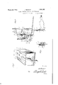
- FIG. l is a perspective of a target practice the cabinet. machine with my improved attachment Another object of the present invention, mounted in the rear thereof;
- a spring motor mech- Fig. 2 is a rear view of the plate and spring 80 anism to be fitted in the rear of these target motor device showing the gear train and the practice machines, which will be wound by manner in which the same is set in motion the movement of a lever which is operated and the manner of mounting the two little when the coin is inserted in the pistol and batteries for the illuminating light;
- F ig. 8 is a side View, parts being' shown in S5 objects to be hit, such as representations of an object, or'plurality of objects, mounted SQCOIIS t about a shaft will intermittently appear be- F18* 4 1S T fragmentary Sectlol VlfW fore an aperture, so that the player of the showing more indetail the manner in which game or the one practicing will try to hij, the several pmions and gears are mounted on the object before it disappears from before the hafti. the aperturet Igig. tlis la IragnientaFry sgectlilonal vitlw L o a en on ie ine e* o i.g.
- FIG. 6 is a diagrammatic View Showing the aft being knocked dOWDySO that all that S connection between the pistol cocking mechnecessary fOr the 911 tStlIlg hlS Sklll 1S t0 anism and the rack bar for windingthe mosimply put in a coin, operate a lever, which tor.
- a target practice machine comprising a casing 1, in which is mounted the pistol 2, which is universally mounted at 3 for shooting at an object to the rear of the casing 4. It will be understood that the pistol and its mounting per sey forms no part of my invention and any form of casing and pistol and the manner of operating the pistol may be used.
- a front plate 5 to which is secured a casing 6, from which extends the portion 7 which forms a return pan f or the bullets (not shown) that are to be fired from the pistol, 1t will be seen that the front plate 5 is elevated a little with regard to'this pan, so that if the bullets pass-through an aperture, short ly to be mentioned, they mayfall down on the pan and pass beneath the lower edge of the plate 5 or if they strike the outside of the plate 5 they willV simply drop on the pan and return to the front of the cabinet.
- a footor stand 8 is riveted, as at 9, to the casing 6 and this foot foot willbe secured to the lower part of the bok or cabinet.
- Y Slottedly held to the foot 8 by the small bolt 10 is the rack bar 11 which, in turn, operates the pinion 12, which is drive shaft A.
- the large gear 13 which, in turn, is provided vre0 ⁇ bar 11.
- the lever when thehandle operated, the nose 28 will with the various pawls 14, which engage with the ratchetvgear 15, which is likewise keyed to the shaft A.
- a spring 22,'.one end Yof which is fastened, as at 23, to the rear cover plate, and
- Fig. 1 there may be seen the handle 26 to operate a lever 27 after a coin has been inserted in the slot, the nose 28 of the lever being widened out and opening 29 in the foot 8 and beneath the rack 27 is Varranged so that Vder the light, so that when extending through an Y be forced forwardly, thus elevating the rack bar 11 which, it will be remembered, engages with the pinion 12 on the shaft A and will thus wind up the spring.
- the upper end of the rack bar is provided with a slot 3() and guided by a pin 31 and the upper end of this rack bar makes an electrical contact, which will be later described. Also, the operation of this lever 27 cocks the pistol.
- pinned on the shaft C is a sleeve 32, while the outer end of the shaft C is mounted within the plate 5.
- the cross bar 33 mounted on this sleeve is the cross bar 33, to the ends of which are mounted the targets 34, which may-follow the outline of a bird or any fancifulA object.
- these targets 34 have a lug 35 Y to the rear thereof to Vbe pivoted within the ends of the cross bar. 1t might be wellto mention here that there is an aperture. 36 in the plate 5, so that when the cross bar is in its vertical position, the upper target will be in front of the aperture, as shown in the dotted lines in Fig. 3. Y
- a target practice mechanism in the form of a unit comprising a front plate, a spring motor, said plate provided with an aperture therein, targets to be revolved by said spring motor and passing in front of said aperture and said targets pivotally mounted so that the same may be forced rearwardly when struck, said targets also arranged to right themselves by gravity before they approach said aperture, rack and gear means for winding said motor, a pan connected with the attachment to provide a return for the bullets projected at said ta-rgets, and a lighting mechanism for illuminating the targ'ets connected with the rack whereby said lighting mechanism will be automatically turned on during the revolutions of said motor.
- a target actuating and resetting mechanism comprising a unit, said unit consisting of a face plate, a casing behind said face plate and a spring motor attached to the rear of said casing, a rack cooperating with a gear in said spring motor for winding said motor, an electric lighting system for illuminating the targets connected with said rack whereby the system will be turned on when the motor is in it-s wound condition, a pan connected with the unit for allowing the bullets projected at said targets to run forwardly beyond the plate, said plate provided with an aperture, and revolving targets c011- nected with the spring motor, whereby said targets rotatably successively appear in front of said aperture and said targets being pivotally mounted whereby the same may fall rearwardly when struck and also so mounted as to right themselves by gravity before they appear in fro-nt of the aperture.
- a mechanism for target practice Inachines comprising a unitary structure, said structure consisting of a front plate, a casing and a spring motor attached to said casing, said front plate provided with an aperture, targets mounted on the shaft of the motor and to appear successively in front of the aperture, said targets pivotally mounted at their bases whereby the same may be knocked rearwardly and by gravity will right themselves before they appear in front of the aperture, a rack bar cooperating with said motor to wind the same when the rack bar is actuated, a light on said unit, battery clips for holding electric batteries, and the rack bar forming an electrical connection between the battery and the light to turn on the current after said rack bar has wound up the motor.
Landscapes
- Engineering & Computer Science (AREA)
- Multimedia (AREA)
- Toys (AREA)
Description
March 29, 1932. J. REMONTE TARGET ACTUATING A ND RESETTING MECHANISM Filed Feb. 17, 1930 2 Sheets-Sheet l i @n i 5 l s z z l 1 i March 29, 1932. J. REMQNTE TARGET ACTUATING AND RESETTING MECHANISM Filed Feb. 17, 1930 2 Sheets-Sheec 2 gjm/vento@ JUHN Hman/7E Patented Mar. 29, 1932 I 1 STTS PATT OFIE JOHN REMONTE, OF CORPUS CHRISTIE, TEXAS TARGET ACTUATING AND RESETTING MECHANISM Application led February 17, 1930. Serial No. 429,151.
My invention relates to new and useful imthen aim and fire the gun at the appearing provements in target practice machines, and objects.
more particularly to the mechanism for op- Still another object of the invention is to erating, that is, revolving and resetting the so connecta light to the mechanism that as 5 targets. soon as the objects start to appear in front 55 Still another object of the invention is to of .the aperture they will be illuminated provide a mechanism that may be easily atwhile, on the other hand, the light will not taclied to the several forms of target pracburn unless the birds are revolving.
tice machines now in use, so that the mecha- Still another object of the invention is to nism will be all self-contained, easily set and fasten .all of the part-s to a front plate, so 60 automatically operated after being set. that this may readily be fitted to the rear of l/Vith a number of target practice machines the target practice machines now in use and now in service, the different mechanisms are thus call for but little change in the present electrically operated, and in case of a short structures.
circuit the operator is apt to receive a seri- Still another object of the invention is to 65 ous shock. Again, where the machines are provide a returning fan, so that the bullets electrically operated, it is necessary to conafter being fired will gravitate toward the, nect them to the lighting current and they forward end of the machine and may then cannot, therefore, be moved readily from one be again replaced in the pistol.
90 place to another. With these and other objects in view, the 70 It is well known to those familiar with this invention consists in certain new and novel subject that these target practice machines arrangements and combination of parts, as Compris@ a box or Casing, from which eX- will be hereinafter more fully described and A tends the buttof a pistol and which pistol pointed out in the claims.
has a limited traversing movement, the ob- Referring now to the drawings showing a 75 ject being to sight the pistol and fire at a preferred embodiment of my invention.
moving or stationary object at the rear of Fig. l is a perspective of a target practice the cabinet. machine with my improved attachment Another object of the present invention, mounted in the rear thereof;
therefore, is to provide a spring motor mech- Fig. 2 is a rear view of the plate and spring 80 anism to be fitted in the rear of these target motor device showing the gear train and the practice machines, which will be wound by manner in which the same is set in motion the movement of a lever which is operated and the manner of mounting the two little when the coin is inserted in the pistol and batteries for the illuminating light;
after the lever movement has been completed, F ig. 8 is a side View, parts being' shown in S5 objects to be hit, such as representations of an object, or'plurality of objects, mounted SQCOIIS t about a shaft will intermittently appear be- F18* 4 1S T fragmentary Sectlol VlfW fore an aperture, so that the player of the showing more indetail the manner in which game or the one practicing will try to hij, the several pmions and gears are mounted on the object before it disappears from before the hafti. the aperturet Igig. tlis la IragnientaFry sgectlilonal vitlw L o a en on ie ine e* o i.g. s owing e Stili anothr blec of dth. mveblotl lo manner of mounting the birds dn the central pwvlce a Spmb m0 or el we W einem e shaft, so that they will automatically reset themselves g birds, will automatically reset themselves Fig. 6 is a diagrammatic View Showing the aft being knocked dOWDySO that all that S connection between the pistol cocking mechnecessary fOr the 911 tStlIlg hlS Sklll 1S t0 anism and the rack bar for windingthe mosimply put in a coin, operate a lever, which tor.
cocks the pistol and starts the machine, and Referring now more specifically to the sevkeyed to the main eral views, and to Fig. 1 in particular, there is shown a target practice machine comprising a casing 1, in which is mounted the pistol 2, which is universally mounted at 3 for shooting at an object to the rear of the casing 4. It will be understood that the pistol and its mounting per sey forms no part of my invention and any form of casing and pistol and the manner of operating the pistol may be used.
In the rear of the cabinet 4, there is mounted a front plate 5, to which is secured a casing 6, from which extends the portion 7 which forms a return pan f or the bullets (not shown) that are to be fired from the pistol, 1t will be seen that the front plate 5 is elevated a little with regard to'this pan, so that if the bullets pass-through an aperture, short ly to be mentioned, they mayfall down on the pan and pass beneath the lower edge of the plate 5 or if they strike the outside of the plate 5 they willV simply drop on the pan and return to the front of the cabinet. For securing theplate 5 and its associated parts in place, as may be seen, a footor stand 8 is riveted, as at 9, to the casing 6 and this foot foot willbe secured to the lower part of the bok or cabinet. Y Slottedly held to the foot 8 by the small bolt 10 is the rack bar 11 which, in turn, operates the pinion 12, which is drive shaft A. There will also be seen loosely mounted on Vthis shaft A the large gear 13 which, in turn, is provided vre0 `bar 11. The lever when thehandle operated, the nose 28 will with the various pawls 14, which engage with the ratchetvgear 15, which is likewise keyed to the shaft A. 1 Y
Mounted above this shaft A, on the shaft B, is a small gear-16 operated by the gear 13, and likewise to the rear on this shaft is mounted the large gear 17, which latter engages with the'pinion 18 which, in turn, is mounted on the target revolving shaft C. On the shaft C is mounted the gear 19, which meshes with a suitably mounted pinion 2O on which there is a fan 21, which is common to spring motors for holding down the speed of the gear train. l
Itis thought that this short description of theV gear train and spring motor is sufficient, as it is similar in most'spring motors. Y
Referring to Fig. 2 for the moment, there may be seen a spring 22,'.one end Yof which is fastened, as at 23, to the rear cover plate, and
the other end 24 of which is fastened to the main drive shaft A. A small guard 25 is seen also fastened at the end 23 of the spring Vand extends up in front of the flat coil spring to hold the same inplace.
In Fig. 1, there may be seen the handle 26 to operate a lever 27 after a coin has been inserted in the slot, the nose 28 of the lever being widened out and opening 29 in the foot 8 and beneath the rack 27 is Varranged so that Vder the light, so that when extending through an Y be forced forwardly, thus elevating the rack bar 11 which, it will be remembered, engages with the pinion 12 on the shaft A and will thus wind up the spring. The upper end of the rack bar is provided with a slot 3() and guided by a pin 31 and the upper end of this rack bar makes an electrical contact, which will be later described. Also, the operation of this lever 27 cocks the pistol.
Before following through the operation of the gear train, it .will be noticed that pinned on the shaft C is a sleeve 32, while the outer end of the shaft C is mounted within the plate 5. Also mounted on this sleeve is the cross bar 33, to the ends of which are mounted the targets 34, which may-follow the outline of a bird or any fancifulA object. It will be noticed that these targets 34 have a lug 35 Y to the rear thereof to Vbe pivoted within the ends of the cross bar. 1t might be wellto mention here that there is an aperture. 36 in the plate 5, so that when the cross bar is in its vertical position, the upper target will be in front of the aperture, as shown in the dotted lines in Fig. 3. Y
Should this target be struck and knocked to the position shown in Fig. 3, it will, by gravity, when revolving, right itself to a vertical position, as also may be seen in Fig. 3. 1n other words, by providing a lug to the rear of the target, the weight of the target being olf-centerwill gravitate to a vertical position, where it will remain during the rest of its revolutions until knocked down by another bullet.
Referring for the moment now to the manner of illuminating the .target while the mechanism is in operation, it will be seen that the Lupper end 37 of the rack bar 11 will contact with the spring finger (properly insulated), as at 39,while from the spring nger, there is a circuit connected with a small light 40, which is mounted on the casing6,
while casing has an aperture 41 directly unthe light is on, it will .illuminate the target. The circuit then is connected to the small cells 42 that are respectively held in place by the clips 43, and one of the leads from the batteries may be grounded to the winding mechanism to thus complete the circuit. Therefore, when the rack bar is in operated position, it will contact with the spring finger until it has again descended and the motor is unwound.
l Operation l The operation is exceedingly simple. VIt is only necessary to operate the handle 26 to operate the lever 27 which will cock the pistol and raise the rack bar which,inturn,willwind up the spring through the pinion 12. rlhe ratchets engaging the pawls will cause spring several. pinions and gears described willop- Vto drive the large gear 13 and throughthe ily understood. The targets 34 will intermittently appear in front of the aperture and the person practicing will then fire the pistol. If the operator hits the target, it will be knocked rearwardly, that is, on its pivot point, and in its descending motion will right itself by gravity, so that when it again appears in front of the aperture it will be in its upright position. The light will remain lighted until the rack bar has disengaged itself from the spring finger 38, as will be readily understood. The bullets will then, by gravity, fall down the pan 7, where they may be again replaced within the pistol.
From the foregoing, it will be seen that I have designed an attachment or target setting mechanism for target practice machines, that is, wholly operated by a spring motor, wherein the same may be either built with new machines or may be attached to machines already in use. Furthermore, the targets are illuminated by small light cells that may be replaced when necessary, so that there is no chance of the operator receiving the shock. Again, the machines being self-contained may be moved about without any reference to any connections with the lighting circuit.
Finally, it will be seen that it takes only a short stroke of the lever to wind up the machine and that it is not necessary to reset the targets by hand if the operator is skilled enough to knock them down. It will also be seen that the whole device is very compact and all of the parts are mounted on a plate and a bracket, which may be easily fitted within a target practice machine.
Many slight changes might be made without in any way departing from the spirit and scope of the invention.
Having thus described my invention, what I cla-im as new and desire to secure by Letters Patent is:
l. A target practice mechanism in the form of a unit comprising a front plate, a spring motor, said plate provided with an aperture therein, targets to be revolved by said spring motor and passing in front of said aperture and said targets pivotally mounted so that the same may be forced rearwardly when struck, said targets also arranged to right themselves by gravity before they approach said aperture, rack and gear means for winding said motor, a pan connected with the attachment to provide a return for the bullets projected at said ta-rgets, and a lighting mechanism for illuminating the targ'ets connected with the rack whereby said lighting mechanism will be automatically turned on during the revolutions of said motor.
2. A target actuating and resetting mechanism comprising a unit, said unit consisting of a face plate, a casing behind said face plate and a spring motor attached to the rear of said casing, a rack cooperating with a gear in said spring motor for winding said motor, an electric lighting system for illuminating the targets connected with said rack whereby the system will be turned on when the motor is in it-s wound condition, a pan connected with the unit for allowing the bullets projected at said targets to run forwardly beyond the plate, said plate provided with an aperture, and revolving targets c011- nected with the spring motor, whereby said targets rotatably successively appear in front of said aperture and said targets being pivotally mounted whereby the same may fall rearwardly when struck and also so mounted as to right themselves by gravity before they appear in fro-nt of the aperture.
3. A mechanism for target practice Inachines comprising a unitary structure, said structure consisting of a front plate, a casing and a spring motor attached to said casing, said front plate provided with an aperture, targets mounted on the shaft of the motor and to appear successively in front of the aperture, said targets pivotally mounted at their bases whereby the same may be knocked rearwardly and by gravity will right themselves before they appear in front of the aperture, a rack bar cooperating with said motor to wind the same when the rack bar is actuated, a light on said unit, battery clips for holding electric batteries, and the rack bar forming an electrical connection between the battery and the light to turn on the current after said rack bar has wound up the motor.
In testimony whereof I affix my signature.
JOHN REMONTE.
Priority Applications (1)
| Application Number | Priority Date | Filing Date | Title |
|---|---|---|---|
| US429151A US1851647A (en) | 1930-02-17 | 1930-02-17 | Target actuating and resetting mechanism |
Applications Claiming Priority (1)
| Application Number | Priority Date | Filing Date | Title |
|---|---|---|---|
| US429151A US1851647A (en) | 1930-02-17 | 1930-02-17 | Target actuating and resetting mechanism |
Publications (1)
| Publication Number | Publication Date |
|---|---|
| US1851647A true US1851647A (en) | 1932-03-29 |
Family
ID=23702009
Family Applications (1)
| Application Number | Title | Priority Date | Filing Date |
|---|---|---|---|
| US429151A Expired - Lifetime US1851647A (en) | 1930-02-17 | 1930-02-17 | Target actuating and resetting mechanism |
Country Status (1)
| Country | Link |
|---|---|
| US (1) | US1851647A (en) |
Cited By (2)
| Publication number | Priority date | Publication date | Assignee | Title |
|---|---|---|---|---|
| US6217026B1 (en) * | 1998-11-14 | 2001-04-17 | Kwang Su Kang | Game system shooting at the target by means of a pneumatic gun |
| US20080164657A1 (en) * | 2007-01-08 | 2008-07-10 | Brent Sheldon | Moving target practice apparatus |
-
1930
- 1930-02-17 US US429151A patent/US1851647A/en not_active Expired - Lifetime
Cited By (4)
| Publication number | Priority date | Publication date | Assignee | Title |
|---|---|---|---|---|
| US6217026B1 (en) * | 1998-11-14 | 2001-04-17 | Kwang Su Kang | Game system shooting at the target by means of a pneumatic gun |
| US6338487B2 (en) | 1998-11-14 | 2002-01-15 | Andamiro Company, Ltd. | Game system shooting at the target by means of a pneumatic gun |
| US20080164657A1 (en) * | 2007-01-08 | 2008-07-10 | Brent Sheldon | Moving target practice apparatus |
| US7611147B2 (en) * | 2007-01-08 | 2009-11-03 | Brent Sheldon | Moving target practice apparatus |
Similar Documents
| Publication | Publication Date | Title |
|---|---|---|
| US3089476A (en) | Projectile apparatuses | |
| US4296929A (en) | Electric eye actuated gun arcade | |
| US1552191A (en) | Target-throwing apparatus | |
| US1547834A (en) | Miniature shooting gallery | |
| US1851647A (en) | Target actuating and resetting mechanism | |
| US2722211A (en) | Mechanical projectors | |
| US2171295A (en) | Card and dice game | |
| US2448024A (en) | Machine gun firing rate control mechanism | |
| US2111952A (en) | Amusement apparatus | |
| US2531608A (en) | Bombing game | |
| US2286151A (en) | Game | |
| US2161012A (en) | Shooting-gallery game | |
| US2285292A (en) | Dispensing device | |
| US4335880A (en) | Electric eye actuated gun arcade | |
| US2269256A (en) | Gun game | |
| US2148612A (en) | Electric target range | |
| US2247751A (en) | Gun game | |
| US2109860A (en) | Amusement device | |
| US1539648A (en) | Amusement apparatus | |
| US2254952A (en) | Target apparatus | |
| US2185628A (en) | Target | |
| US2070529A (en) | Marksmanship practicing device | |
| US2206318A (en) | Ball game apparatus | |
| US1650935A (en) | Target game | |
| US2135667A (en) | Target device |