US185162A - Improvement in corn-planters - Google Patents
Improvement in corn-planters Download PDFInfo
- Publication number
- US185162A US185162A US185162DA US185162A US 185162 A US185162 A US 185162A US 185162D A US185162D A US 185162DA US 185162 A US185162 A US 185162A
- Authority
- US
- United States
- Prior art keywords
- band
- corn
- axle
- hopper
- cups
- Prior art date
- Legal status (The legal status is an assumption and is not a legal conclusion. Google has not performed a legal analysis and makes no representation as to the accuracy of the status listed.)
- Expired - Lifetime
Links
- 240000008042 Zea mays Species 0.000 description 9
- 235000005824 Zea mays ssp. parviglumis Nutrition 0.000 description 9
- 235000002017 Zea mays subsp mays Nutrition 0.000 description 9
- 235000005822 corn Nutrition 0.000 description 9
- XEEYBQQBJWHFJM-UHFFFAOYSA-N Iron Chemical compound [Fe] XEEYBQQBJWHFJM-UHFFFAOYSA-N 0.000 description 5
- 240000008691 Sagittaria lancifolia Species 0.000 description 5
- 229910052742 iron Inorganic materials 0.000 description 3
- ATJFFYVFTNAWJD-UHFFFAOYSA-N Tin Chemical compound [Sn] ATJFFYVFTNAWJD-UHFFFAOYSA-N 0.000 description 2
- 240000001931 Ludwigia octovalvis Species 0.000 description 1
- 239000000463 material Substances 0.000 description 1
- 230000000284 resting effect Effects 0.000 description 1
- 239000002023 wood Substances 0.000 description 1
- 238000010626 work up procedure Methods 0.000 description 1
Images
Classifications
-
- A—HUMAN NECESSITIES
- A01—AGRICULTURE; FORESTRY; ANIMAL HUSBANDRY; HUNTING; TRAPPING; FISHING
- A01C—PLANTING; SOWING; FERTILISING
- A01C7/00—Sowing
- A01C7/04—Single-grain seeders with or without suction devices
Definitions
- My invention relates to a two-wheeled machine, so constructed as to contain a regular bull-tongue plow, with beam, handle, and other necessary appurtenances.
- the wheels are coupled together by a round axle three feet in length and one and a half inch in diameter.
- This axle is squared at the ends, and passes through a mortise in the center of the wheels, and fastened thereto, so as to revolve with the wheels.
- the axle passes at right angles through two piecesoftii uber, made,pref erably, three inches broad and two and a half inches thick, and about four feet long. They are separated on the axle, near the center, just far enough for the beam containing the bulltongue to work up and down smoothly.
- the front ends run along either side the beam, and are fastened to it by an iron pin passing through them all,-and screwing them loosely together. That part of the axle between these two pieces of timber is uncovered.
- the other parts pass through boxes that may run the whole length, and are bored out just large enough for the axle to revolve freely. The holes in the boxes and cross-timbers, through which the axle passes, come together, and they are fastened securely in front and rear of the axle, so as to keep the machine perfectly squared and true.
- the hopper is large enough to contain about half a bushel of corn, and so arranged as to incline the corn to the center.
- This hopper rests on the cross-pieces and the casings of the axle as a fixture.
- a roller Near the top of the front part of the hopper is a roller three-fourths of an inch wide and about ouehalf an inch in diameter to assist in carrying the band.
- This roller is supported on a separate standard from the hopper, to which it is screwed adjustably, so as to slide up or down for tightening or loosening the band.
- a tin spout is fastened, which conduets the corn down just in rear of the bulltongue.
- the band passes around the axle, through the hopper, and over the roller at the top of the hopper, and down through the spout.
- tin cups about three-fourths of an inch by one-half an inch are attached. to carry the corn. They fill as they pass up through the corn.
- the corn is prevented from escaping from the hopper at the bottom by means of small blocks of wood attached by small wire rivets to the band between the cups.
- a space say an inch, is left for the cups to lill and empty.
- the blocks or cups are made to fit exactly the hole in the bottom of the'hopper.
- the wheels are about fourteen or fifteen inches in diameter, and may he two or two and a half inches thick, made of plank riveted together crosswise, and banded with hoop-iron.
- the coverers are two small iron teeth, a little oval on the inner sides, fastened in the cross-pieces projecting in rear of the axle, just far enough apart to cut the inner edge of the furrow open by the bull-tongue. These teeth can be shortened or lengthened for depth.
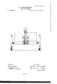
- Figure l represents a plan view of my improved planter; Fig. 2, a longitudinal vertical section through the box and band.
- Fig. 3 is a transverse vertical section in front of the band, showing more particularly the standard which supports the upper roller and the band.
- a A are the longitudinal sills, which support the coverers, and through which the axle passes. ⁇ Upon them and the boxes a a rests the hopper B.
- the axle is shown in section in Fig. 2, with the band carrying the blocks and boxes, which band is supported above by the roller
- the hole in the bottom of the hopper is shown at c in the same ligure, and the spout is represented at cl.
- the beam carrying the bull-tongue is indicated in Figs. 1 and 2 by the letter g, and the figures also show plainly the ordinary supports and connections.
- Fig. 3 shows more clearly the standard with the roller inthe slotted upper Aportion there- Ot', the band i passing over the roller and axle, and the set-screws e e in the slots on the sides, by which the standard may ber'aised” or lowered. It also illustrates. the boxes It h.
- the Wheels may have the ordinary clutches, for preventing reverse movement ot' the band in backing or turning.
- the improved planter consisting of the box B, resting upon the beams A A, and boxes a a, the band t', carrying the blocks and cups, and passing over the axle below and the roller above, and the spout d, attached to the seedbox, and arranged between the beams A A, as and for the purposes set forth.
Landscapes
- Life Sciences & Earth Sciences (AREA)
- Soil Sciences (AREA)
- Environmental Sciences (AREA)
- Cultivation Receptacles Or Flower-Pots, Or Pots For Seedlings (AREA)
Description
R. B. BOATWRIGHT.
CORN-PLANTER. N,185,16Z, y Patented Dc.12,1876.
llIlllIlIlllllllllllll mi; Y.
illllm dgn:
THE GRAPHIC CDJLY Nrrnn TATES REUBEN B. BOATWRIGIIT, OF MARION, VIRGINIA, ASSIGNOR OF ONE-HALF OF HIS RIGHT TO GEORGE W. HENDERLITE, OF SAME PLAGE.
IMPROVEMENT lN CORN-PLANTERS.
Specification forming part of Letters Patent No. 185,162, dated December 12, 1876 application led April 8, 1876'.
To all whom it may concern Be it known that I, REUBEN B. BOAT- WRIGHT, of Marion, in the county of Smyth and State of Virginia, have invented certain new and useful Improvements in Corn-Planters, of which the following is a full, clear, and exact description, reference being had to the accompanying drawings.
My invention relates to a two-wheeled machine, so constructed as to contain a regular bull-tongue plow, with beam, handle, and other necessary appurtenances. The wheels are coupled together by a round axle three feet in length and one and a half inch in diameter. This axle is squared at the ends, and passes through a mortise in the center of the wheels, and fastened thereto, so as to revolve with the wheels. The axle passes at right angles through two piecesoftii uber, made,pref erably, three inches broad and two and a half inches thick, and about four feet long. They are separated on the axle, near the center, just far enough for the beam containing the bulltongue to work up and down smoothly. They run back about twelve or fourteen inches in rear of the axle, and serve as support for the coverers, and also for the hopper to rest upon. The front ends run along either side the beam, and are fastened to it by an iron pin passing through them all,-and screwing them loosely together. That part of the axle between these two pieces of timber is uncovered. The other parts pass through boxes that may run the whole length, and are bored out just large enough for the axle to revolve freely. The holes in the boxes and cross-timbers, through which the axle passes, come together, and they are fastened securely in front and rear of the axle, so as to keep the machine perfectly squared and true. The hopper is large enough to contain about half a bushel of corn, and so arranged as to incline the corn to the center. Through the bottom there passes a hole about three-fourths of an inch square. This hopper rests on the cross-pieces and the casings of the axle as a fixture. Near the top of the front part of the hopper is a roller three-fourths of an inch wide and about ouehalf an inch in diameter to assist in carrying the band. This roller is supported on a separate standard from the hopper, to which it is screwed adjustably, so as to slide up or down for tightening or loosening the band. To this a tin spout is fastened, which conduets the corn down just in rear of the bulltongue. The band passes around the axle, through the hopper, and over the roller at the top of the hopper, and down through the spout. It is preferably threefourths of an inch in width and about nine inches long, to which tin cups about three-fourths of an inch by one-half an inch are attached. to carry the corn. They fill as they pass up through the corn. The corn is prevented from escaping from the hopper at the bottom by means of small blocks of wood attached by small wire rivets to the band between the cups. Just in front of each cup a space, say an inch, is left for the cups to lill and empty. The blocks or cups are made to fit exactly the hole in the bottom of the'hopper. The wheels are about fourteen or fifteen inches in diameter, and may he two or two and a half inches thick, made of plank riveted together crosswise, and banded with hoop-iron. The coverers are two small iron teeth, a little oval on the inner sides, fastened in the cross-pieces projecting in rear of the axle, just far enough apart to cut the inner edge of the furrow open by the bull-tongue. These teeth can be shortened or lengthened for depth.
In the drawings, Figure l represents a plan view of my improved planter; Fig. 2, a longitudinal vertical section through the box and band. Fig. 3 is a transverse vertical section in front of the band, showing more particularly the standard which supports the upper roller and the band.
A A are the longitudinal sills, which support the coverers, and through which the axle passes. `Upon them and the boxes a a rests the hopper B. The axle is shown in section in Fig. 2, with the band carrying the blocks and boxes, which band is supported above by the roller The hole in the bottom of the hopper is shown at c in the same ligure, and the spout is represented at cl. The beam carrying the bull-tongue is indicated in Figs. 1 and 2 by the letter g, and the figures also show plainly the ordinary supports and connections.
Fig. 3 shows more clearly the standard with the roller inthe slotted upper Aportion there- Ot', the band i passing over the roller and axle, and the set-screws e e in the slots on the sides, by which the standard may ber'aised" or lowered. It also illustrates. the boxes It h.
The Wheels may have the ordinary clutches, for preventing reverse movement ot' the band in backing or turning.
The advantages of my invention are its simplicity. All its operations can be easily understood by any ordinary farmer. The materials are all on the farm, and it canr be repaired, or even made by the farmer himselt' or a neighborhood mechanic.
As there is a great diversity of opinion as toA the distance at which corn should be planted, this machine, with a little arrangement of the cups on the band, can be made to drop it at regular intervals, and at any distance at which corn is planted. The length ot' the band, the size ot' the Wheel, the circumference ot the axle given, We know exactly Where to place our cups. For example, it' the Wheels are forty-live inches in circumference, the axle four and a'haltl inches in circumference, and the band nine inches long, the Wheel Will make two revolutions while the -band 'passes around the axle once. Two cups equidistant onY the band would drop the corn forty-five inches apart; four cups would drop it tWenl tyltwo and a halt' inches, Ste.' KIKIOWDgE'there-d fore, these distances We have only to increase or diminish the number of cups, and lengthen 'or slierten the band, to drop it the distance we want.
Having thus fully described my invention,Y
also form support for the hopper, the Whole being,` constructed and arranged as set forth.
2. The band t', carrying blocks and boxes, supported on roller above, and operating` in connection with the hopper, as set forth.
3. The improved planter, consisting of the box B, resting upon the beams A A, and boxes a a, the band t', carrying the blocks and cups, and passing over the axle below and the roller above, and the spout d, attached to the seedbox, and arranged between the beams A A, as and for the purposes set forth.
R. B. BOATWRIGHT. Witnesses:
W. P. FRANCIS, JNO. A. BLoUNT.
Publications (1)
| Publication Number | Publication Date |
|---|---|
| US185162A true US185162A (en) | 1876-12-12 |
Family
ID=2254567
Family Applications (1)
| Application Number | Title | Priority Date | Filing Date |
|---|---|---|---|
| US185162D Expired - Lifetime US185162A (en) | Improvement in corn-planters |
Country Status (1)
| Country | Link |
|---|---|
| US (1) | US185162A (en) |
-
0
- US US185162D patent/US185162A/en not_active Expired - Lifetime
Similar Documents
| Publication | Publication Date | Title |
|---|---|---|
| US185162A (en) | Improvement in corn-planters | |
| US134293A (en) | Improvement in broadcast-seeders | |
| US416498A (en) | Rufus e | |
| US713976A (en) | Grain-drill. | |
| US291402A (en) | Seed planter and fertilizer distributee | |
| US147160A (en) | Improvement in seed-planters | |
| US737678A (en) | Corn-planter. | |
| US113022A (en) | Improvement in grain-drills | |
| US261724A (en) | jones | |
| US132824A (en) | Improvement in corn-planters | |
| US86068A (en) | Improvement in seed and grain-drills | |
| US130521A (en) | Ximprovement i in cotton-seed planters | |
| US161991A (en) | Improvement in seed-sowers | |
| US208848A (en) | Improvement in fertilizer-distributers | |
| US37754A (en) | Improvement in corn-planters | |
| US106859A (en) | Improvement in cotton-seed planters | |
| US82822A (en) | Improvement in grain-drills | |
| US523226A (en) | Combination planter and cultivator | |
| US3870A (en) | Improvement in seed-planters | |
| US408585A (en) | Potato-planter and seed-drill | |
| US9879A (en) | Improvement in seed-planters | |
| US507924A (en) | Seed-planter | |
| US159087A (en) | Improvement in seed-planters | |
| US533924A (en) | Seed-planter and fertilizer-distributing attachment for plows | |
| US127648A (en) | Improvement in corn-planters |