US185161A - Improvement in horseshoe-machines - Google Patents
Improvement in horseshoe-machines Download PDFInfo
- Publication number
- US185161A US185161A US185161DA US185161A US 185161 A US185161 A US 185161A US 185161D A US185161D A US 185161DA US 185161 A US185161 A US 185161A
- Authority
- US
- United States
- Prior art keywords
- die
- shoe
- head
- bed
- pin
- Prior art date
- Legal status (The legal status is an assumption and is not a legal conclusion. Google has not performed a legal analysis and makes no representation as to the accuracy of the status listed.)
- Expired - Lifetime
Links
- XEEYBQQBJWHFJM-UHFFFAOYSA-N Iron Chemical compound [Fe] XEEYBQQBJWHFJM-UHFFFAOYSA-N 0.000 description 10
- 238000003825 pressing Methods 0.000 description 6
- 229910052742 iron Inorganic materials 0.000 description 5
- 238000005452 bending Methods 0.000 description 4
- 238000010276 construction Methods 0.000 description 3
- 238000005096 rolling process Methods 0.000 description 3
- 239000010022 Myron Substances 0.000 description 2
- 241001439614 Myron Species 0.000 description 2
- 230000000881 depressing effect Effects 0.000 description 2
- 230000000994 depressogenic effect Effects 0.000 description 2
- 235000008733 Citrus aurantifolia Nutrition 0.000 description 1
- 240000006909 Tilia x europaea Species 0.000 description 1
- 235000011941 Tilia x europaea Nutrition 0.000 description 1
- 240000008042 Zea mays Species 0.000 description 1
- 235000005824 Zea mays ssp. parviglumis Nutrition 0.000 description 1
- 235000002017 Zea mays subsp mays Nutrition 0.000 description 1
- 235000005822 corn Nutrition 0.000 description 1
- 238000005520 cutting process Methods 0.000 description 1
- 239000004571 lime Substances 0.000 description 1
- 238000004080 punching Methods 0.000 description 1
- 230000000717 retained effect Effects 0.000 description 1
- 238000007493 shaping process Methods 0.000 description 1
- 238000004904 shortening Methods 0.000 description 1
- 210000000707 wrist Anatomy 0.000 description 1
Images

Classifications
-
- B—PERFORMING OPERATIONS; TRANSPORTING
- B42—BOOKBINDING; ALBUMS; FILES; SPECIAL PRINTED MATTER
- B42F—SHEETS TEMPORARILY ATTACHED TOGETHER; FILING APPLIANCES; FILE CARDS; INDEXING
- B42F13/00—Filing appliances with means for engaging perforations or slots
- B42F13/12—Filing appliances with means for engaging perforations or slots with pillars, posts, rods, or tubes
Definitions
- a honsing B, Fig. 2, the upper end of which aftords bearings for the trunnions or shaft O, carrying a die-head, D, Fig. 3.
- a iurther description of the head and dies will hereinafter he made.
- On said shait 0 is seonred a wheel, E, Figs. 2 and 3, to the side of which is seonred, in an adjnstable manner, segments et gear F G, a detaohed view of which is shown in Figs. 6 and 7, Plate 4.
- au arm H. The purpose of said segments and arms will presently he shown.
- wheel I is a shear, R, operated by an arm, S, secnred to the shaft T, carrying the shear.
- Said shaft has its bearings in a stay, U, Fig. 3.
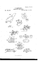
- a two-part die consisting of sections A B, detached views of which are shown on Plates 4 and 5, and which, when the two sections are closed, as shown in Fig. 15, (an under-side view of the die,) is in its contour the shape of a horseshoe.
- Said die opens and closes laterally by means of a pair of slides, O D, in whieh are slots 0.
- In each of said slots is a pin, f, projeeting downward from the hottom of each of the sections A B of the die.
- the means for actuating the slides for opening and closing the die Will hereinafter be shown.
- a reciprocating movement is given to the bed earrying the die by the following devices:
- a segmental lever, E In the lower end of the honsings B referred to is journaled a segmental lever, E, Figs. 1 and 2, detached views of whieh are shown in Figs. (land 7, also in Fig. 18, in which it will be seen that said lever consists of two arme, constitnting a pair of levers, in each of which is a slot, 9, wherein is fitted sliding boxes F, the journal seats of the wrists G of the eranks H, Figs. 6 and 7.
- cranks have their bearings in hangers depending from the sides of the frame A, and to which said shaits are secured the cogwheels J respectively, and wherehy the cranks are' actuated for opeiating the lever or levers E.
- the upward arms of the lever are segments et gear J, which are made to engage corresponding raoks K, Figs. 6 and 7, on the under side of the carriage or bed of the die, or
- L is an arm,the 10W- er end of Which is secured to the shaft M between the levers as will be seen in Fig. 18.
- the upper end of said arrn terminates in a head, N, and whereon the bedor carriage W et the die reste, said bed and die being mainly its iulcrum in the stay S.
- Fig. 1 is fittod a carriage, I), wherein is pivoted a barrel, 0.
- a stem d, on the end of which is fixed a head, 6.
- a die or former f, the contour of which is the shape of the inside of a horseshoe.
- the edge of the head projects beyond the edge ofthe die, thereby forming a shoulder above the sides or edge of the die or former.
- Said hook is the termination of a pendent vibratory arm, h, suspended from and piv' oted in the end of an ami, q, as shown in Figs. 1, 11, and 13.
- Said pendent arm is pushed forward to its position (shown in Fig. 13) by a spring, h, and rod 70, applied thereto, as shown in the drawing.
- B is a lever, having From the front end of said lever projeots downward through a notch in the head 6 a pin, T; also, from each side of the end of the lever depends a pin, 72. Said pin passes through thesides ofthe head to the edge of the die or former, as will be seen in Fig. 13. The purpose of said pins T and i Will hereinalter be shown.
- Tl1e outer end of said lever B is elevated by a spring, U, thereby depressing the front end and Causing a depression of the pins in the head.
- Said head is depressed by the vibration of the stem d, operated by an arm, V, which, in turn, is operated by the pin M, projecting from the wheel K, Fig. 3, above referred to.
- the upward movement of the head is caused by the reaction of the spring N, Fig. l.
- a pair of arms, y y On the shaft .90, Fig. 3, is secured a pair of arms, y y. Said arms are actuated, for a purpose hereinafter shown, by an arm, 7c, attached to the shatt bearing the arms, and extending therefrom to the wheel K, whereby it is operated by the pin L, above alluded to.
- Figs. l, 2, and 3 is such' as when a piece of iron for a shoe has just been ont off from a bar, and is about to be embraced by the die for bending, the cutting alluded to (which immediately prccedes the arrival of the pressing-die 71. to the position shown in the drawing) is done by the shear R, the blade of which is raised, as shown in Fig. 9, and a bar of iron is pushed under it and across the machine in front of the lower die t0 a gage, as indicated by the dotted lines h, Fig. 3. The blade of the shear is forced down by the pin 15, Figs. 1
- the blank is bent in around the sides of the former to form the heel of the shoe by the closing together of the die.
- This olosing of the die is eflected by the ends ac, Figs. 3 and 5, of the slides C D impinging upon the end otthe trame A at m, Fig. 3.
- the die closes by the influence of the slots and pins shown in Fig. 16, to the closed state shown in Fig.
- theblank is forced around the sides of the former under the projection of the head;
- the pins T and e i push the shoe from offthe former, leaving it inclosed in the female or lower die, for being further operated upon by the intermittent revolving dies t n.
- said former and the head are depressed from their raised position (shown in Fig. 1) to the horizontal position. (Shown in Figs. 11 and 13.)
- This depressing of the head and former is done by the arm V, which at the proper time in the revolution of the wheel K is impinged upon by the pin M, which, as above shown, operates the stem d for that purpose.
- the said carriage is thereby pushed back so far as to ca use the pin M t0 slip from the end ofthe arm on which it Will be seen in Fig. 3 to pushed trom under the shoe by its contact With a pin, 6', Fig. 16, in the toe of the di against which it cornes in contact, in proper time, in the course of the forward movement of the die, said movement being in the direction of the arrow in Fig. 3.
- This movable' character of the carriage b prevents undue strain upon the die, should there be any diflerence in the thickness of the blanks, or the degrecs of heat of the same.
- the carriage may be adjusted to various widths or thickness of iron for large or small sh'oes by shortening up, or by extending, the rod a, which is so connected to the carriage by adjnsting-nuts as to adapt it for that purpose.
- the die when closed around the shoe is prevented from opening, While the shoe therein is being operated upon, by means of the studs or p1nsf, which at this time are in the slots e et the slides C D, as shown in Fig. 15, thereby eftectually locking the dies as well as closing them.
- the die now closed around the shoe and locked, and the hook g and the former removed therefrom, as shown in Fig.
- the die begins to retnrn by the now downward action of the lever or levers E to meet and receive the pressing-die n, Fig. 3, held in the head D, detached views of which are shown in Plate 5.
- the head Dis made to revolve, for bringing the die n into the lower die or shoe-die, holding the shoe by the engagement of the segment Gr With the rack F, Figs. 3, 5, and 10, secured to the die-bed or carriage.
- the position of the segment in respect to the rack at the time the lower die begins to move back is such that it will not engage the rack, it not being turned far enougb around to engage it at that instant, as Will be seen in Fig.
- the lower die having. by this time been pushed forward to the return-point, it is again n10ved back by the downward movement of the levers E and segment J, as before described.
- the head D revolves, thereby bringiug the creasing-die tint-o co-relation with the lower die, and which continues to revolve while the die is passing underit, therehy creasing and marking the mail-prints in the face ofthe.shoe by a rolling pressing action.
- the removal of the shoe from the die is effected as follows During the rearward movement of the die following the action of the .creasing-die the arms y y, Fig. 3, are elevated from a horizontal position to that shown in Fig. 8, by means of the arm 7c, engaging, at the proper time during the movements of the machine) the pin L. This elevation of the arms causes them to engage the ends of the slides C D during the rearward movement of the die-bed. Said slides by this contact with the arms are pushed in, thereby opening the die, as shown in Fig. 16.
- the die thus o'pened allows the end of the bar 0, Figs. 3 and 1, t0 spring forward between them and force the shoe from the die before the return of the diehed.
- the die remains open to receive the bar or blank awaiting its return to be Dent therein and hy around the former f, suhstantially in the same way as hereinbefore described, the operation of the machine being again wholly repeated.
- the position of the sliding boxes, as shown in Fig. 6, is such as when the dies are not in conjunctive relation. Henoe the weight of the die-bed and die is all that the lever or levers E have to move, now, at their shortest leverage.
- the die bed or carriage now moves baok, and when at a certain point in its backward movement the revolving die -n enters the lower or bed die, and presses the bevel on the shoe held therein, the rotation of the die 12 being efiected by the segment G and rack F.
- This pressing having been done, the lower die returns to the front, from whence it started, and from which it is again moved rearward by the segments J and rack K.
- the upper die t engages the lower die, and by a revolving pressingaction creases and forms the prints for the nail-holes in the face of the shoe.
- the shoe on passing from under the upper die, is ejected from the die by the rod 0, which enters between the open die and forces the shoe therefrom, the die being opened for the release of the shoe by the slides C D in their contact with the arms y 3 at this time elevated that they may engage the ends of the slide for the purpose aforesaid.
- the now empty die returns again to the front, and is closed by the contact et the ends of the slides With the end of the frame, thereby bonding a blank around the formerf, previously out from the bar, as above described, and which, in the same manner, is subjected to the action of the revolving dies, substantially as set forth, the various operations and movements of the machine all being timely and in order, for the accomplishmeut of the purposes described.
- lever or levers E having 3. segmental arm or arms, J, in comhination with the cranks H H, and die bed or carriage W for operating the same, substantially as hercin deseribed, andfor the purpose set forth.
- the intermittent revolving die-head D having thereon (lies t and n, in combination 'With the reciprooating bed-die consisting of sections A B, slides O D, and devices for arresting the forward and baokward movements of the slides, substantially in the manner as deseribed, and for the purpose spacified.
- Arm or lever K, and arms y y arranged to operate in combination with the wheel K and pin L, substantially as described, and for the purpose speeified.
- the pendent vibratory arm h having a book, g, spring 72/, and rod 70, in combination With the head 6, and die or former f, in the manner substantially as described, and for the purpose set forth.
Landscapes
- Forging (AREA)
Description
5 Sheets-Sheet 1.
M. BENJAMIN. HORSESHOE MACHINE.
Patented Dec. 12, 1876.
N.PEERS, FHOTO-LITHOCRAFNEL WASHINGTON. D (:4
5 Shets-Sheet z.
' M. BENJAMIN.
en 7 8 1- 2 1 c e D d 9 ch n .8 Et a ..P. c A M E 0 H, S E S R 0 H M. BENJAMIN.-
' HORSESHOE MACHINE. No.185,161. Patented Dec.12,'1876.
5 Sheets-Sheet 5 N,PEERS. PNOTO|JTHDGRPHER. WASHINGTON. D. C.
UNITED STATES PATENT OFFICE.
MYRON BENJAMIN, OF CLEVELAND, 0H10, ASSIGNOR TO SAMUEL M. CARPENTER AND WILLIAM F. SMITH, OF SAME PLACE.
IMPROVEMENT IN HORSESHOE-MACHINES.
Specification forming part of Letters Patent No. 185,161, dated December 12, 1876; application filed September 18, 1876.
T0 all whom z't may concern Be it kn0Wn that I, MYRON BENJAMIN, of
Oleveland, in the connty of (luyahoga and State of Ohio, have invented new and nseful Improvements in Horseshoe -Maohines, of which the following is a description, reterence hein g had to the accompanying drawings, making a part of this specification, in which Figure 1 is a side elevation of the machine; Fig. 2, an end elevation, and Fig. 3, a plan vxew.
The rest of the views presexited are detached sections, to which reference Will he made.
Like letters of reference refer to like parts in the several views.
The nature of this invention relates to 3 machine for making horseshoes, of which the following is a detailed description of the con struction and operation of the same.
To each side of a frame A is securcd a honsing, B, Fig. 2, the upper end of which aftords bearings for the trunnions or shaft O, carrying a die-head, D, Fig. 3. A iurther description of the head and dies will hereinafter he made. On said shait 0 is seonred a wheel, E, Figs. 2 and 3, to the side of which is seonred, in an adjnstable manner, segments et gear F G, a detaohed view of which is shown in Figs. 6 and 7, Plate 4. To each of the segments is attached au arm, H. The purpose of said segments and arms will presently he shown. On (me end of the shaf't 0 is seonred a wheel, 1, Fig. 1, in the two opposite sides of which is a notch, J, shown also in the detached views, Figs. 4 and 9. On the opposite end of the shalt is secnred a wheel, K, Figs. 2 and 3, from the outer side of which projects a pin, L, and from the inner side a pin, M, Fig. 3. To the honsing B, directly under the wheel 1, is attached a sleeve, N, Fig. 1, in which is litted a slide, 0, in the head of which is a roller, a, Fig. 2, of a size to engage the notches J referred to, and which is forced upward therein, and npon the periphery of the wheel upon whioh it rnns, by a spring inclosed in thev sleeve N aronnd the slide for that pnrpose. P, Figs. 1 and 2, is a slide attaohed to one et the honsings B by screws b inserted in slots g, which permit the movement of the slide. Directly in front of the sections thereof, A B.
wheel I is a shear, R, operated by an arm, S, secnred to the shaft T, carrying the shear. Said shaft has its bearings in a stay, U, Fig. 3. Within the frame A, npon the ledges V, is a carriage or bed, WV, Figs. 2, 3, and 6,
'whereon is arranged a two-part die, consisting of sections A B, detached views of which are shown on Plates 4 and 5, and which, when the two sections are closed, as shown in Fig. 15, (an under-side view of the die,) is in its contour the shape of a horseshoe. Said die opens and closes laterally by means of a pair of slides, O D, in whieh are slots 0. In each of said slots is a pin, f, projeeting downward from the hottom of each of the sections A B of the die. Hence, as the slides are moved longitudinally the sections are moved thereby laterally, for opening and closing the die, as shown in Plate 5, in which Fig. 15 shows the die as closed, and Fig. 16 as when open.
The means for actuating the slides for opening and closing the die Will hereinafter be shown.
A reciprocating movement is given to the bed earrying the die by the following devices: In the lower end of the honsings B referred to is journaled a segmental lever, E, Figs. 1 and 2, detached views of whieh are shown in Figs. (land 7, also in Fig. 18, in which it will be seen that said lever consists of two arme, constitnting a pair of levers, in each of which is a slot, 9, wherein is fitted sliding boxes F, the journal seats of the wrists G of the eranks H, Figs. 6 and 7. The shatts I of said cranks have their bearings in hangers depending from the sides of the frame A, and to which said shaits are secured the cogwheels J respectively, and wherehy the cranks are' actuated for opeiating the lever or levers E.
The upward arms of the lever are segments et gear J, which are made to engage corresponding raoks K, Figs. 6 and 7, on the under side of the carriage or bed of the die, or
L is an arm,the 10W- er end of Which is secured to the shaft M between the levers as will be seen in Fig. 18. The upper end of said arrn terminates in a head, N, and whereon the bedor carriage W et the die reste, said bed and die being mainly its iulcrum in the stay S.
supported thereby and partially by the ledges V referred to, they being in part guides for the reciprocating movement of the aforesaid bed and die, and Which also prevent said bed from lifting up, it being secured to the nnder side of the guides by gibs. 0 is a bar, held loosely in a sleeve, 1?, and which is moved forward toward the die by the reooil of a s ')ring inclosed in the sleeve. The purpose of the aforesaid bar will presently be shown. On the ways a, Fig. 1, is fittod a carriage, I), wherein is pivoted a barrel, 0. In said harrel is secured a stem, d, on the end of which is fixed a head, 6. To the under side of said head is attached a die or former, f, the contour of which is the shape of the inside of a horseshoe. The edge of the head, as will be seen, projects beyond the edge ofthe die, thereby forming a shoulder above the sides or edge of the die or former. From the front end of said former projeots a hook, g, Figs. 11 and 13. Said hook is the termination of a pendent vibratory arm, h, suspended from and piv' oted in the end of an ami, q, as shown in Figs. 1, 11, and 13. Said pendent arm is pushed forward to its position (shown in Fig. 13) by a spring, h, and rod 70, applied thereto, as shown in the drawing. B is a lever, having From the front end of said lever projeots downward through a notch in the head 6 a pin, T; also, from each side of the end of the lever depends a pin, 72. Said pin passes through thesides ofthe head to the edge of the die or former, as will be seen in Fig. 13. The purpose of said pins T and i Will hereinalter be shown. Tl1e outer end of said lever B is elevated by a spring, U, thereby depressing the front end and Causing a depression of the pins in the head. Said head is depressed by the vibration of the stem d, operated by an arm, V, which, in turn, is operated by the pin M, projecting from the wheel K, Fig. 3, above referred to. The upward movement of the head is caused by the reaction of the spring N, Fig. l.
On the shaft .90, Fig. 3, is secured a pair of arms, y y. Said arms are actuated, for a purpose hereinafter shown, by an arm, 7c, attached to the shatt bearing the arms, and extending therefrom to the wheel K, whereby it is operated by the pin L, above alluded to.
Having described the construction of the machine, We will now proceed to describe the operation of the same, Which is substantially as follows: The position ot the machine, as
.shown in Figs. l, 2, and 3, is such' as when a piece of iron for a shoe has just been ont off from a bar, and is about to be embraced by the die for bending, the cutting alluded to (which immediately prccedes the arrival of the pressing-die 71. to the position shown in the drawing) is done by the shear R, the blade of which is raised, as shown in Fig. 9, and a bar of iron is pushed under it and across the machine in front of the lower die t0 a gage, as indicated by the dotted lines h, Fig. 3. The blade of the shear is forced down by the pin 15, Figs. 1
and 9, which, at the proper mime, comes in contact with the arm S during the revolution of the wheel I. The piece for the shoe, on being out from the bar, lies, as above said, in front of the lower die, between the hook 9 and the head 6. The lower die, now open, is moved forward by the forward movement of the bed, operated by the segments J J of the lever or levers E, in their engagement with the racks K K. This forward movement of the die bonds the iron (termed a blank) around the toe of the die or formerf, -under the projection of the head 6, and by which the banding-blank is pievented from sprin gin g upward, and by the hook g is prevented from bending downward or rolling over.
The blank is bent in around the sides of the former to form the heel of the shoe by the closing together of the die. This olosing of the die is eflected by the ends ac, Figs. 3 and 5, of the slides C D impinging upon the end otthe trame A at m, Fig. 3. As the die closes, by the influence of the slots and pins shown in Fig. 16, to the closed state shown in Fig.
15, theblank is forced around the sides of the former under the projection of the head; The pins T and e i push the shoe from offthe former, leaving it inclosed in the female or lower die, for being further operated upon by the intermittent revolving dies t n. Immediately preceding the engagement of the former with the blank, said former and the head are depressed from their raised position (shown in Fig. 1) to the horizontal position. (Shown in Figs. 11 and 13.) This depressing of the head and former is done by the arm V, which at the proper time in the revolution of the wheel K is impinged upon by the pin M, which, as above shown, operates the stem d for that purpose. This depression of the head brings the former in horizontal relation to the lower die, in order that the blank may enter therein properly. While the blank is being bent aronnd the toe of the former, and lorced into the open die, that it may be closed thereby against the sides of the former for shaping the heel of the shoe, the head and former romain 'held down to the die by the arm V, which, as
yet, continues its engagement with the depressing-pin M of the wheel K, said wheel at this time remaining still, together with the head D, carrying the dies t nthat is to say,
during the bending of the blank about the toc of the former, and the closing in of the die by its continued forward movement. In order that the die inclosing the shoe (now bent about the former) may return, the former must first be removed from the shoe. This is effected b}; disengaging the arm V from the pin M by means of the bed or oarriage of the die. Thus, as the carriage or bed continues its forward movement while the blank in the die is bending, the end of the bed impinges upon the end of a rod, (indicated by the dotted limes a, Fig. 1,) said rod hein g attached to the carriage I). The said carriage is thereby pushed back so far as to ca use the pin M t0 slip from the end ofthe arm on which it Will be seen in Fig. 3 to pushed trom under the shoe by its contact With a pin, 6', Fig. 16, in the toe of the di against which it cornes in contact, in proper time, in the course of the forward movement of the die, said movement being in the direction of the arrow in Fig. 3. This movable' character of the carriage b prevents undue strain upon the die, should there be any diflerence in the thickness of the blanks, or the degrecs of heat of the same.
The carriage may be adjusted to various widths or thickness of iron for large or small sh'oes by shortening up, or by extending, the rod a, which is so connected to the carriage by adjnsting-nuts as to adapt it for that purpose.
The die when closed around the shoe is prevented from opening, While the shoe therein is being operated upon, by means of the studs or p1nsf, which at this time are in the slots e et the slides C D, as shown in Fig. 15, thereby eftectually locking the dies as well as closing them. The die now closed around the shoe and locked, and the hook g and the former removed therefrom, as shown in Fig.
. 11, the die begins to retnrn by the now downward action of the lever or levers E to meet and receive the pressing-die n, Fig. 3, held in the head D, detached views of which are shown in Plate 5. The head Dis made to revolve, for bringing the die n into the lower die or shoe-die, holding the shoe by the engagement of the segment Gr With the rack F, Figs. 3, 5, and 10, secured to the die-bed or carriage. The position of the segment in respect to the rack at the time the lower die begins to move back is such that it will not engage the rack, it not being turned far enougb around to engage it at that instant, as Will be seen in Fig. 1,,the segment and revolving head being retained in this position by the slide O, lodged in one of the notches J of the wheel I. At the proper time in the rearward movement of ,the die the segment is made to engage the rack F by means of the Spring j, Figs. 3, 6, and 10, attached to one side of the die-bed, close to the side of the 'rack, as shown in Fig. 5, in which it will be seen that the free end of the spring projects beyond the edge of the bed, and hence in advance et the end of the rack, At the proper moment, as the bed moves back, the end of the spring Will engage the hook H, attached to the segment, in advance ot the rack, and
so far turn the segment as to cause li? to engage the rack, as seen in Fig. 10, in time for the head D t0 revolve and bring the die -n down upon the shoe in the lower die. As the bed continues to move back, the upper die n continues to revolve, thereby rolling upon and pressing the shoe in the die, and forming on the shoe the bevel on the inner side thereof. This rearward movement of the die-bed goes so far as the segnlent J of the levers E will carry the bed, and during which movement the die will have performed its duty in pressing the shoe, and at Which time the head and die have ceased to rotate, the segment Gr hav:
ing traversed the rack F, by Which it was revolved, and is now, therefore, disengaged therefrom, With the pressing-die raised above the lower one, so that said lower die may pass under it' in its return to the front end of the machine, from whence it started. This again forward movement of the die-bed is effected hy the npward action of the lever or le"ers E from the position shown in Fig. 6, which represents the die-bed as having passed under the revolving die and about to return to the front, as shown in Fig. 1. While the bed-die is returning to the front the upper dies are continued in their reVolution by the vertical slide P, Fig. 1, which, by the timely movement of the wheel J, brings the pin m to the arm 0, as shown in Fig. 4, thereby pushing upward said slide, causing it to engage a pin, 1, Fig. 2, whereby the wheel I is so far rotated as to revolve the head and bring the creasing-die t to the front, thus revrsing the position of'the head D, (shown in Fig. 3,) the die t being by this movement where the die n is shown to be in said Fig. 3. When the revolving dies have obtained this position, the slide P drops down, the pin m having become disengaged from the arm c ofthe slide. This position of the head D is maintained for a short time by the slide 0, Fig. 1, being pushed upward by a spring in the sleeve N into one of the notches J, which at this time is presented to the slide. The creasing-die is now in position to engage the lower die for creasing and marking the prints in the shoe for the nail-holes, and partially punching the same.
The lower die having. by this time been pushed forward to the return-point, it is again n10ved back by the downward movement of the levers E and segment J, as before described. At an opportune moment in the rearward movement of the die-bed the head D revolves, thereby bringiug the creasing-die tint-o co-relation with the lower die, and which continues to revolve while the die is passing underit, therehy creasing and marking the mail-prints in the face ofthe.shoe by a rolling pressing action.
The revolving movement of the head and die alluded to is accomplished by the segment F engaging the rack F. The engagement of the two is etected by substantially the same means employed to engage them for the operation of the die n, viz., the springj and a hook, H, each segment being alike furnished with a hook, as Will be seen in Fig. 6, which, in their opportune co-operation with the. spring j,
causes a timely engagement of the segment With the raclc F, to produce a concertation of action of the revolving dies with the lower one for pressing the bevel on the inside of the shoe, and creasing and marking the mailprints in the face thereof. The creasing-die having performed its duty on the shoe, the shoe is now to he removed from the die, to give place to another blank, which, by this time, has been placed in position by inserting a bar under the shear R, by which the blank is to be ont off, which, during the several movements of the machine, has been operated in due time for that purpose.
The removal of the shoe from the die is effected as follows During the rearward movement of the die following the action of the .creasing-die the arms y y, Fig. 3, are elevated from a horizontal position to that shown in Fig. 8, by means of the arm 7c, engaging, at the proper time during the movements of the machine) the pin L. This elevation of the arms causes them to engage the ends of the slides C D during the rearward movement of the die-bed. Said slides by this contact with the arms are pushed in, thereby opening the die, as shown in Fig. 16. The die thus o'pened allows the end of the bar 0, Figs. 3 and 1, t0 spring forward between them and force the shoe from the die before the return of the diehed. The die remains open to receive the bar or blank awaiting its return to be Dent therein and hy around the former f, suhstantially in the same way as hereinbefore described, the operation of the machine being again wholly repeated.
It will be observed that the greatest efficient power of the lever or levers E is dnring the time that the revolving dies and the beddie are, respectively, in conjunction, in Which event the sliding boxes F of the cranks H are nearest the end of the levers, as will be seen in Fig. 7, also in Fig. 18. The power thus applied to the end of the levers overeomes the increased resistance of the bed to move, caused hy the increased pressure of the dies on the shoe being operated thereby.
The position of the sliding boxes, as shown in Fig. 6, is such as when the dies are not in conjunctive relation. Henoe the weight of the die-bed and die is all that the lever or levers E have to move, now, at their shortest leverage.
In the course of the movement of the machine, as the dies oome together, pressing the shoe, their resistance to be moved is increased, at which ti me or times the lever-power is also increased by the ontward movement of the sliding boxes toward the end et the lever. Therc1ore, a proportionate, steady, and efficient power is applied for operating the machine.
The peculiar construction of the levers E is suchas to cause a much quicker forward movoment than a rearward one of the die-bed or carriage; hence the dies are brought sooner into operative relation than if the reciprocatin g movement of the bed were performed in the same length of time. Therefore is increased the productive capacity of the machine.
A resume of the general movements of the machine is thns: At au opportune moment in the course of the operation of the machine the end of a bar of iron is pushed under the shear, across the machine, to a gage. By the shear a proper length for a shoe is out off, and which now lies in front of the head 6, between it and the lower die, which now moves forward open to receive it. This movement of the die bends the blank around the toe of the former f and against the sides of which it is now pressed by the closing together of the die, the die being carried forward by the levers E, and closed by the slides O D. The die bed or carriage now moves baok, and when at a certain point in its backward movement the revolving die -n enters the lower or bed die, and presses the bevel on the shoe held therein, the rotation of the die 12 being efiected by the segment G and rack F. This pressing having been done, the lower die returns to the front, from whence it started, and from which it is again moved rearward by the segments J and rack K. At a certain point in the rearward movement of the die-bed the upper die t engages the lower die, and by a revolving pressingaction creases and forms the prints for the nail-holes in the face of the shoe. The shoe, on passing from under the upper die, is ejected from the die by the rod 0, which enters between the open die and forces the shoe therefrom, the die being opened for the release of the shoe by the slides C D in their contact with the arms y 3 at this time elevated that they may engage the ends of the slide for the purpose aforesaid. The now empty die returns again to the front, and is closed by the contact et the ends of the slides With the end of the frame, thereby bonding a blank around the formerf, previously out from the bar, as above described, and which, in the same manner, is subjected to the action of the revolving dies, substantially as set forth, the various operations and movements of the machine all being timely and in order, for the accomplishmeut of the purposes described. v
What I claim as my invention, and desire to secure by Letters Patent, is
1. The lever or levers E, having 3. segmental arm or arms, J, in comhination with the cranks H H, and die bed or carriage W for operating the same, substantially as hercin deseribed, andfor the purpose set forth.
. 2. The segments F G and hooks H H, arranged to operate in combination With the rack F and springj, in the manner substantially as described, and for the purpose specified.
3. The intermittent revolving die-head D, having thereon (lies t and n, in combination 'With the reciprooating bed-die consisting of sections A B, slides O D, and devices for arresting the forward and baokward movements of the slides, substantially in the manner as deseribed, and for the purpose spacified.
4. The intermittingly-revolvin g diehead D, having thereon dies 15 and H, in combination with the notched wheel I, slide O. barrel N, and spring therein, pin 1, and slide P, substantially in the manner as described, and for the purpose set forth.
5. In combination With the stay-wheel land pin 1, the vertical slide P, and wrist-pin m of the wheel J, operating snbstantially as described, and for the purpose set forth.
6. Arm or lever K, and arms y y, arranged to operate in combination with the wheel K and pin L, substantially as described, and for the purpose speeified.
7. In combination With the vibratory arm or Stem d, the arm V, wheel K, pin M, and spring w, substantially as and for the pnrpose set fo'rth.
8. The lever B, pin T, pins z 2', and spring U, arranged t0 operace in combination With the head 6 and die or former f, substantially as described, and for the purpose specified.
9. The pendent vibratory arm h, having a book, g, spring 72/, and rod 70, in combination With the head 6, and die or former f, in the manner substantially as described, and for the purpose set forth.
10. 'lhe combination of the sliding carriage b, spring w, and vibratory stem or arm MYRON BENJAMIN.
Witnesses J. H. BURRIDGE, R. SIMPSON.
Publications (1)
| Publication Number | Publication Date |
|---|---|
| US185161A true US185161A (en) | 1876-12-12 |
Family
ID=2254566
Family Applications (1)
| Application Number | Title | Priority Date | Filing Date |
|---|---|---|---|
| US185161D Expired - Lifetime US185161A (en) | Improvement in horseshoe-machines |
Country Status (1)
| Country | Link |
|---|---|
| US (1) | US185161A (en) |
Cited By (2)
| Publication number | Priority date | Publication date | Assignee | Title |
|---|---|---|---|---|
| US20050265350A1 (en) * | 2004-05-28 | 2005-12-01 | Murali Narasimha | Concurrent packet data session set-up for push-to-talk over cellular |
| US20060056381A1 (en) * | 2004-08-25 | 2006-03-16 | Samsung Electronics Co., Ltd. | Mobile communication system and packet processing method thereof |
-
0
- US US185161D patent/US185161A/en not_active Expired - Lifetime
Cited By (2)
| Publication number | Priority date | Publication date | Assignee | Title |
|---|---|---|---|---|
| US20050265350A1 (en) * | 2004-05-28 | 2005-12-01 | Murali Narasimha | Concurrent packet data session set-up for push-to-talk over cellular |
| US20060056381A1 (en) * | 2004-08-25 | 2006-03-16 | Samsung Electronics Co., Ltd. | Mobile communication system and packet processing method thereof |
Similar Documents
| Publication | Publication Date | Title |
|---|---|---|
| US185161A (en) | Improvement in horseshoe-machines | |
| US321542A (en) | sheppard | |
| US87046A (en) | Improved machine for making nuts | |
| US252440A (en) | Bolt-heading machine | |
| US305165A (en) | John h | |
| US184436A (en) | Improvement in machines for heading wrench-bars | |
| US53782A (en) | Improvement in nut-machines | |
| US6160A (en) | Spike-machine | |
| US390118A (en) | Machine | |
| US787128A (en) | Ladder-handle-forming machine. | |
| US189322A (en) | Improvement in horseshoe-machines | |
| US96762A (en) | Improved horseshoe-machine | |
| US36041A (en) | Improvement in machines for making horseshoes | |
| US316073A (en) | Leather-cutting press | |
| US651748A (en) | Spiral-die. | |
| US68556A (en) | burdiot | |
| US195845A (en) | Improvement in apparatus for forming heel-counters for boots and shoes | |
| US148754A (en) | Improvement in bolt-heading machines | |
| US119051A (en) | Improvement in machines for making horseshoes | |
| US170931A (en) | Improvement in horseshoe-machines | |
| US240538A (en) | powers | |
| US575790A (en) | Forcing-machine | |
| US105030A (en) | Improved heel-press | |
| US114068A (en) | Improvement in machines for punching and stamping metal | |
| US157713A (en) | Improvement in machines for pointing horseshoe-nails |