US1851612A - Doorstop - Google Patents
Doorstop Download PDFInfo
- Publication number
- US1851612A US1851612A US7726525A US1851612A US 1851612 A US1851612 A US 1851612A US 7726525 A US7726525 A US 7726525A US 1851612 A US1851612 A US 1851612A
- Authority
- US
- United States
- Prior art keywords
- arm
- door
- catch
- support
- movement
- Prior art date
- Legal status (The legal status is an assumption and is not a legal conclusion. Google has not performed a legal analysis and makes no representation as to the accuracy of the status listed.)
- Expired - Lifetime
Links
- 230000004075 alteration Effects 0.000 description 1
- 239000011324 bead Substances 0.000 description 1
- 238000005266 casting Methods 0.000 description 1
- 230000005484 gravity Effects 0.000 description 1
- 238000003754 machining Methods 0.000 description 1
- 238000004519 manufacturing process Methods 0.000 description 1
- 238000000034 method Methods 0.000 description 1
- 238000012986 modification Methods 0.000 description 1
- 230000004048 modification Effects 0.000 description 1
- 238000000926 separation method Methods 0.000 description 1
Images
Classifications
-
- E—FIXED CONSTRUCTIONS
- E05—LOCKS; KEYS; WINDOW OR DOOR FITTINGS; SAFES
- E05C—BOLTS OR FASTENING DEVICES FOR WINGS, SPECIALLY FOR DOORS OR WINDOWS
- E05C17/00—Devices for holding wings open; Devices for limiting opening of wings or for holding wings open by a movable member extending between frame and wing; Braking devices, stops or buffers, combined therewith
- E05C17/02—Devices for holding wings open; Devices for limiting opening of wings or for holding wings open by a movable member extending between frame and wing; Braking devices, stops or buffers, combined therewith by mechanical means
- E05C17/44—Devices for holding wings open; Devices for limiting opening of wings or for holding wings open by a movable member extending between frame and wing; Braking devices, stops or buffers, combined therewith by mechanical means with a device carried on the wing for frictional or like engagement with a fixed flat surface, e.g. for holding wings open or closed by retractable feet
- E05C17/443—Devices for holding wings open; Devices for limiting opening of wings or for holding wings open by a movable member extending between frame and wing; Braking devices, stops or buffers, combined therewith by mechanical means with a device carried on the wing for frictional or like engagement with a fixed flat surface, e.g. for holding wings open or closed by retractable feet of the pivoted lever or eccentric type, e.g. for sliding windows
-
- Y—GENERAL TAGGING OF NEW TECHNOLOGICAL DEVELOPMENTS; GENERAL TAGGING OF CROSS-SECTIONAL TECHNOLOGIES SPANNING OVER SEVERAL SECTIONS OF THE IPC; TECHNICAL SUBJECTS COVERED BY FORMER USPC CROSS-REFERENCE ART COLLECTIONS [XRACs] AND DIGESTS
- Y10—TECHNICAL SUBJECTS COVERED BY FORMER USPC
- Y10S—TECHNICAL SUBJECTS COVERED BY FORMER USPC CROSS-REFERENCE ART COLLECTIONS [XRACs] AND DIGESTS
- Y10S292/00—Closure fasteners
- Y10S292/15—Door, checks, floor
-
- Y—GENERAL TAGGING OF NEW TECHNOLOGICAL DEVELOPMENTS; GENERAL TAGGING OF CROSS-SECTIONAL TECHNOLOGIES SPANNING OVER SEVERAL SECTIONS OF THE IPC; TECHNICAL SUBJECTS COVERED BY FORMER USPC CROSS-REFERENCE ART COLLECTIONS [XRACs] AND DIGESTS
- Y10—TECHNICAL SUBJECTS COVERED BY FORMER USPC
- Y10T—TECHNICAL SUBJECTS COVERED BY FORMER US CLASSIFICATION
- Y10T292/00—Closure fasteners
- Y10T292/65—Braces
Definitions
- My invention relates to d'oor stops, and morespecifical-ly to-an improvement in the type of door stop, comprising a pivoted stop member adapted to-drag over the floor as ethe door is moved in one direction-and grip the floor frictionally to prevent return movement;
- Figure 1 is a section of the device according to the invention on line 1-1 of Figure 3;
- Figure 2 is a side elevation of the parts with the arm approaching operative position' 8:
- Figure 3 is a similar view with the arm swung up into inoperative position;
- Figure 4 is a section of the support on line 4-4 of Figure 1;
- FIGS. 5 and 6 are detail sectional views, 46 indicating the method of fastening the catch means in place. V
- the support comprises a face plate 10 apertured at 12 for attachv ment to a door, or the like, and an arm 14 pivoted thereon for movement down into the operative positionof Figure 2, or up into the inoperative position of Flgure 3.
- the support is a face plate 10 apertured at 12 for attachv ment to a door, or the like, and an arm 14 pivoted thereon for movement down into the operative positionof Figure 2, or up into the inoperative position of Flgure 3.
- thearm 14 is thepentral member-of the pivot, and itstubular walliispreferably flared out from an mal 9 38 of rubber, or the like;
- the attachment means for this rubber-foot comprises a simple screw thread formed inside thelarm 14 atithe end.
- the threads 40 will imbed themselves in the shank 42 and form an entirely satisfactory retaining means.
- a door stop comprising a U-shaped support; an arm having one end pivoted between the leaves of said support; a laterally movement about an axis parallel to the face of the door; and catch means operating par allel to the axis of rotation for holding said arm swung upvbeside the door, said catch 'means'comprising a spring pressed projec-,
- socket means provided with'a circumferential recess for receiving said projection, out of contact therewitl1,'wl1en said armis in operative position, and with another recess latchingly engaging said projection when the arm is in inoperative position.
- a door stop comprising a member adapted to be secured to a door, a movable member flexibly connected to said first memher, a spring pressed catchmember carried by one of said members and adapted to project-vtherefrom,vmeans on the other of said members for engaging with saidcatch 111cm- 7 her when said flexibly connected member is in an inoperative position, and a circumferentially elongated recess in said other member for receiving said catch member to leave said movable member freely movable When in operative position.
- a door stop comprising: a support, in-
- a plate adapted to be bolted to the face of a door, and spaced members projecting from said plate away'from the door; a pintle, having an axis parallel to the face of the door, and supported by said spaced members; an arm, having a head housed between saidcspaced members and pivoted on said pintle, said head lying close to said plate to secure minimum dimensions perpendicular to the door;-and a spring pressed ball catch housed in the head of said arm, within the extent of and between said members; said support being provided with a socket for latchingly receiving said ball catch when said armis in elevated position, and being formed to permit free swinging of said arm through the normal range of movement of said arm, up to elevated position; v
Landscapes
- Engineering & Computer Science (AREA)
- Mechanical Engineering (AREA)
- Hinges (AREA)
Description
March 29, 1932. A. c. WERTH I 1,851,612
DOORSTOP Original Filed D60. 23, 1925 fired 6 Wei/z,
ATTORNEYS.
Patented Mar. 29 1932 ALFRED-G. wnnmngmn LA.PIORTE; mmn-neg-nssrenoaro unvmlrr. aonnson or 7-? LA TORTE, INDIAN-A noons'ron Application fi1edJDecember'23,'1925, Serial No. 77,265. Re ewed March 14, 1930. 3
My invention relates to d'oor stops, and morespecifical-ly to-an improvement in the type of door stop, comprising a pivoted stop member adapted to-drag over the floor as ethe door is moved in one direction-and grip the floor frictionally to prevent return movement;
Among the objects and advantages of the inventionmay be enumerated First, the operating characteristic of hav-' ing the arm very loosely pivoted when in operativeposition to maintaingood with the floor, and grip promptly at the beginning of return movement;
Second, a characteristic relating to durability in service, involving the subjection of the catch means for holding the arm in in operative position, to a minimum of wear; and
to Third, characteristics relating to cheapness and convenience in manufacture such as the employment of an extremely simple shape for the friction terminal, and forming the two main elements of simple shapes, suitable for casting at small expense.
Other objects and advantages of the invention will become apparent as the description proceeds.
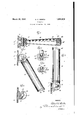
In the accompanying drawings: 80 Figure 1 is a section of the device according to the invention on line 1-1 of Figure 3; Figure 2 is a side elevation of the parts with the arm approaching operative position' 8: Figure 3 is a similar view with the arm swung up into inoperative position;
Figure 4 is a section of the support on line 4-4 of Figure 1; and
Figures 5 and 6 are detail sectional views, 46 indicating the method of fastening the catch means in place. V
In the embodiment of the invention selected for illustration, the support comprises a face plate 10 apertured at 12 for attachv ment to a door, or the like, and an arm 14 pivoted thereon for movement down into the operative positionof Figure 2, or up into the inoperative position of Flgure 3. One of the parts, in this instance the support,
has two spaced leaves 16 between which the cont act striking the tool a lightblow to deform the section close to the leafl18 to around section 7 footmay be provided with a perfectly: plain FF tl J11.
single end leaf 18 i of 1 the other element, inthisinstance the arm,is-received; the pivotal" connection being completed'by a pintle-20 fastened to-one of the parts, in thisinstance the support, and rotatable with respecttbbf the other.
To strengthen the support against blows from the side, either on the support or the arm, I prefer to provide astrongbrac'e in the form of a rib 21 on each side=- In the central leaf '18 I form a pocket-Q2 for housing-aspring 24, andacatch' member 26'pressedoutwardly by the spring: Incase f the catch member is abalhthe assembly may 1 v conveniently be completed by-merely drop= ping the parts into place as in Figure 5, placing a tool 28'of'slightly great'er diameter than the pocket 22, over the end of thepocket andedge of the-pocket into a retaining-bead 30.- The face of the tool mustobviously be shaped so :as to'push the=ball 26'down a little when theb'lowdsstruck, to hold it out of the way.
In the side *1eaf-16 facing the pocket 22,11 ca'st a'socketiin the form: of a radial groove 32 positioned to register with the catch mem-' ber 26&when the arm is in the position of Fig ure '3; The radial arrangementmakes it un necessary to do accurate machining in 1-locat v ing the holes for thep'ivot20. I also fornma much deeper .arcuat e groove 34 separated from the" socket 32 by a relatively narrow ridge 36. This groove is deep enough tocom= pletelywclearz the catch member 26, so that during approximately the lowertwo-thirds" of. its rangeof movement, the arm 14 dangl'es' free and looseon the pintle 20. I i
In theembodiinent shown, thearm 14 is thepentral member-of the pivot, and itstubular walliispreferably flared out from an mal 9 38 of rubber, or the like;
The attachment means for this rubber-foot comprises a simple screw thread formed inside thelarm 14 atithe end. The rubber? at the other end, receiving the-friction fo'ot'i cylindrical shank 42 and a head 44 ofllarger: 1 diameterawhich: in this instance," is' beveled: 1' a To assemble-thepartgit issufi'icient toipresss V .ilarly, the circular foot end of the arm might the shank 42 against the threads 40 and rotate the foot. The threads 40 will imbed themselves in the shank 42 and form an entirely satisfactory retaining means.
Without further elaboration, the foregoing will so fully explain the gist of my invention, that others may, by applying current knowledge, readily adapt the same for use under various conditions of service. It will, for instance, be obvious that while I have preferred to rely entirely on gravity to keep the arm in the position of Figure 2, the addition of spring means urging it toward operative po-' sition would not interfere with the advantages resulting from the extreme freedom of pivotal movement obtainable on account of groove34, and the resulting complete separation of the catch member to eliminate frictional resistance to pivotal movement. Simibe of a diameter equal to the smaller transverse dimension of the oval section near the leaf 18, rather than the larger. These and many other modifications and alterations may readily be made by those skilled in the art, without eliminating certain features which may properly be said to constitute the essential items of novelty involved, which items are intended to be defined and secured to me by the following claims.
I claim:
1. A door stop comprising a U-shaped support; an arm having one end pivoted between the leaves of said support; a laterally movement about an axis parallel to the face of the door; and catch means operating par allel to the axis of rotation for holding said arm swung upvbeside the door, said catch 'means'comprising a spring pressed projec-,
tion, and socket means provided with'a circumferential recess for receiving said projection, out of contact therewitl1,'wl1en said armis in operative position, and with another recess latchingly engaging said projection when the arm is in inoperative position.
3. A door stop comprising a member adapted to be secured to a door, a movable member flexibly connected to said first memher, a spring pressed catchmember carried by one of said members and adapted to project-vtherefrom,vmeans on the other of said members for engaging with saidcatch 111cm- 7 her when said flexibly connected member is in an inoperative position, and a circumferentially elongated recess in said other member for receiving said catch member to leave said movable member freely movable When in operative position.
4. A door stop, comprising: a support, in-
eluding a plate adapted to be bolted to the face of a door, and spaced members projecting from said plate away'from the door; a pintle, having an axis parallel to the face of the door, and supported by said spaced members; an arm, having a head housed between saidcspaced members and pivoted on said pintle, said head lying close to said plate to secure minimum dimensions perpendicular to the door;-and a spring pressed ball catch housed in the head of said arm, within the extent of and between said members; said support being provided with a socket for latchingly receiving said ball catch when said armis in elevated position, and being formed to permit free swinging of said arm through the normal range of movement of said arm, up to elevated position; v
In witness whereof, I hereuntosubscribe my name this 19th day of December, 1925. ALFRED C. WERTH.
Priority Applications (1)
| Application Number | Priority Date | Filing Date | Title |
|---|---|---|---|
| US7726525 US1851612A (en) | 1925-12-23 | 1925-12-23 | Doorstop |
Applications Claiming Priority (1)
| Application Number | Priority Date | Filing Date | Title |
|---|---|---|---|
| US7726525 US1851612A (en) | 1925-12-23 | 1925-12-23 | Doorstop |
Publications (1)
| Publication Number | Publication Date |
|---|---|
| US1851612A true US1851612A (en) | 1932-03-29 |
Family
ID=22137059
Family Applications (1)
| Application Number | Title | Priority Date | Filing Date |
|---|---|---|---|
| US7726525 Expired - Lifetime US1851612A (en) | 1925-12-23 | 1925-12-23 | Doorstop |
Country Status (1)
| Country | Link |
|---|---|
| US (1) | US1851612A (en) |
Cited By (5)
| Publication number | Priority date | Publication date | Assignee | Title |
|---|---|---|---|---|
| US2762641A (en) * | 1955-02-11 | 1956-09-11 | Robert A Gilmour | Door stop |
| US3917331A (en) * | 1974-01-04 | 1975-11-04 | Avibank Mfg Inc | Rotatable locking mechanism having movable detents |
| US6340185B1 (en) * | 1999-04-01 | 2002-01-22 | International Business And Technology Corporation | Multi-positional advanced door security lock |
| US6557912B1 (en) | 1999-04-01 | 2003-05-06 | International Business And Technology Corporation | Multi-positional advanced door security lock |
| US20140152027A1 (en) * | 2012-11-29 | 2014-06-05 | B/E Aerospace, Inc. | Galley cart bay door latch |
-
1925
- 1925-12-23 US US7726525 patent/US1851612A/en not_active Expired - Lifetime
Cited By (8)
| Publication number | Priority date | Publication date | Assignee | Title |
|---|---|---|---|---|
| US2762641A (en) * | 1955-02-11 | 1956-09-11 | Robert A Gilmour | Door stop |
| US3917331A (en) * | 1974-01-04 | 1975-11-04 | Avibank Mfg Inc | Rotatable locking mechanism having movable detents |
| US6340185B1 (en) * | 1999-04-01 | 2002-01-22 | International Business And Technology Corporation | Multi-positional advanced door security lock |
| US6557912B1 (en) | 1999-04-01 | 2003-05-06 | International Business And Technology Corporation | Multi-positional advanced door security lock |
| US20140152027A1 (en) * | 2012-11-29 | 2014-06-05 | B/E Aerospace, Inc. | Galley cart bay door latch |
| US9328543B2 (en) * | 2012-11-29 | 2016-05-03 | B/E Aerospace, Inc. | Galley cart bay door latch |
| US20160237723A1 (en) * | 2012-11-29 | 2016-08-18 | B/E Aerospace, Inc. | Galley cart bay door latch |
| US9695619B2 (en) * | 2012-11-29 | 2017-07-04 | B/E Aerospace, Inc. | Galley cart bay door latch |
Similar Documents
| Publication | Publication Date | Title |
|---|---|---|
| US2268977A (en) | Door check | |
| ES364498A1 (en) | DEVICE WITH ROTATING LATCH FOR FIXING A CONTAINER. | |
| US1851612A (en) | Doorstop | |
| US3542305A (en) | Self-positioning reel latching apparatus | |
| US1255185A (en) | Adjustable supporting apparatus. | |
| JPS60149873U (en) | Internal combustion engine fuel injection nozzle | |
| US2218794A (en) | Stapling machine | |
| US2251491A (en) | Automatic stud driver | |
| US2500032A (en) | Filing clip | |
| US2487084A (en) | Fastener | |
| US2691552A (en) | Handle assembly | |
| US2486686A (en) | Sliding and swinging hooked end fastener | |
| US2029977A (en) | Holder | |
| US2793782A (en) | Recessed wall fixture and mounting means | |
| US2577507A (en) | Catch | |
| US1985164A (en) | Doorstop | |
| US1425900A (en) | Combined check and closer | |
| US1573512A (en) | Door holder | |
| US1467782A (en) | Door stop and holder | |
| US2385709A (en) | Holding device | |
| US2305584A (en) | Bracket for visor | |
| US1924108A (en) | Clutch | |
| US1249081A (en) | Adjustable mirror. | |
| US2868080A (en) | Gun mount assembly | |
| US2492032A (en) | Door check |