US1851611A - Safety device for prime movers - Google Patents
Safety device for prime movers Download PDFInfo
- Publication number
- US1851611A US1851611A US302507A US30250728A US1851611A US 1851611 A US1851611 A US 1851611A US 302507 A US302507 A US 302507A US 30250728 A US30250728 A US 30250728A US 1851611 A US1851611 A US 1851611A
- Authority
- US
- United States
- Prior art keywords
- pressure
- engine
- safety device
- chamber
- oil
- Prior art date
- Legal status (The legal status is an assumption and is not a legal conclusion. Google has not performed a legal analysis and makes no representation as to the accuracy of the status listed.)
- Expired - Lifetime
Links
- 239000003921 oil Substances 0.000 description 17
- 239000012530 fluid Substances 0.000 description 16
- XLYOFNOQVPJJNP-UHFFFAOYSA-N water Substances O XLYOFNOQVPJJNP-UHFFFAOYSA-N 0.000 description 14
- 238000001816 cooling Methods 0.000 description 12
- 230000001050 lubricating effect Effects 0.000 description 9
- 239000000498 cooling water Substances 0.000 description 7
- 239000007788 liquid Substances 0.000 description 6
- 239000000314 lubricant Substances 0.000 description 6
- 238000002485 combustion reaction Methods 0.000 description 5
- 239000000446 fuel Substances 0.000 description 4
- 230000011664 signaling Effects 0.000 description 4
- 239000010687 lubricating oil Substances 0.000 description 3
- RTZKZFJDLAIYFH-UHFFFAOYSA-N Diethyl ether Chemical compound CCOCC RTZKZFJDLAIYFH-UHFFFAOYSA-N 0.000 description 2
- 235000004936 Bromus mango Nutrition 0.000 description 1
- 229920001875 Ebonite Polymers 0.000 description 1
- 240000007228 Mangifera indica Species 0.000 description 1
- 235000014826 Mangifera indica Nutrition 0.000 description 1
- 235000009184 Spondias indica Nutrition 0.000 description 1
- 230000006978 adaptation Effects 0.000 description 1
- 238000010276 construction Methods 0.000 description 1
- 239000002826 coolant Substances 0.000 description 1
- 238000010586 diagram Methods 0.000 description 1
- 238000007599 discharging Methods 0.000 description 1
- 238000005461 lubrication Methods 0.000 description 1
- 238000013021 overheating Methods 0.000 description 1
- 238000000926 separation method Methods 0.000 description 1
Images
Classifications
-
- F—MECHANICAL ENGINEERING; LIGHTING; HEATING; WEAPONS; BLASTING
- F01—MACHINES OR ENGINES IN GENERAL; ENGINE PLANTS IN GENERAL; STEAM ENGINES
- F01P—COOLING OF MACHINES OR ENGINES IN GENERAL; COOLING OF INTERNAL-COMBUSTION ENGINES
- F01P11/00—Component parts, details, or accessories not provided for in, or of interest apart from, groups F01P1/00 - F01P9/00
- F01P11/14—Indicating devices; Other safety devices
- F01P11/18—Indicating devices; Other safety devices concerning coolant pressure, coolant flow, or liquid-coolant level
-
- F—MECHANICAL ENGINEERING; LIGHTING; HEATING; WEAPONS; BLASTING
- F01—MACHINES OR ENGINES IN GENERAL; ENGINE PLANTS IN GENERAL; STEAM ENGINES
- F01M—LUBRICATING OF MACHINES OR ENGINES IN GENERAL; LUBRICATING INTERNAL COMBUSTION ENGINES; CRANKCASE VENTILATING
- F01M1/00—Pressure lubrication
- F01M1/18—Indicating or safety devices
- F01M1/20—Indicating or safety devices concerning lubricant pressure
- F01M1/22—Indicating or safety devices concerning lubricant pressure rendering machines or engines inoperative or idling on pressure failure
Definitions
- This invention relates to the operation and control of prime movers with articular reference to those utilizing a me ium which is circulated under pressure. It has special adaptation to prime movers such as internal combustion engines which have a force feed lubricating system or a cooling system, or both, and have an energy supply which can be controlled mechanically either directly by means of a cut-off or a by-pass on the energy supply line, or indirectly through a governor.
- One object of the invention is to stopthe engineautomatically upon failure of circulation of either medium or in the event of a dangerous reduction in the operating pressure of the circulated medium. Another object is to make such a safety device simple and compact and readily adaptable to existing types of engines as well as to newengines Another object is to arrange the safety device so as .notto interfere with known types of speed governors. Other objects will be apparent from the detailed description which follows:
- the present invention provides forf'stopping an engine automatically whenever the pressure of the lubricant or cooling medium drops below a predetermined value, which may be fixed as a minimum to prevent damage to the engine from lack of lubrication or' cooling.
- the safety device may be arranged to I stop the engine by acting through the governor'linkage.
- the invention further contemplates giving a Warning signal before the engine is actually stopped so that the-engineer may have an opportunity to remedy the trouble and thus prevent complete cessation of operation.
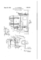
- Fig. 1 is an end elevational view of an engine equipped with the apparatus
- Fig. 2 is-a side elevational view of the en- Fig. 2a is a vertical sectional view on an enlarged scale through the fuel pump substantially on the line 2a-2a of Fig. 2;
- Fig. 3 is a top plan view on an enlarged scale of the safety device
- Fig. 4 is a, longitudinal sectional View substantially on the line 4-4 of Fig. 3, showing the position of the parts when the engine is running with a full head of pressure in the circulating systems;
- Fig. 5 is a view similar to Fig. 4 showing the parts when pressure is lacking in the circulating systems
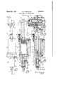
- Fig. 6 is a diagram showing a piping arrangement for using a starting fluid while the oil pressure or water pressure is building
- a prime mover A in the form of an internal combustion engine, specifically a two cylinder Diesel engine, is shown having fuel'pumps at B and a governor O of any suitable or desired ty 6 which controls the speed and operation of t e engine by means of a control lever 0 which acts through linkage upon a by-pass valve pressure type.
- the present invention utilizes the pressures obtaining in these systems to actuate "an auxiliary control which is additional to the governor C.
- the device provides an oil cylinder 14 in which is mounted for sliding movement a piston 15 to which rod 12 is connected, a dowel pin '16 being provided in the casing to prevent rod 12 from turning.
- Aj coil spring 17 partly housed in-a counterbore in piston 15 and engaging the end of the cylinder through which rod 12 projects, is provided for normally maintaining piston 15 at the extreme end of cylinder 14 (Fig. 5) and for yieldingly opposing the pressure of the lubricant admitted through pipe 10.
- a water cylinder 18 in the form of a head secured to cylinder 14 and in axial alignment with the latter provides a chamber of smaller capacity to which water from the cooling system has access through pipe 7.
- a piston 19 within the chamber backed by a coil spring 20 opposes the pressure of the entering water.
- Connecting the water chamber and the oil chamber is a reduced bore 21 in which is mounted for sliding movement a cylindrical valve 22 having a central groove 22a forming spaced heads.
- valve 22 may be an extension of piston 19, by preference'it is a separate piece loosely secured to the latter in any suitable manner as by a tongue and socket connection with a pin 23 to hold the parts against separation.
- Valve 22 controls both the inlet and the outlet of the oil chamber. When .thevalve is in the position shown in Fig.
- a clearance w (Figs.s3 and 4) is the predetermined minimum and may be utilized to give a signal or alarm so that the operator will be notified that his engine is about to stop and he 'will be given an opportunity to determine thecause of the improper operating condition and makeadjustments while the engine is still running, thus preventing the inconvenience of an undesired stop.
- any desired signalling apparatus may be provided, that shown is of the electrical type and comprises a contact screw 26 mounted on a hard rubber pin 27 adjacent the outer end of rod 12 and a cooperating contact in the form of a flat spring 28 secured to but insulated from a bracket 29 projecting from the casing of device D.
- a screw 30 on the outer end of bracket 29 provides for the adjustment of the contact spring 28 so that proper contact with screw 26 may be secured without unnecessarily increasing the sliding-resistance.
- Leads Z and Z extend to contacts 26 and 28 from a source of power such as a dynamo or battery m, and thecircuit includes the signalling apparatus 8 which may be the magnet .coil of a solenoid or of an electric bell, or the filament of an electric light.
- auxiliary hand 'pump 31 discharging into a manifold 32 into which the motor-driven oil pump 11 connects and from which extends the oil pipe 10 to device D, may be provided to build upthe lubricating oil pressure and hold it long enough to allow the motor-driven pump 11 to deliver and maintain the necessary pressure to release the governor lever arm '0. If the engine is not equipped with an auxiliary, lubricating oil pump or if the cooling water is not taken from a water pressure line but delivered from a pump'driven bv the motor itself.
- 33 .and 34 are one-way check valves and 35 is a pilot valve operated by the control shaft which is turned by the hand wheel 36 (Fig.1) thus permit ting the starting fluid from supply manifold 37 to enter the lines 7 or 10', or both, when the control handwheel 36 is in the starting position only.
- valve 35 will i be closed and the remaining starting fluid in cylinders 14 and 18 irill slowly leak out giving the engine time to start and build up the oil and water pressures.
- valve means operated by one of said pistons for controlling the admission of fluid to the ether chamber, and means actuated by the other of said pistons for reducing the speed of-the engine when the pressure in either of said systems fails.
- speed governor arranged to actuate a control lever, of a safety device providing a chamber receiving fluid from the cooling circuit and a second chamber receiving. fluid from the lubricating circuit, a piston in each of said chambers, a spring in each chamber acting against the piston therein yieldingly to oppose the pressure of the fluid admitted there- 'to, means including a valve actuated by the piston of said first or cooling chamber for controlling the inlet and outlet of said lubricating chamber, a rod extending from said lubricant piston arranged to actuate said governor control lever during movement in one direction only, cooperating signalling means on said rod and said device, and manual means for admitting a gaseous pressure fluid to said device to permit starting of the engine.
- a safety device for an internal combustion engine having a circuit through which a liquid is circulated under pressure comprising a casing providing a chamber connected to said circuit, a member within said chamber arranged for movement under the pressure of saidliquid, and resilient means engaging said 7 member for opposing movement of the latter by said liquid, said member having a part extending beyond said casing for operating governor or other controlmeans for the engine.
- a safety device for an internal combuss tion engine having a circuit through which a liquid is circulated under pressure comprising a casing providing a chamber connected to said circuit, a member within said chamber arranged for movement under the pressure of said liquid, and'resilient means engaging said member for opposing movement of the latter by said liquid, said member having a I part extending beyond said casing for operating governor or other cont-rolmeans for the engine, and signalling means arranged to operate on movement of said member in one direction.
- a safety device for internal combustion engines having a pressure cooling system and a pressure lubricating system comprising- 'ing a casing providing two chambers,' each chamberbeing connected into one of said 'systems, pistons in' said chamber arranged to be moved by the pressure fluid from sa1d-sys-,
- A. safety device for, lnternal combus t1on engines having a pressure cooling system and a pressure lubricating system comprising a easing providing two chambers
- each chamber being connected into one of said 7 systems, pistons in said chambers arranged to be moved by the pressure fluids from said sysl tems, springs opposing the movement of said pistons, means including a valve actuated by the piston in said cooling system chamber for controlling the inlet and outlet of said lubricant system chamber, a rod extending from the piston subject tolubrica nt pressure extending-beyond-said casing for operating governor or other control means-for the engine, and signallmg means lncludlng contacts, on
Landscapes
- Engineering & Computer Science (AREA)
- Mechanical Engineering (AREA)
- General Engineering & Computer Science (AREA)
- Chemical & Material Sciences (AREA)
- Combustion & Propulsion (AREA)
- Output Control And Ontrol Of Special Type Engine (AREA)
Description
March 1932- N. E. WERNBERG SAFETY DEVICE FOR PRIME MOVERS I Filed Aug. 28, 1928 2 Sheets-Sheet 1 A TTORNE Y.
March 29, 1932. I E, WERNBERG 1,851,611
SAFETY DEVICE FOR PRIME MOVERS Filed Aug. 28, 1928 2 Sheets-Sheet 2 r. INVENTOR.
A/feb" E We/wbe/g A TTORNE Y.
Patented Mar. 29, 1932 UNITED STATES PATENT-OFFICE NIELS E. WERNBERG, F FRANKLIN, PENNSYLVANIA, ASSIGNOR To CHICAGO PNEU- MATIC TOOL COMPANY, OF NEW YORK, N. Y., A CORPORATION 'OF NEW JERSEY SAFETY DEVICE FOR PRIME MOVERS Application filed August as, 1928. Serial No. 302,507.
This invention relates to the operation and control of prime movers with articular reference to those utilizing a me ium which is circulated under pressure. It has special adaptation to prime movers such as internal combustion engines which have a force feed lubricating system or a cooling system, or both, and have an energy supply which can be controlled mechanically either directly by means of a cut-off or a by-pass on the energy supply line, or indirectly through a governor.
One object of the invention is to stopthe engineautomatically upon failure of circulation of either medium or in the event of a dangerous reduction in the operating pressure of the circulated medium. Another object is to make such a safety device simple and compact and readily adaptable to existing types of engines as well as to newengines Another object is to arrange the safety device so as .notto interfere with known types of speed governors. Other objects will be apparent from the detailed description which follows:
The present invention provides forf'stopping an engine automatically whenever the pressure of the lubricant or cooling medium drops below a predetermined value, which may be fixed as a minimum to prevent damage to the engine from lack of lubrication or' cooling. The safety device may be arranged to I stop the engine by acting through the governor'linkage. The invention further contemplates giving a Warning signal before the engine is actually stopped so that the-engineer may have an opportunity to remedy the trouble and thus prevent complete cessation of operation.
In order'to illustrate the invention, one concrete embodiment thereof is shown in the accompanying drawings in which: Fig. 1 is an end elevational view of an engine equipped with the apparatus;
1 gine.shown in Fig. 1;
Fig. 2 is-a side elevational view of the en- Fig. 2a is a vertical sectional view on an enlarged scale through the fuel pump substantially on the line 2a-2a of Fig. 2;
Fig. 3 is a top plan view on an enlarged scale of the safety device;
Fig. 4 is a, longitudinal sectional View substantially on the line 4-4 of Fig. 3, showing the position of the parts when the engine is running with a full head of pressure in the circulating systems;
Fig. 5 is a view similar to Fig. 4 showing the parts when pressure is lacking in the circulating systems;
Fig. 6 is a diagram showing a piping arrangement for using a starting fluid while the oil pressure or water pressure is building In the embodiment of the invention'chosen for the purpose of illustration a prime mover A in the form of an internal combustion engine, specifically a two cylinder Diesel engine, is shown having fuel'pumps at B and a governor O of any suitable or desired ty 6 which controls the speed and operation of t e engine by means of a control lever 0 which acts through linkage upon a by-pass valve pressure type. In view of the overheating and damage to the engine, which will result if there is an insufficient supply of cooling Water in the cooling system or of lubricant in thelubricating system, the present invention utilizes the pressures obtaining in these systems to actuate "an auxiliary control which is additional to the governor C. I
.The safety device shown at D in Figs. 1
and 2 is supported by a bracket E projecting from the governor shaft housing 0. Water from the cooling system is supplied to device D through a pipe? and drainage therefrom is provided fonby a pipe 8 which discharges into a water funnel 9. Oil from the lubricating system is "supplied to device D by pipe 10 leading from the oil pump 11 (Fig. 2).
Drainage and leakage ofoil from device D passes back into the crank case through pipe 11a. Projecting from device D is a rod 12 having a stop projection 13 arranged to engage the governor control lever 0 upon movement in one direction. The arrangement is such that the governor lever arm works independently of device D in the position shown in Figs. 1, 3 and 4, which correspond to the or the cooling water pressure should dropbelow a predetermined minimum, the stop pin on rod 12 will pull the lever c to the stop position shown in Fig. 5 whereupon the bypass lifting shaft 5 of the fuel pump will be turned to a position in which the fuel supply will be by-passed instead of injected into the cylinders of engine A, thus causing the'engine to stop.
- The mechanism by which rod 12 is actuated on failure of the oil or cooling water supply will now be described, attention being directed'particularly to Figs. 3, 4 and 5 which show the safety device D on an enlarged scale. The device provides an oil cylinder 14 in which is mounted for sliding movement a piston 15 to which rod 12 is connected, a dowel pin '16 being provided in the casing to prevent rod 12 from turning. Aj coil spring 17 partly housed in-a counterbore in piston 15 and engaging the end of the cylinder through which rod 12 projects, is provided for normally maintaining piston 15 at the extreme end of cylinder 14 (Fig. 5) and for yieldingly opposing the pressure of the lubricant admitted through pipe 10.
A water cylinder 18 in the form of a head secured to cylinder 14 and in axial alignment with the latter provides a chamber of smaller capacity to which water from the cooling system has access through pipe 7. A piston 19 within the chamber backed by a coil spring 20 opposes the pressure of the entering water. Connecting the water chamber and the oil chamber is a reduced bore 21 in which is mounted for sliding movement a cylindrical valve 22 having a central groove 22a forming spaced heads. While valve 22 may be an extension of piston 19, by preference'it is a separate piece loosely secured to the latter in any suitable manner as by a tongue and socket connection with a pin 23 to hold the parts against separation. Valve 22 controls both the inlet and the outlet of the oil chamber. When .thevalve is in the position shown in Fig. 4, oil admitted through pipe 10 has accessthrough groove 22a in the valve to an angular bore 24 (Fig, 3) opening into the oil chamber. In this position the outlet passage 25 (Figs. 4 and 5) which communicates with drain pipe 11a by bore 25a in cylinder 14 is sealed by the inner head of valve 22. With a failing water pressure which permits expansion of spring 20, piston 19 and valve 22 take the position shown in Fig. 5 wherein the outer head of valve 22 now seals off the, inlet connection 10 but opens up outlet passage 25 sothat the oil pressure in cylinder 14 is relieved permitting spring 17 to force piston 15 to the position shown in Fig. 5.
If the water pressure is maintained but the the-water pressure in the position shown in Fig. 4 but the failing oil pressure will enable.
spring 17 to force the oil in cylinder 14 out through the inlet connection 24 across groove 22a in the .valve back .into the inlet pipe 10 withthe result that stop 13 on rod12 will engage governor lever cand drag it to the stop'posit-ion shown in broken lines in Fig. .4.
In the normal engine running position of the parts a clearance w (Figs.s3 and 4) is the predetermined minimum and may be utilized to give a signal or alarm so that the operator will be notified that his engine is about to stop and he 'will be given an opportunity to determine thecause of the improper operating condition and makeadjustments while the engine is still running, thus preventing the inconvenience of an undesired stop. While any desired signalling apparatus may be provided, that shown is of the electrical type and comprises a contact screw 26 mounted on a hard rubber pin 27 adjacent the outer end of rod 12 and a cooperating contact in the form of a flat spring 28 secured to but insulated from a bracket 29 projecting from the casing of device D. A screw 30 on the outer end of bracket 29 provides for the adjustment of the contact spring 28 so that proper contact with screw 26 may be secured without unnecessarily increasing the sliding-resistance. Leads Z and Z (Fig. 3) extend to contacts 26 and 28 from a source of power such as a dynamo or battery m, and thecircuit includes the signalling apparatus 8 which may be the magnet .coil of a solenoid or of an electric bell, or the filament of an electric light.
It will be obvious from the construction of device D that the engine cannot be started. before cooling water at the proper pressure is available or before proper lubricating oil pressure has been built up. An auxiliary hand 'pump 31, discharging into a manifold 32 into which the motor-driven oil pump 11 connects and from which extends the oil pipe 10 to device D, may be provided to build upthe lubricating oil pressure and hold it long enough to allow the motor-driven pump 11 to deliver and maintain the necessary pressure to release the governor lever arm '0. If the engine is not equipped with an auxiliary, lubricating oil pump or if the cooling water is not taken from a water pressure line but delivered from a pump'driven bv the motor itself. other means for releasing the governor lever arm 0 must be provided -to give the engine time to start and build up oil and water pressure have reached the proper value. This, however, requires assistance in starting the engine which maynot always be available. An automatic starting control arrangement is accordingly preferable and can be obtained by employing a starting fluid,
. such as compressed air. Fig. 6 is a diagramwill enter the oil cylinder 14 or the water c 1-= matic showing of an arrangement for this purpose. As shown, a connection is made with the cooling water line 7 t or with the lubricant supply line 10', or both, depending upon whether either or both of these systems is driven by the engine itself. 33 .and 34 are one-way check valves and 35 is a pilot valve operated by the control shaft which is turned by the hand wheel 36 (Fig.1) thus permit ting the starting fluid from supply manifold 37 to enter the lines 7 or 10', or both, when the control handwheel 36 is in the starting position only. Thereupon' the starting fluid inder 18, or both, and the pressure supply thereto will move rod 12 to the normal run n-ing position (Figs. 3 and 4). As soon as control handwhcel 36 is turned from starting position to running position valve 35 will i be closed and the remaining starting fluid in cylinders 14 and 18 irill slowly leak out giving the engine time to start and build up the oil and water pressures. To this end it is to be understood that the fits of pistons 15 and 19 must be liquid tight but not air chambers. valve means operated by one of said pistons for controlling the admission of fluid to the ether chamber, and means actuated by the other of said pistons for reducing the speed of-the engine when the pressure in either of said systems fails.
2. The combination with an engine having a .cooling system and a lubricating system, both systems operating under pressure.- of a safety device providing chambers receiving fluid from both said systems, pistons in said chambes, valve means operated by one of said pistons for controlling the admission of fluid to the other chamber, a rod movable with the other of said pistons, and means engaged by said rod on movement in one direction for reducing the speed of the engine if the pressure in either of said systems becomes reduced and to stop theengine when the pressure in the system reaches a predetermined low value.
3. The combination with an engine having a cooling system and a lubricating system, both systemshoperating under pressure, of a safety device providing chambers receiving fluid from both said systems, said chambers. each having an inlet and a drain, springpressed pistons in. said chambers opposing the fluids admitted thereto, the piston for one of said chambers having means for controlling .the inlet and the drain of the other chamber, and means controlled by the position of the piston in the last-named chamber for governing the operation of the engine.
. 4. The combination with an internal combustion engine having a cooling water cir cuit and a lubricating circuit and. having a.-
speed governor arranged to actuate a control lever, of a safety device providing a chamber receiving fluid from the cooling circuit and a second chamber receiving. fluid from the lubricating circuit, a piston in each of said chambers, a spring in each chamber acting against the piston therein yieldingly to oppose the pressure of the fluid admitted there- 'to, means including a valve actuated by the piston of said first or cooling chamber for controlling the inlet and outlet of said lubricating chamber, a rod extending from said lubricant piston arranged to actuate said governor control lever during movement in one direction only, cooperating signalling means on said rod and said device, and manual means for admitting a gaseous pressure fluid to said device to permit starting of the engine.
5. A safety device for an internal combustion engine having a circuit through which a liquid is circulated under pressure comprising a casing providing a chamber connected to said circuit, a member within said chamber arranged for movement under the pressure of saidliquid, and resilient means engaging said 7 member for opposing movement of the latter by said liquid, said member having a part extending beyond said casing for operating governor or other controlmeans for the engine.
I 6. A safety device for an internal combuss tion engine having a circuit through which a liquid is circulated under pressure comprising a casing providing a chamber connected to said circuit, a member within said chamber arranged for movement under the pressure of said liquid, and'resilient means engaging said member for opposing movement of the latter by said liquid, said member having a I part extending beyond said casing for operating governor or other cont-rolmeans for the engine, and signalling means arranged to operate on movement of said member in one direction.
7. A safety device for internal combustion engines having a pressure cooling system and a pressure lubricating system compris- 'ing a casing providing two chambers,' each chamberbeing connected into one of said 'systems, pistons in' said chamber arranged to be moved by the pressure fluid from sa1d-sys-,
tems, springs opposing the movement of said pistons, means including a valve actuated by one of said pistons for controlling the inlet andoutlet of the other of said chambers, and a rod extending from-the other of said pistons beyond said casing for operating governor or other control means for the engine.
8. A. safety device for, lnternal combus t1on engines having a pressure cooling system and a pressure lubricating system comprising a easing providing two chambers,
each chamber being connected into one of said 7 systems, pistons in said chambers arranged to be moved by the pressure fluids from said sysl tems, springs opposing the movement of said pistons, means including a valve actuated by the piston in said cooling system chamber for controlling the inlet and outlet of said lubricant system chamber, a rod extending from the piston subject tolubrica nt pressure extending-beyond-said casing for operating governor or other control means-for the engine, and signallmg means lncludlng contacts, on
said rod and said casing.-
ed by me at Franklin, inthe county Sign of (mango and State'of Pa., this 22d day.
of August, 1928.
' NIELS E. WERNBERG.
Priority Applications (1)
| Application Number | Priority Date | Filing Date | Title |
|---|---|---|---|
| US302507A US1851611A (en) | 1928-08-28 | 1928-08-28 | Safety device for prime movers |
Applications Claiming Priority (1)
| Application Number | Priority Date | Filing Date | Title |
|---|---|---|---|
| US302507A US1851611A (en) | 1928-08-28 | 1928-08-28 | Safety device for prime movers |
Publications (1)
| Publication Number | Publication Date |
|---|---|
| US1851611A true US1851611A (en) | 1932-03-29 |
Family
ID=23168023
Family Applications (1)
| Application Number | Title | Priority Date | Filing Date |
|---|---|---|---|
| US302507A Expired - Lifetime US1851611A (en) | 1928-08-28 | 1928-08-28 | Safety device for prime movers |
Country Status (1)
| Country | Link |
|---|---|
| US (1) | US1851611A (en) |
Cited By (4)
| Publication number | Priority date | Publication date | Assignee | Title |
|---|---|---|---|---|
| US2563834A (en) * | 1945-05-28 | 1951-08-14 | Woodward Governor Co | Safety control for prime movers |
| US3138144A (en) * | 1962-11-26 | 1964-06-23 | Roy J Armbrust | Protective apparatus for internal combustion engines |
| US3977384A (en) * | 1971-07-31 | 1976-08-31 | Motoren- Und Turbinen-Union Friedrichshafen Gmbh | Internal combustion engine oil pressure loss safety device |
| US4913103A (en) * | 1988-10-24 | 1990-04-03 | Outboard Marine Corporation | Marine propulsion device low liquid pressure warning system |
-
1928
- 1928-08-28 US US302507A patent/US1851611A/en not_active Expired - Lifetime
Cited By (4)
| Publication number | Priority date | Publication date | Assignee | Title |
|---|---|---|---|---|
| US2563834A (en) * | 1945-05-28 | 1951-08-14 | Woodward Governor Co | Safety control for prime movers |
| US3138144A (en) * | 1962-11-26 | 1964-06-23 | Roy J Armbrust | Protective apparatus for internal combustion engines |
| US3977384A (en) * | 1971-07-31 | 1976-08-31 | Motoren- Und Turbinen-Union Friedrichshafen Gmbh | Internal combustion engine oil pressure loss safety device |
| US4913103A (en) * | 1988-10-24 | 1990-04-03 | Outboard Marine Corporation | Marine propulsion device low liquid pressure warning system |
Similar Documents
| Publication | Publication Date | Title |
|---|---|---|
| US4157744A (en) | Lubricating and cooling engine system component | |
| US3827236A (en) | Cooling systems for turbocharger mechanisms | |
| US3788776A (en) | Compressor unloading control | |
| US2102514A (en) | Auxiliary oiling device | |
| US2545856A (en) | Temperature controlled fuel pump for gas turbines | |
| US2761387A (en) | Fuel system | |
| US3202143A (en) | Pressure and temperature responsive engine shut-down devices | |
| US3422807A (en) | Preliminary lubrication device | |
| US3045419A (en) | Lubrication systems and protective controls for turbocharged engines | |
| US1851611A (en) | Safety device for prime movers | |
| EP0058268B1 (en) | A spring actuated piston pump and a turbo-charged engine utilising such a pump | |
| US4231384A (en) | Apparatus for draining a cooling system | |
| US2640423A (en) | Fuel system | |
| US1904320A (en) | Pipeline booster system | |
| US4126108A (en) | Apparatus for draining a cooling system | |
| US3159166A (en) | Engine safety control | |
| US2960082A (en) | Engine starting and protective shutdown system | |
| US2388523A (en) | Lubricant heating system for turbosuperchargers and the like | |
| US2426639A (en) | Pressure regulator for pumps | |
| US1606060A (en) | Compressor-controlling apparatus | |
| US2109832A (en) | Lubricating device | |
| US1083568A (en) | Pumping plant. | |
| US1685868A (en) | Controller governor | |
| US1988164A (en) | Pump mechanism | |
| US3426962A (en) | Overtemperature and lubricant loss protector for compressors |