US185159A - Improvement in expanthng-mandrelb for turning piston-rings - Google Patents
Improvement in expanthng-mandrelb for turning piston-rings Download PDFInfo
- Publication number
- US185159A US185159A US185159DA US185159A US 185159 A US185159 A US 185159A US 185159D A US185159D A US 185159DA US 185159 A US185159 A US 185159A
- Authority
- US
- United States
- Prior art keywords
- ring
- rings
- fingers
- mandrelb
- expanthng
- Prior art date
- Legal status (The legal status is an assumption and is not a legal conclusion. Google has not performed a legal analysis and makes no representation as to the accuracy of the status listed.)
- Expired - Lifetime
Links
- XEEYBQQBJWHFJM-UHFFFAOYSA-N Iron Chemical compound [Fe] XEEYBQQBJWHFJM-UHFFFAOYSA-N 0.000 description 2
- 210000003127 knee Anatomy 0.000 description 2
- 229910001018 Cast iron Inorganic materials 0.000 description 1
- 229910052742 iron Inorganic materials 0.000 description 1
- 239000002184 metal Substances 0.000 description 1
- 229910052751 metal Inorganic materials 0.000 description 1
- 238000000034 method Methods 0.000 description 1
Images
Classifications
-
- B—PERFORMING OPERATIONS; TRANSPORTING
- B23—MACHINE TOOLS; METAL-WORKING NOT OTHERWISE PROVIDED FOR
- B23B—TURNING; BORING
- B23B31/00—Chucks; Expansion mandrels; Adaptations thereof for remote control
- B23B31/40—Expansion mandrels
- B23B31/404—Gripping the work or tool by jaws moving radially controlled by conical surfaces
-
- Y—GENERAL TAGGING OF NEW TECHNOLOGICAL DEVELOPMENTS; GENERAL TAGGING OF CROSS-SECTIONAL TECHNOLOGIES SPANNING OVER SEVERAL SECTIONS OF THE IPC; TECHNICAL SUBJECTS COVERED BY FORMER USPC CROSS-REFERENCE ART COLLECTIONS [XRACs] AND DIGESTS
- Y10—TECHNICAL SUBJECTS COVERED BY FORMER USPC
- Y10T—TECHNICAL SUBJECTS COVERED BY FORMER US CLASSIFICATION
- Y10T29/00—Metal working
- Y10T29/49—Method of mechanical manufacture
- Y10T29/49229—Prime mover or fluid pump making
- Y10T29/49274—Piston ring or piston packing making
- Y10T29/49279—Piston ring or piston packing making including rolling or die forming, e.g., drawing, punching
-
- Y—GENERAL TAGGING OF NEW TECHNOLOGICAL DEVELOPMENTS; GENERAL TAGGING OF CROSS-SECTIONAL TECHNOLOGIES SPANNING OVER SEVERAL SECTIONS OF THE IPC; TECHNICAL SUBJECTS COVERED BY FORMER USPC CROSS-REFERENCE ART COLLECTIONS [XRACs] AND DIGESTS
- Y10—TECHNICAL SUBJECTS COVERED BY FORMER USPC
- Y10T—TECHNICAL SUBJECTS COVERED BY FORMER US CLASSIFICATION
- Y10T82/00—Turning
- Y10T82/25—Lathe
- Y10T82/2531—Carriage feed
- Y10T82/2541—Slide rest
- Y10T82/2543—Multiple tool support
-
- Y—GENERAL TAGGING OF NEW TECHNOLOGICAL DEVELOPMENTS; GENERAL TAGGING OF CROSS-SECTIONAL TECHNOLOGIES SPANNING OVER SEVERAL SECTIONS OF THE IPC; TECHNICAL SUBJECTS COVERED BY FORMER USPC CROSS-REFERENCE ART COLLECTIONS [XRACs] AND DIGESTS
- Y10—TECHNICAL SUBJECTS COVERED BY FORMER USPC
- Y10T—TECHNICAL SUBJECTS COVERED BY FORMER US CLASSIFICATION
- Y10T82/00—Turning
- Y10T82/26—Work driver
- Y10T82/266—Mandrel
- Y10T82/268—Expansible
Definitions
- the object of our invention is to more rapidly and truly center and finish metal piston-pack- 4 ing rings by one setting and tool operation
- a tool-holder and rest On each side of the chuck is a tool-holder and rest, in one of which, on the front side, are placed two cutters, t t, for cutting the sides of the ring, and also a shoulder-tool for truing the ring preparatory to ,the action of the cutting-tools, while the tool D, on the opposite face of the ring, is to cut across its face, to thereby enable us to produce a piston-ring, mathematically centered and finished, sides and face, at one operation or chucking.
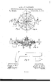
- Figures 1 and 2 are elevation views; Fig. 3, a section through the center of the mandrel and chuck from D to t. Fig. 4 is a full-sized side and edge view of one of the radial fingers.
- a a, Fig. 3 is a cone-guide stud.
- b Z) b b are bolts for nuts to hold the face or front plate in position for work.
- 0 G is the expandingcone. 0 0 represent cut-away portions of the knees of fingers 0, (shown at K, Fig. 4,) to allow of greater radial play to said fingers.
- c c" is a collar around the base of the conepast the heel of the cone.
- stud a to prevent the fingers from getting 61 d d are set-screws and nuts for holding the tools.
- 9 g are friction-springs, one behind each finger O to keep it in position when the pressure of the cone is withdrawn.
- K, Fig. 4 is the knee, on finger O, to supply greater steadying support to the fingers against the cone 0.
- L L is the main or back plate, in which are the radial grooves for the reception of the fingers O O, and in which the springs g g are recessed to operate, as already described.
- a n is a nut on the axial stud a for pressing the cone.
- O O are the radial fingers to be simultaneously expanded by the cone 0 acted on by the nut n on the stud a a.
- P is the face or front plate of the chuck, and it is bolted over the fingers to the back plate L L by the bolts 1) b b, 8110.
- 1- 1' is the packing-ring in place, and trued for the proper action of the turning-tools t t and the cross-facer D.
- S S are the ends of the tool-holders, either of which can be and is intended to be used as a shoulder to true the ring against. 8' s are studs in the back plate to secure it to the lathe.
- t t is the parallel-sided tool-holder, provided with seats for the cutting-tools t t.
- c c c, Fig. 4 represent the chamfered and nicked ends of the fingers, to render it nearly certain that no sand-lump, or other prominence on the cast ring, can prevent true centering.
- the ring cast in a truly circular cast-iron pattern is to be placed over the fingers while they are sufficiently withdrawn.
- cone 0 J is pressed down, and extends the fingers to the inner faceof the ring, oentering and securing it, and leaving it ready for work, and when the tool-shoulder s is brought up and the ring trued against it by turning the lathe,the tool-rest t t is then set up so as to divide the out on the ring.
- the lathe movement then feeds the cutters or tools t t until the entire depth of the ring is out perfectly parallel.
- the cross-feed tool D has dressed the outer face of the ring, provided one cut sufficed to bring it to gage, sides and face; otherwise a second cut must By turning the axial nut n the 2 v l85,l59
Landscapes
- Engineering & Computer Science (AREA)
- Mechanical Engineering (AREA)
- Turning (AREA)
Description
La R.,& W. BARTLETT.
EXPANDING MANDRELS FOR TURNING PISTON RINGS.
Patented Dec.12, 1876.
T J59. I i J61 11 17/1/55555, M/I/[A/TO/E; XWW 0. flaw 5% Ma w 6m THEIGRAPHIC C(LNX Unrrnn @LAiEg .LA ROY BARTLETT AND WINTHROP BARTLETT, OF sT. LOUIS, MISSOURI.
iMPR'OV EMENT IN EXPAN'D'lN'G-MANDREL'S FOR TURNING Pi'STON-RINGS.
Specification forming part of Letters Patent No. l5,l59, dated December 12, 1876; application filed July 18, 1876.
'Rings, which improvement is fully set forth in the following specification, reference being had to the accompanying drawings with their uniformly corresponding letters of reference.
The object of our invention is to more rapidly and truly center and finish metal piston-pack- 4 ing rings by one setting and tool operation,
which we accomplish by the combination, with achuck,of an expanding-mandrel,which, by the admission of varying-sized cones for expanding certain radiating fingers, can thereby be used to secure nearly every sized ring it is desired to finish. On each side of the chuck is a tool-holder and rest, in one of which, on the front side, are placed two cutters, t t, for cutting the sides of the ring, and also a shoulder-tool for truing the ring preparatory to ,the action of the cutting-tools, while the tool D, on the opposite face of the ring, is to cut across its face, to thereby enable us to produce a piston-ring, mathematically centered and finished, sides and face, at one operation or chucking.
For a further understanding of our invention we proceed to describe and detail its parts.
Figures 1 and 2 are elevation views; Fig. 3, a section through the center of the mandrel and chuck from D to t. Fig. 4 is a full-sized side and edge view of one of the radial fingers.
By way of detailed illustration, A, Figs. 1
and 2, is an arrow, showing the proper direction of lathe motion. B is an arrow, showing the direction of movement of the parallel double-sided cutter-holder and cutters. D is a cutter for finishing the face of the ring. E is an arrow showing the direction of movement of the reversed cutter for cross-facing. a a, Fig. 3, is a cone-guide stud. b Z) b b are bolts for nuts to hold the face or front plate in position for work. 0 G is the expandingcone. 0 0 represent cut-away portions of the knees of fingers 0, (shown at K, Fig. 4,) to allow of greater radial play to said fingers. c c" is a collar around the base of the conepast the heel of the cone.
stud a, to prevent the fingers from getting 61 d d are set-screws and nuts for holding the tools. 9 g are friction-springs, one behind each finger O to keep it in position when the pressure of the cone is withdrawn. K, Fig. 4, is the knee, on finger O, to supply greater steadying support to the fingers against the cone 0. L L is the main or back plate, in which are the radial grooves for the reception of the fingers O O, and in which the springs g g are recessed to operate, as already described. a n is a nut on the axial stud a for pressing the cone. 0 O O are the radial fingers to be simultaneously expanded by the cone 0 acted on by the nut n on the stud a a. P is the face or front plate of the chuck, and it is bolted over the fingers to the back plate L L by the bolts 1) b b, 8110. 1- 1' is the packing-ring in place, and trued for the proper action of the turning-tools t t and the cross-facer D. S S are the ends of the tool-holders, either of which can be and is intended to be used as a shoulder to true the ring against. 8' s are studs in the back plate to secure it to the lathe. t t is the parallel-sided tool-holder, provided with seats for the cutting-tools t t. c c c, Fig. 4, represent the chamfered and nicked ends of the fingers, to render it nearly certain that no sand-lump, or other prominence on the cast ring, can prevent true centering. We prefer the edge when nearly sharpened to a point. We use ten or more of these radial fingers to better sustain and equalize the radial strain on the ring.
To operate our invention the ring cast in a truly circular cast-iron pattern is to be placed over the fingers while they are sufficiently withdrawn. cone 0 (J is pressed down, and extends the fingers to the inner faceof the ring, oentering and securing it, and leaving it ready for work, and when the tool-shoulder s is brought up and the ring trued against it by turning the lathe,the tool-rest t t is then set up so as to divide the out on the ring. The lathe movement then feeds the cutters or tools t t until the entire depth of the ring is out perfectly parallel. In the meanwhile the cross-feed tool D has dressed the outer face of the ring, provided one cut sufficed to bring it to gage, sides and face; otherwise a second cut must By turning the axial nut n the 2 v l85,l59
be taken. Both tools may act simultaneously or consecutively. the axial nut n is unscrewed, and by a tap on the face of the ring the fingers slip on their springs and liberate the ring. In this manner We are enabled to perfectly finish from twenty to twenty-five rings in one day, being four times as much work as by the ordinary method.
\Ve do not claim plain radial fingers to be set out or expanded by cones, for centering and holding in place piston-rings, nor radial fingers with reduced faces ends.
We claim as our invention- The two-plate chuck on an expanding-mandrel, the rear or fore chuck-plate, having radial.
When the ring is finished on their holding v .iron piston-rings in one operation.
LA ROY BARTLETT. WINTHROP BARTLETT.
Witnesses:
JOSEPH E. WARE, CHAS. E. WARE.
Publications (1)
| Publication Number | Publication Date |
|---|---|
| US185159A true US185159A (en) | 1876-12-12 |
Family
ID=2254564
Family Applications (1)
| Application Number | Title | Priority Date | Filing Date |
|---|---|---|---|
| US185159D Expired - Lifetime US185159A (en) | Improvement in expanthng-mandrelb for turning piston-rings |
Country Status (1)
| Country | Link |
|---|---|
| US (1) | US185159A (en) |
Cited By (3)
| Publication number | Priority date | Publication date | Assignee | Title |
|---|---|---|---|---|
| US2566304A (en) * | 1943-10-15 | 1951-09-04 | Burd Piston Ring Company | Method of and machine for making piston rings |
| US2724188A (en) * | 1952-06-30 | 1955-11-22 | William J Boiven | Expansible gauge |
| US3442164A (en) * | 1966-10-19 | 1969-05-06 | Bear Mfg Co | Brake disc lathe |
-
0
- US US185159D patent/US185159A/en not_active Expired - Lifetime
Cited By (3)
| Publication number | Priority date | Publication date | Assignee | Title |
|---|---|---|---|---|
| US2566304A (en) * | 1943-10-15 | 1951-09-04 | Burd Piston Ring Company | Method of and machine for making piston rings |
| US2724188A (en) * | 1952-06-30 | 1955-11-22 | William J Boiven | Expansible gauge |
| US3442164A (en) * | 1966-10-19 | 1969-05-06 | Bear Mfg Co | Brake disc lathe |
Similar Documents
| Publication | Publication Date | Title |
|---|---|---|
| JP6469715B2 (en) | Grinding machine and method for grinding a workpiece having an axial hole and a flat outer surface machined on both sides | |
| US20040218987A1 (en) | Cutting tool for rough and finish milling | |
| US2751663A (en) | Facing head, particularly for the milling of steel, bronze and cast iron | |
| US3405049A (en) | Cylindrical bore sizing and finishing device | |
| US3435502A (en) | Piston ring and method of manufacture thereof | |
| US185159A (en) | Improvement in expanthng-mandrelb for turning piston-rings | |
| US10005135B2 (en) | Rotary boring tool with detachable cutting inserts and method for machining a cylinder bore of a combustion engine | |
| CN110153870A (en) | A kind of TiC base steel bonded carbide end cap inner bore honing device and its Honing process method | |
| US7802945B2 (en) | Cutting tool for rough and finish milling | |
| US3027693A (en) | Work holder | |
| US2519476A (en) | Boring apparatus | |
| US402394A (en) | Boring-tool | |
| US3475802A (en) | Double-ended cutting insert and shank therefor | |
| US1230974A (en) | Jig. | |
| EP1700670A2 (en) | Super-abrasive machining tool and method of use | |
| US370484A (en) | Counterbore | |
| US431855A (en) | Lathe-carriage | |
| Kundrák et al. | Joint machining: hard turning and grinding | |
| US2237088A (en) | Method of forming pipe cutter wheels | |
| EP0154965B1 (en) | Internal grinding machine | |
| US1737990A (en) | Cutting tool | |
| US3025729A (en) | Tool holder | |
| US234966A (en) | con roy | |
| US355147A (en) | demead | |
| Коробко et al. | Modified Hexanit cutters for knurling of cylindrical shaft sections= Модифіковані фрези Hexanit для обрізання циліндричних секцій валів |