US185158A - Improvement in oil-can faucets - Google Patents
Improvement in oil-can faucets Download PDFInfo
- Publication number
- US185158A US185158A US185158DA US185158A US 185158 A US185158 A US 185158A US 185158D A US185158D A US 185158DA US 185158 A US185158 A US 185158A
- Authority
- US
- United States
- Prior art keywords
- cork
- opening
- faucets
- oil
- faucet
- Prior art date
- Legal status (The legal status is an assumption and is not a legal conclusion. Google has not performed a legal analysis and makes no representation as to the accuracy of the status listed.)
- Expired - Lifetime
Links
- 239000007799 cork Substances 0.000 description 11
- 239000007788 liquid Substances 0.000 description 2
- 239000002184 metal Substances 0.000 description 2
- 230000007547 defect Effects 0.000 description 1
- 238000004519 manufacturing process Methods 0.000 description 1
- 230000000284 resting effect Effects 0.000 description 1
Images
Classifications
-
- B—PERFORMING OPERATIONS; TRANSPORTING
- B65—CONVEYING; PACKING; STORING; HANDLING THIN OR FILAMENTARY MATERIAL
- B65D—CONTAINERS FOR STORAGE OR TRANSPORT OF ARTICLES OR MATERIALS, e.g. BAGS, BARRELS, BOTTLES, BOXES, CANS, CARTONS, CRATES, DRUMS, JARS, TANKS, HOPPERS, FORWARDING CONTAINERS; ACCESSORIES, CLOSURES, OR FITTINGS THEREFOR; PACKAGING ELEMENTS; PACKAGES
- B65D47/00—Closures with filling and discharging, or with discharging, devices
- B65D47/04—Closures with discharging devices other than pumps
- B65D47/06—Closures with discharging devices other than pumps with pouring spouts or tubes; with discharge nozzles or passages
- B65D47/12—Closures with discharging devices other than pumps with pouring spouts or tubes; with discharge nozzles or passages having removable closures
- B65D47/14—Closures with discharging devices other than pumps with pouring spouts or tubes; with discharge nozzles or passages having removable closures and closure-retaining means
- B65D47/147—Closures with discharging devices other than pumps with pouring spouts or tubes; with discharge nozzles or passages having removable closures and closure-retaining means for snap-on caps
- B65D47/148—Closures with discharging devices other than pumps with pouring spouts or tubes; with discharge nozzles or passages having removable closures and closure-retaining means for snap-on caps with internal parts
Definitions
- My invention relates to faucets for transportation-cans; and consists in certain improvements upon the faucet shown in my Patent No. 138,986, dated May 25, 1873, as hereinafter more fully set forth.
- a faucet consisting, essentially, of a screw-threaded ianged tube, partially closed at both ends by centrally-perforated disk, and a plunger working in said tube carrying a cork, which is made to press against the lower disk, and close the opening therein when the plunger is turned down.
- a difficulty is found to exist in this faucet.- EX- perience has demonstrated the fact that the cork placed in the lower end of the plunger is liable to be pressed into the opening in the lowerdiaphragm so firmly that when the plunger is unscrewed it frequently leaves the cork in the opening, thus preventing the liquid in the can from flowing out through said opening in the lower disk.
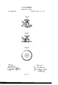
- Figure l of the drawings is a perspective view of the improved faucet.
- Fig. 2 is a vertical section thereof.
- Fig. 3 is a horizontal section taken below the plunger or valve, show ing the disk and the cork resting thereon.
- a is the body of the faucet, provided with a spout, I), and at the top with a screw-threaded tube, c, in which the spindle d, carrying the valve e, works.
- rlhese parts may be of cast or sheet metal. sheet metal, and has an annular groove, g, into which the body a is fitted and soldered.
- a hole, h is cut in the center of the disk for the valve opening.
- the cork i surrounding the opening hf, is annular in form, and rests on the disk f, being pressed somewhat into the groove g therein.
- the opening through the center of the cork is somewhat smaller than the opening in the diaphragm.
- the valve e presses against the cork and tightly closes the opening.
- the cork remains in place, and leaves the opening free for the liquid to flow out.
- the faucet is fastened or soldered to the can by means of the diskf, which is slightly bent or iianged at its outer ri in in aid of tlns purpose.
- a faucet for metallic cans consisting of a spouted tube or body attached to a larger perforated disk, which forms at once the valve-seat and attaching-plate for attaching the faucet to the can, avalve within the body or tube, and a cork of annular form, constituting a cushion for the valve-seat, substantially as described.
- the disk f is preferably of
Landscapes
- Engineering & Computer Science (AREA)
- Mechanical Engineering (AREA)
- Valve Housings (AREA)
Description
G. W. BANKER.
OIL-CAN FAUCET.
No; 185,158. Patented Dec. 12, 1876L 1 y wf raras 'IMPROVEMENT IN OIL-CAN FAUCETS.
Specification forming part of Letters Patent No. 185, [58, dated December 12, 1876; application led November 23, 187 6.
To all whom Ait may concern:
Be it known that I, GEORGE W. BANKER,
Aof New York, in the county of New York,
and in the State of New York, have invented a new and useful Improvement in Oil- Gan Faucets; and I do hereby declare that the following is a full, clear, and exact description thereof, reference being had to the accompa nying drawings, forming a part hereof.
My invention relates to faucets for transportation-cans; and consists in certain improvements upon the faucet shown in my Patent No. 138,986, dated May 25, 1873, as hereinafter more fully set forth.
In said patent is shown a faucet consisting, essentially, of a screw-threaded ianged tube, partially closed at both ends by centrally-perforated disk, and a plunger working in said tube carrying a cork, which is made to press against the lower disk, and close the opening therein when the plunger is turned down. A difficulty is found to exist in this faucet.- EX- perience has demonstrated the fact that the cork placed in the lower end of the plunger is liable to be pressed into the opening in the lowerdiaphragm so firmly that when the plunger is unscrewed it frequently leaves the cork in the opening, thus preventing the liquid in the can from flowing out through said opening in the lower disk. To overcome this defect I detach the cork from the plunger, and place a cork with a hole through its center in the chamber, between the lower end of the plunger and lower disk.
Figure l of the drawings is a perspective view of the improved faucet. Fig. 2 is a vertical section thereof. Fig. 3 is a horizontal section taken below the plunger or valve, show ing the disk and the cork resting thereon.
a is the body of the faucet, provided with a spout, I), and at the top with a screw-threaded tube, c, in which the spindle d, carrying the valve e, works. rlhese parts may be of cast or sheet metal. sheet metal, and has an annular groove, g, into which the body a is fitted and soldered. A hole, h, is cut in the center of the disk for the valve opening. The cork i, surrounding the opening hf, is annular in form, and rests on the disk f, being pressed somewhat into the groove g therein. The opening through the center of the cork is somewhat smaller than the opening in the diaphragm.
As the top 7c is screwed down, the valve e presses against the cork and tightly closes the opening. As the valve is screwed up, the cork remains in place, and leaves the opening free for the liquid to flow out. The faucet is fastened or soldered to the can by means of the diskf, which is slightly bent or iianged at its outer ri in in aid of tlns purpose.
What is claimed as the invention is- As an article of manufacture, a faucet for metallic cans, consisting of a spouted tube or body attached to a larger perforated disk, which forms at once the valve-seat and attaching-plate for attaching the faucet to the can, avalve within the body or tube, and a cork of annular form, constituting a cushion for the valve-seat, substantially as described.
GEO. W. BANKER.
Witnesses:
GEO. W. PEGK, WM. E. BRAID.
The disk f is preferably of
Publications (1)
| Publication Number | Publication Date |
|---|---|
| US185158A true US185158A (en) | 1876-12-12 |
Family
ID=2254563
Family Applications (1)
| Application Number | Title | Priority Date | Filing Date |
|---|---|---|---|
| US185158D Expired - Lifetime US185158A (en) | Improvement in oil-can faucets |
Country Status (1)
| Country | Link |
|---|---|
| US (1) | US185158A (en) |
-
0
- US US185158D patent/US185158A/en not_active Expired - Lifetime
Similar Documents
| Publication | Publication Date | Title |
|---|---|---|
| US9862591B2 (en) | Faucet with shearing valve element | |
| US185158A (en) | Improvement in oil-can faucets | |
| US599389A (en) | Oil-can | |
| US1116689A (en) | Filtering-faucet. | |
| US313249A (en) | Faucet | |
| US877063A (en) | Automatic ball-cock. | |
| US201513A (en) | Improvement in spouts for oil-cans | |
| US60223A (en) | Oscae f | |
| US103773A (en) | Improvement in valve-cocks for hydrants | |
| US729360A (en) | Waste and overflow fixture. | |
| US116245A (en) | Improvement in taps for liquid packages | |
| US243118A (en) | gassed | |
| US189760A (en) | Improvement in beer-faucets | |
| US1015614A (en) | Faucet. | |
| US102773A (en) | Improvement in faucets | |
| US296311A (en) | Device for tapping beer | |
| US201870A (en) | Improvement in safety-taps for casks | |
| US600766A (en) | Faucet | |
| US207492A (en) | Improvement in stench-traps | |
| US998282A (en) | Faucet. | |
| US213163A (en) | Improvement in sink-traps | |
| US971337A (en) | Glue-faucet. | |
| US2966925A (en) | Check valves | |
| US39795A (en) | Improvement in faucets | |
| US305128A (en) | andeeson |