US1851584A - Food handling apparatus - Google Patents
Food handling apparatus Download PDFInfo
- Publication number
- US1851584A US1851584A US445321A US44532130A US1851584A US 1851584 A US1851584 A US 1851584A US 445321 A US445321 A US 445321A US 44532130 A US44532130 A US 44532130A US 1851584 A US1851584 A US 1851584A
- Authority
- US
- United States
- Prior art keywords
- shaft
- freezer
- motor
- drive unit
- container
- Prior art date
- Legal status (The legal status is an assumption and is not a legal conclusion. Google has not performed a legal analysis and makes no representation as to the accuracy of the status listed.)
- Expired - Lifetime
Links
- 235000013305 food Nutrition 0.000 title description 12
- 238000010276 construction Methods 0.000 description 11
- 235000015243 ice cream Nutrition 0.000 description 4
- 238000006243 chemical reaction Methods 0.000 description 3
- 230000037431 insertion Effects 0.000 description 2
- 238000003780 insertion Methods 0.000 description 2
- 101150000595 CLMP gene Proteins 0.000 description 1
- 101100382322 Drosophila melanogaster Acam gene Proteins 0.000 description 1
- 241000577395 Thenus Species 0.000 description 1
- 239000006071 cream Substances 0.000 description 1
Images

Classifications
-
- A—HUMAN NECESSITIES
- A23—FOODS OR FOODSTUFFS; TREATMENT THEREOF, NOT COVERED BY OTHER CLASSES
- A23G—COCOA; COCOA PRODUCTS, e.g. CHOCOLATE; SUBSTITUTES FOR COCOA OR COCOA PRODUCTS; CONFECTIONERY; CHEWING GUM; ICE-CREAM; PREPARATION THEREOF
- A23G9/00—Frozen sweets, e.g. ice confectionery, ice-cream; Mixtures therefor
- A23G9/04—Production of frozen sweets, e.g. ice-cream
- A23G9/08—Batch production
- A23G9/10—Batch production using containers which are rotated or otherwise moved in a cooling medium
- A23G9/103—Batch production using containers which are rotated or otherwise moved in a cooling medium the container rotating about its own axis
Definitions
- This invention relates to food handling'apparatus, and particularly to ice cream freezers and driving means therefor,
- One of the principal objects of the invention is to provide'a foodhandling apparatus, such as anice cream freezer, of simple construction, having a readily detachable motor drive which is easily and quickly inserted in place and supported in effective drivingrelation with movable freezer parts.
- Another object of the invention is to provide a compact self-contained motor drive unit which is light in weight, is simple in construction, which may be interchangeably used on different kinds of'food handling apr paratus, which may be quicklyand easily inserted in place and detached, and which is provided with simple and effective-means for supporting and holding the drive unit in proper operating position.
- FIG. 1 is a side elevational view of an ice cream freezer embodying the present invention, parts being broken away and insection on the plane of the line 11 of'Fig. 2 to'illustrate the construction thereof; 7
- Fig. 2 is a plan view of the device of Fig. 1,;
- Fig. 3 is a partial end elevational view of the device of Fig. 1, a portion of the cover of the motor drive unit being broken away to illustrate the construction thereof; and a Fig. 4 is a perspective view of a detail.
- the yoke frame 17 extends: across and is supported ilpon the top of bucket-1d At one side, the bucketlO-is provided with upwardly extended spaced lugs 18 bolted at 19 to the sidewall of the bucket.- Adjacent the upper ends of, the lugs18 are shortinwardly extending circularpins 20 which are mounted in alignment and spaced sutficiently to permit the passage of shaft 15 'therebetween:
- the yoke frame 117 carries at [this end 'an outwardly extending flange 21 which is substantially rectangular in cross-section, this flange'being adapted to'be inserted when the yoke frame is held'inan upwardlyinclined position between the lugs18,,the.Q'p- I posite side edges of the flange underlying the pins 20; With the flange'21 thus inserted in position, the yoke frame is thenlowered about this mounting as a pivot, caregbeing-taken to properly center the upper protrudingtend 28 of
- the freezer shaft24e ex ⁇ tends within the food can"; 11, and (carries as'are customarily "provided in freezersof therein suitableiblades, paddles or scrapers l this character.”
- Thel'can '11 is rotatably mounted in a suitable centering lowerxbearj With the endT23 of shaft 24t properly ceni 1 ing, and is adapted toberotat'ed by theinterteredwithin socket 25, the yoke :fr'ame117 may then be further: lowered about the piv otal mounting 181 until the oppositeuendflr -35 co'rdance with this invention areadilyidetachable power actuated 'drlving means 1s of the frame 17 contacts with the top of vbucket at an area diametrically opposite I lugs 18.
- the yoke frame 17 is provided at this end with an outwardly projectinglip 29, and a latch pivoted at 31 to the side wall of bucket 10 is adapted to swinginto a position overlying-this lip 29, the latch hav wing acam surface 32 which engagesthe lip f andcams it downwardly into fixed position.
- the flange 21 slides further in under the pins 20, until the final camming action vof the latch 30 forces a curved surface 33 on the upper side of flange 21 into engage ment with the pins 20,,so that the flange 21 -is wedged in between the top of bucket 10 and the pins 20.
- the yoke frame isthus provided for rotating the shaft 15 comprising a motor drive unit supported by the ex- ,ten'ded end portion 34 of the shaft 15.
- connecting memberor spline 35 having 'a polygonal cross-section,' such as the herrago nal shape shownmore particularly in Fig. 4,
- This sleeve 37 ismounted for rotational movement within the housing 38 whichmay' be anintegrally extending part of the casing of- -the electric motor 39.
- the armature 40 "of the motor has'a shaft 41 which is rotat- 'ably mounted within the frame 38 in suit-' ablebearings 42;
- the shaft 41- carries at its outerend'a worm 44 which meshes with a worm gear 45 which is suitably fixed to a rotatable cross shaft 46.
- One end of shaft 46 supported in a bearing 47 provided in rthe housing 38, and theother end is supported in a bearing 48 carried by a cover --plate 49 removably attached to'the housing 38- by the; screws 5 0;
- a spur gear 51 which mesheswith a:
- the sleevey37- provides a hub- ,for gear 52 which may b e 'formed integrally therewith or'm'ay be attached thereto in any suitable manner.
- the combined sleeve 37 and gear 52 is rotatably -supported in bearings 53'and 54 formed in the housing 38gaiid cover 49 respectively]
- the driving connecim arts tend to tight-eni thetspline 35 on the tion betweenthe splinef35 and the shaftend 34 is in such a direction that rotationof the Ia suitable source of electrical energy, such as threaded end 34.
- the motor unit and sleeve 1 36 upon insertion on the spline slide inwardly until this movement is limited, such as by contact of the motor casing'with theside' wall 10; v
- the construction describedr also permits inserting the spline35 inplace on this screwthreaded end and then sliding the motor drive unit in place over the spline, the conversion "is accomplished, and the freezer ready for operation as a power j driven freezerl It is obvious that the splii e' 35 may be suitably modified as to the formior diame ter of the internal bore 36 to adapt it to the various shaft endsencountered.
- the pins 59 will then clear the top edge 60 by a greater amount; the operation of the motor unit will then set up a torque which will rotate the unit slightly about thesleeve 37 until one of the pins 59 contacts with the edge 60 to limit this rotative movement, the motor then operating in this slightly inclined position, as is clearly illustrated in Fig. 3.
- the motor unit is thus made practically universally applicable to food handling apparatus having a containerorframe, with a drive shaft mounted somewhat above the frame and extending outwardly beyond the end of the container or frame, so that the drive unit may be slipped on the end of the shaft and supported in operating position thereon, the motor casing being held against rotation thereon by inter-engaging surfaces between'the casing and frame or container.
- the motor unit may be made motor and the reduction gearing.
- the reduction gearing is designed to give a substantial speed reduction, so that conventional avallable motors can be used to obtain a proper rotative speed of the freezer shaft 15.
- suitable means may be provided ifdesired for positively retaining the unit in operating position; 'One suitable form for accomplishing this comprises pro-- iections or cylindrical enlargements 65 on the ends of pins 59, so that the projection'on the pins 59 which bears on the upper surface 60 of the freezer bucket during operation will engage the interior wall of the freezer bucket upon movement of the freezer unit away from the bucket to thereby positively restrain further movement of this character. In such case, sufficient clearance aboveqthe top of the freezer buclretis provided. for the pins 59,.
- a member adapted to be driven; within said container, a shaft in driving in LFood handlingapparatus of the charachandling, apparatus of the characterconnection with said member, a'circular' end portion on said shaft, a splined member rigidly mounted on said shaft end and havmg a polygonal driving surface, a motor drive unit having a driving sleeve with a;
- a freezer of the character described comprising an outer container, an inner container, a cross shaft, a driving interconnection between the inner container and the cross shaft to rotate the inner container, aprotruding end on said cross shaft, a splined member mounted. on the protruding end-of said cross shaft, a motor drive unit having a driving 4.
- a motor drive unit comprlslng a, motor, a casing therefor, a sleeve mounted 1n sa1d caslng andadapted to re-" ceive said driven-shaft in'driving engagemerit, a driving'mterconnection between sa1d motor and said sleeve including a reduction 1 gearing, said motor drive unit being adapted to besupported from said driven shaft, and means carriedby saidmotor drive unit adapted to engage acooperating part of said con-- tainer to preventrotation of the motor drive a unit about the shaft during the driving of i said shaft by themotor drive unit.
Landscapes
- Engineering & Computer Science (AREA)
- Manufacturing & Machinery (AREA)
- Life Sciences & Earth Sciences (AREA)
- Chemical & Material Sciences (AREA)
- Food Science & Technology (AREA)
- Polymers & Plastics (AREA)
- Food-Manufacturing Devices (AREA)
Description
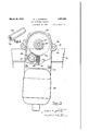
March 29, 1932. H. JOHNSTON 1,851,584
FOOD HANDLING APPARATUS Filed April 18, 1930 2 SheetsSheet 1 Fig. 1
11v VENTOR 5 J ATT0RNEY March 29, 1932. I JOHNSTQN I 1,851,584
FOOD HANDLING APPARATUS Filed .April 18, 1930 2 Sheets-Sheet 2 11v VENTOR M A TTOR/VEY Patented Mar. 29, 1932 COMPANY, or .TROY, 0310,
1 ooRroBA'rIon or oHIo' noon mnprme ArrAnA'rUs I Application fiia April 18,
This invention relates to food handling'apparatus, and particularly to ice cream freezers and driving means therefor,
One of the principal objects of the invention is to provide'a foodhandling apparatus, such as anice cream freezer, of simple construction, having a readily detachable motor drive which is easily and quickly inserted in place and supported in effective drivingrelation with movable freezer parts. v
Another object of the invention is to provide a compact self-contained motor drive unit which is light in weight, is simple in construction, which may be interchangeably used on different kinds of'food handling apr paratus, which may be quicklyand easily inserted in place and detached, and which is provided with simple and effective-means for supporting and holding the drive unit in proper operating position. i
Other objects and advantages of the invention will be apparent from the following description, the accompanying drawings and the appended claims. 1
In the drawings, which disclose a preferred embodiment of the invention--' Fig. 1 is a side elevational view of an ice cream freezer embodying the present invention, parts being broken away and insection on the plane of the line 11 of'Fig. 2 to'illustrate the construction thereof; 7
Fig. 2 is a plan view of the device of Fig. 1,;
Fig. 3 is a partial end elevational view of the device of Fig. 1, a portion of the cover of the motor drive unit being broken away to illustrate the construction thereof; and a Fig. 4 is a perspective view of a detail.
Referring to the drawings, in which like. characters of reference designate like parts throughout the several views thereof, thenu meral 1O designates the container or bucket of an ice cream freezer within which a food can 11 of the usual construction issuitably mounted Any. suitable conventional construction of ice cream freezer can be used in accordance with the present invention, so the details of construction of the freezer are not illustrated in greater detail. The inven'-- tion also permits conversion of standard hand-operated freezers, such as smallsize 'the patent to Johnston et'al. 1,492,468, dated 7 1 Apr1l'29, 1924, may beused. Asillustrated n thedrawin'gs, the. food can,,11is-pro-vided 1930. Serial no, 445,321,
UNITED {STA-T Es PATENT OF CE,
HERBERT L. JOHNSTON, on rnoYjomo, Assr ma 'ro if'r'HE Bonner MAnUrAcrnnme domestic freezers, to power driven freezer-sh 1H3, simpleand highly effectivemanner. As I an 'e ample of a freezer construction to which themvention may be applied, that shown'in with a removable cover 12; having a gear 13 attached thereto, and adapted to m eshwithand be driven by a gear l mounted one c0: rotatable cross shaft 15. Thecrossshaft 15 is j ournalled at '16 within a yoke orizvcross frame 17 which is removabl-y attached to the housing 10 of the freezer. i
As shown, the yoke frame 17, extends: across and is supported ilpon the top of bucket-1d At one side, the bucketlO-is provided with upwardly extended spaced lugs 18 bolted at 19 to the sidewall of the bucket.- Adjacent the upper ends of, the lugs18 are shortinwardly extending circularpins 20 which are mounted in alignment and spaced sutficiently to permit the passage of shaft 15 'therebetween: The yoke frame 117 carries at [this end 'an outwardly extending flange 21 which is substantially rectangular in cross-section, this flange'being adapted to'be inserted when the yoke frame is held'inan upwardlyinclined position between the lugs18,,the.Q'p- I posite side edges of the flange underlying the pins 20; With the flange'21 thus inserted in position, the yoke frame is thenlowered about this mounting as a pivot, caregbeing-taken to properly center the upper protrudingtend 28 of the freezershaftQ l: withinia suitable socket 25 carried by-the "central portion 26 of the yoke frame 17. The freezer shaft24e ex} tends within the food can"; 11, and (carries as'are customarily "provided in freezersof therein suitableiblades, paddles or scrapers l this character." .Thel'can '11 is rotatably mounted in a suitable centering lowerxbearj With the endT23 of shaft 24t properly ceni 1 ing, and is adapted toberotat'ed by theinterteredwithin socket 25, the yoke :fr'ame117 may then be further: lowered about the piv otal mounting 181 until the oppositeuendflr -35 co'rdance with this invention areadilyidetachable power actuated 'drlving means 1s of the frame 17 contacts with the top of vbucket at an area diametrically opposite I lugs 18. The yoke frame 17 is provided at this end with an outwardly projectinglip 29, and a latch pivoted at 31 to the side wall of bucket 10 is adapted to swinginto a position overlying-this lip 29, the latch hav wing acam surface 32 which engagesthe lip f andcams it downwardly into fixed position.-
During this lowering movement'of theyoke frame,the flange 21 slides further in under the pins 20, until the final camming action vof the latch 30 forces a curved surface 33 on the upper side of flange 21 into engage ment with the pins 20,,so that the flange 21 -is wedged in between the top of bucket 10 and the pins 20. The yoke frame isthus provided for rotating the shaft 15 comprising a motor drive unit supported by the ex- ,ten'ded end portion 34 of the shaft 15. A
connecting memberor spline 35 having 'a polygonal cross-section,' such as the herrago nal shape shownmore particularly in Fig. 4,
has a circular threaded bore 36 received upontheshaft portion-34i Cooperating with this member 35 and adapted to slide thereon is a motor drive unitcarrying a sleeve 37 provided with a bore similar in shape to thatof-the-outerdriving surface of the member 35. I This sleeve 37 ismounted for rotational movement within the housing 38 whichmay' be anintegrally extending part of the casing of- -the electric motor 39. The armature 40 "of the motor has'a shaft 41 which is rotat- 'ably mounted within the frame 38 in suit-' ablebearings 42; The shaft 41- carries at its outerend'a worm 44 which meshes with a worm gear 45 which is suitably fixed to a rotatable cross shaft 46. One end of shaft 46 supported in a bearing 47 provided in rthe housing 38, and theother end is supported in a bearing 48 carried by a cover --plate 49 removably attached to'the housing 38- by the; screws 5 0; There is also fixed to ,1 'shaft 46 a spur gear 51"which mesheswith a:
{Rotational movement of'the motor armatime 40 is transmitted through the int'e'rmesh .ing gears which form a reduction gearing to the sleeve 37 'which inturn drives the freezershaft- 15. The'housing 38 isprovided with outwardly extending lugs 58 into which are ,fitted holding means such as, the pins '59 which overlie the topedgeGO of the bucket -10'when;the motor is in its mounted position on the shaft 15" tdprevent rotation of the motor unit about the shaft 15 when themes tor driveunit islin'operation. Tn assembling the motor drive unit for operation on a freezer, the member; 3511s first screwed onto tion is limited by engagement of the member 35 with the shoulder 62 at-the endof the threads. The drive unit-is then slid onto the driving member andthe freezer is then'ready provided with.- conventional electrical 7 leads inan insulated cable (not shown) with a plug the threaded end ofshaft' 15 until this ac 28 V in attachment, so that it can be connected to a house line.
the easy conversion of the usual hand-operated domestic freezers now on the marketto amotor operated freezer Such freezers-are generally provided with a top drive shaft which extends beyond the side of the bucket of the freezer, such as the shaft '15 orthe,
"illustrated construction. The outeinendfof the shaft is generally screw-threaded to 're-- V ceive the usual hand-operated crank. Byv merely removing the hand-operated crank,
. x i The construction describedralso permits inserting the spline35 inplace on this screwthreaded end and then sliding the motor drive unit in place over the spline, the conversion "is accomplished, and the freezer ready for operation as a power j driven freezerl It is obvious that the splii e' 35 may be suitably modified as to the formior diame ter of the internal bore 36 to adapt it to the various shaft endsencountered.
It is to be noted that no special mounting 7 need be'provided for the'motorunit; as it isj effectively supported on the extended-shaft end of the freezer, the motor being suspended from this shaft end along the sidewall ofthe bucket 10 so that'substantially no additional f room isneeded for. theoperation of the freez-- erj and no additionalmodification of the 7 freezer'is necessary. The simplicity of the construction "enables the average domestic user to easily make the changewithout the aid of special toolsor specialized labor. The vertical positioning of the lugs 58 and f pins 59xwithrelation' tothe axis of, the shaft'15 13o is such as to'permit the insertion of the pins for motor operation. The motor unit maybe {9 V between the axis of shaft and the top edge 60. This distance may vary somewhat for different freezers, the one shown in the draw mg being for a small clearance. Where th1s.
distance is greater than the minimum distance, the pins 59 will then clear the top edge 60 by a greater amount; the operation of the motor unit will then set up a torque which will rotate the unit slightly about thesleeve 37 until one of the pins 59 contacts with the edge 60 to limit this rotative movement, the motor then operating in this slightly inclined position, as is clearly illustrated in Fig. 3.
The motor unit is thus made practically universally applicable to food handling apparatus having a containerorframe, with a drive shaft mounted somewhat above the frame and extending outwardly beyond the end of the container or frame, so that the drive unit may be slipped on the end of the shaft and supported in operating position thereon, the motor casing being held against rotation thereon by inter-engaging surfaces between'the casing and frame or container. Proper allgnment of the drlvmg connection betweenthe motor unit shaft and the con-:
tainer shaft is secured by the substantial engaging surfaces between theflspline and The motor unit may be made motor and the reduction gearing. The reduction gearing is designed to give a substantial speed reduction, so that conventional avallable motors can be used to obtain a proper rotative speed of the freezer shaft 15.
lVhile the motor drive unit in actual operation generally shows no tendency to work off of the spline 35, suitable means may be provided ifdesired for positively retaining the unit in operating position; 'One suitable form for accomplishing this comprises pro-- iections or cylindrical enlargements 65 on the ends of pins 59, so that the projection'on the pins 59 which bears on the upper surface 60 of the freezer bucket during operation will engage the interior wall of the freezer bucket upon movement of the freezer unit away from the bucket to thereby positively restrain further movement of this character. In such case, sufficient clearance aboveqthe top of the freezer buclretis provided. for the pins 59,.
so that the projections will clear the up per surface 60 when the motor drive unit is inserted in place on the spline 35. V
-While the form of apparatus herein described constitutes a preferred embodiment of the invention, it is to be understoodithat the invention is not limited to this precise form of apparatus, and that changesmay be made" therein, without departing fron the scope of. I
the invention which is defined in the appended'claims. r v
Whatis claimed is:
ter described,.comprising in combinatioma container, a member adapted .to be driven within said container, a shaft in driving interconnectionwith said member, a non-circutor drive unit removably supported on said shaft, said unlt having a drivmg sleeveof a gagement.
'2. Food ter described, comprising in combination, a
container, a member adapted to be driven; within said container, a shaft in driving in LFood handlingapparatus of the charachandling, apparatus of the characterconnection with said member, a'circular' end portion on said shaft, a splined member rigidly mounted on said shaft end and havmg a polygonal driving surface, a motor drive unit having a driving sleeve with a;
bore corresponding in shape to and adapted to be received on said splined member in driving engagement with said splined memher and shaft, said motor drive unit beingsupported on said shaft end. g
3. A freezer of the character described, comprising an outer container, an inner container, a cross shaft, a driving interconnection between the inner container and the cross shaft to rotate the inner container, aprotruding end on said cross shaft, a splined member mounted. on the protruding end-of said cross shaft, a motor drive unit having a driving 4. For use with food handling apparatus of the character described having a container andadriven shaft; a motor drive unit comprlslng a, motor, a casing therefor, a sleeve mounted 1n sa1d caslng andadapted to re-" ceive said driven-shaft in'driving engagemerit, a driving'mterconnection between sa1d motor and said sleeve including a reduction 1 gearing, said motor drive unit being adapted to besupported from said driven shaft, and means carriedby saidmotor drive unit adapted to engage acooperating part of said con-- tainer to preventrotation of the motor drive a unit about the shaft during the driving of i said shaft by themotor drive unit.
5. For use with food handling apparatus of the character describedahaving a container" and a driven shaft supported above .theupper edge of said container, said shaft having an end extending beyond theperiphery of said container; a motordrive unit removably suslar member mounted on said shaft, and a moll sleeve with a bore corresponding, in shape to 9? pended fromisaid protruding shaftend in driving engagementtherewith, and a project'- iii) ing member carried by said motor drive unit and overlying the upper edg'e of: said container to prevent rotation of themotor drive i 5 'unit about the shaft during theidriving of r said I shaft by the motor drive: unit. 7
.- In testimony whereof I hereto aflix my sig-- natured I "HERBERT LJOHNSTONQ
Priority Applications (1)
| Application Number | Priority Date | Filing Date | Title |
|---|---|---|---|
| US445321A US1851584A (en) | 1930-04-18 | 1930-04-18 | Food handling apparatus |
Applications Claiming Priority (1)
| Application Number | Priority Date | Filing Date | Title |
|---|---|---|---|
| US445321A US1851584A (en) | 1930-04-18 | 1930-04-18 | Food handling apparatus |
Publications (1)
| Publication Number | Publication Date |
|---|---|
| US1851584A true US1851584A (en) | 1932-03-29 |
Family
ID=23768467
Family Applications (1)
| Application Number | Title | Priority Date | Filing Date |
|---|---|---|---|
| US445321A Expired - Lifetime US1851584A (en) | 1930-04-18 | 1930-04-18 | Food handling apparatus |
Country Status (1)
| Country | Link |
|---|---|
| US (1) | US1851584A (en) |
Cited By (1)
| Publication number | Priority date | Publication date | Assignee | Title |
|---|---|---|---|---|
| WO2019197155A1 (en) * | 2018-04-11 | 2019-10-17 | Arcelik Anonim Sirketi | A cooler comprising ice-cream making machine |
-
1930
- 1930-04-18 US US445321A patent/US1851584A/en not_active Expired - Lifetime
Cited By (1)
| Publication number | Priority date | Publication date | Assignee | Title |
|---|---|---|---|---|
| WO2019197155A1 (en) * | 2018-04-11 | 2019-10-17 | Arcelik Anonim Sirketi | A cooler comprising ice-cream making machine |
Similar Documents
| Publication | Publication Date | Title |
|---|---|---|
| US2794627A (en) | Blender | |
| US3783770A (en) | Stirrer devices for culinary purposes | |
| US2162400A (en) | Removable motor mount and adapter for mixers, churns, and the like | |
| US2513254A (en) | Kettle scraping unit | |
| US1851584A (en) | Food handling apparatus | |
| US2372862A (en) | Power unit for food processors | |
| ES2208142T1 (en) | MOTOR UNIT FOR A BOAT. | |
| US2527969A (en) | Novelty turntable | |
| US2017116A (en) | Agitating apparatus | |
| US2028282A (en) | Power unit | |
| US1693170A (en) | Mixer | |
| US1602060A (en) | Machine for making frozen confections | |
| US2074708A (en) | Motor driven mixer | |
| US2031770A (en) | Kitchen utility device | |
| US2639451A (en) | Portable glass washer | |
| US1856631A (en) | Turbine and attachment therefor | |
| US2269859A (en) | Thermometer mercury reducer | |
| US2156770A (en) | Lubrication system for drive mechanism | |
| US1917821A (en) | Pump | |
| US2181089A (en) | Ice cream freezer | |
| US1082243A (en) | Mixing device. | |
| US1814154A (en) | Motor operated dispensing pump | |
| US3695051A (en) | Automatic ice cream freezer | |
| US2560816A (en) | Valve grinding machine | |
| US1880021A (en) | Accessory unit for domestic freezing apparatus |