US1851577A - Friction shock absorbing mechanism - Google Patents
Friction shock absorbing mechanism Download PDFInfo
- Publication number
- US1851577A US1851577A US363583A US36358329A US1851577A US 1851577 A US1851577 A US 1851577A US 363583 A US363583 A US 363583A US 36358329 A US36358329 A US 36358329A US 1851577 A US1851577 A US 1851577A
- Authority
- US
- United States
- Prior art keywords
- friction
- members
- wedge
- casing
- follower
- Prior art date
- Legal status (The legal status is an assumption and is not a legal conclusion. Google has not performed a legal analysis and makes no representation as to the accuracy of the status listed.)
- Expired - Lifetime
Links
- 230000035939 shock Effects 0.000 title description 15
- 238000004873 anchoring Methods 0.000 description 4
- 238000007906 compression Methods 0.000 description 3
- 230000006835 compression Effects 0.000 description 2
- 229920000136 polysorbate Polymers 0.000 description 2
- 241001323275 Andex Species 0.000 description 1
- NVNLLIYOARQCIX-MSHCCFNRSA-N Nisin Chemical compound N1C(=O)[C@@H](CC(C)C)NC(=O)C(=C)NC(=O)[C@@H]([C@H](C)CC)NC(=O)[C@@H](NC(=O)C(=C/C)/NC(=O)[C@H](N)[C@H](C)CC)CSC[C@@H]1C(=O)N[C@@H]1C(=O)N2CCC[C@@H]2C(=O)NCC(=O)N[C@@H](C(=O)N[C@H](CCCCN)C(=O)N[C@@H]2C(NCC(=O)N[C@H](C)C(=O)N[C@H](CC(C)C)C(=O)N[C@H](CCSC)C(=O)NCC(=O)N[C@H](CS[C@@H]2C)C(=O)N[C@H](CC(N)=O)C(=O)N[C@H](CCSC)C(=O)N[C@H](CCCCN)C(=O)N[C@@H]2C(N[C@H](C)C(=O)N[C@@H]3C(=O)N[C@@H](C(N[C@H](CC=4NC=NC=4)C(=O)N[C@H](CS[C@@H]3C)C(=O)N[C@H](CO)C(=O)N[C@H]([C@H](C)CC)C(=O)N[C@H](CC=3NC=NC=3)C(=O)N[C@H](C(C)C)C(=O)NC(=C)C(=O)N[C@H](CCCCN)C(O)=O)=O)CS[C@@H]2C)=O)=O)CS[C@@H]1C NVNLLIYOARQCIX-MSHCCFNRSA-N 0.000 description 1
- 108010053775 Nisin Proteins 0.000 description 1
- 229940000425 combination drug Drugs 0.000 description 1
- 239000004309 nisin Substances 0.000 description 1
- 235000010297 nisin Nutrition 0.000 description 1
- 108010085990 projectin Proteins 0.000 description 1
- 230000003578 releasing effect Effects 0.000 description 1
- 238000000926 separation method Methods 0.000 description 1
- 239000007787 solid Substances 0.000 description 1
- 238000010257 thawing Methods 0.000 description 1
Images
Classifications
-
- B—PERFORMING OPERATIONS; TRANSPORTING
- B61—RAILWAYS
- B61G—COUPLINGS; DRAUGHT AND BUFFING APPLIANCES
- B61G9/00—Draw-gear
- B61G9/04—Draw-gear combined with buffing appliances
- B61G9/10—Draw-gear combined with buffing appliances with separate mechanical friction shock-absorbers
Definitions
- Each springmember pref erably comprises a relatively light innercoil and a heavier outer coil. As most clearly shown in Figure 3, thetop and bottom flanges.
- theblocks'C will be "forced; of saidfriction' members, said 'wedgesmean to slide lengthwise,onthefrictionsurfaces of being movable-lengthwiseEwith respectto the; i the m mbers B, i1hel8l greatly augmenting-wfrictiond memberspsaidw followers having" 10'.
Landscapes
- Engineering & Computer Science (AREA)
- Mechanical Engineering (AREA)
- Vibration Dampers (AREA)
Description
- March 29, 1932. s. a. HASELTINE 1,851,577
FRICTION SHOCK ABSORBING MECHANISM I Filed May 16 1929 51' we; 13m Mark employed in connection iWit-h Patented Mar. 2 9, 1932 o name-mow sHooK: ABS
This' invention relates to improvementsriggings,Jinc1ud-ing a pair oflongitudinally disposed frietion 1 members, means for yield i ing'lyopposing l ateralapprozich' of thefric tion members", friction Wed-ge means eoopersting with the friction"surfivoes-of the 'fri'c tionmembersend' means for Wed-ging the friction Wedge means laterally;- inward 1y againstzmd also longitudinally ofthe friC-f tion members, thereby prov'iding'high cap'ac erating wedgefaoes and the mechenisni.- Q 7 1 A more specific obj ect of :the invention is to provide a friction shock absorbing mohzfl friction surfaoesvof a pair of longitudinally 'clisposed fricti0n"="- members j laterally movable with respect-"to each other; spring res-ist encenneans opposing laterzil epproaoh of" the "friction members;
hers ancl n edge meansaetnated by relati e approach of I the} followers for forcingthe? friction Wedgeb10eks '1aterfl1y inwardly against-the friction members-thereby 60in pressing the spring res'istanc'e and a31s0-forc ing' the wedge blocksto' slide"lengthwise-of the-'i' rietion' SL1I' fajC8S"0f"th frietion-meinf bars toprdducefriotionat resistance;-
Other ohjeots of-the inventionwi l-1 I nore clearly l appear *fr'onr the description I and claims hereinafter following.
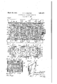
In the drawings, forming part ofthis specifi'ci'tion, Figure '1' is a horizontzrh l ongi tudina-l' sectional "View throu gh the "under frame structure of'a ra'flwlay'car', atone end of the sanie i-lhistrating improvements"infeonnection thereWit-hi Figure-Qis shaman-5 tal, longitudinal; sectional View eor'r'esponding substantially to" the 1i1ie-2-2 of Figure 1. Figure 3 isa transyerseyvertiah sec-" tionzvl' View corresponding *substzintia liy to' the line 3-3- of Figure- 2 Arid Fi gure'Zlfis" 21 detailed" perspective?" 'view of mew STACY 2B. n snmmngwon CHICAGO; lLL'mo sg-Assmnon :mo' w CHICAGO,'-ILLINOIS;Aw'QOR'PORiAEION oF-nmmwim,
nel-sh'zipeicl een terf'of anism specially adapted for-railway draft posed within ity' friotional resistance on the Various mop-*- nismineliiding relatively movable followers; 'of si-1ni1ai'flesifgn; e
friction-wedge b'l ooks 'niovzible' longitudinally" of the mechanisin'elongthe friction meinP;
"casing" A,th"ej innei'fafc'es "off the sections 1 y offset with respect pm the" oute the endiw'al'l"16" and-Tate reintoreed"b at the p mmi "fl-owe {thereby p evi V omit-Ne mmmmm- 7 1 29; see-i m ae s smj 7;
sill'shlO i M'"iinprevedf friet oii sh madly rontfj65 main springlresis'tanceE bolts 4 ,'F- and an line The. front i-ntl" lie" pairfof stop lugsiofth outer "end walli '16, s gced top a d *ziiitLsjbzi-eeWsid "Wall's 8 The sidewalls 18 have outwar d-lyidwerg n presentiingfopposedfiedge'fia es 20%204'1 Th mal n portions oft-he sidew ls ls a e.
zontally flex-tending Web 'l h'ei e provic e yv ith" a p a; tically disposed interimribs 21-5-21 if) accommodate th B Bereoes-imii designand are arranged on oppositesides of the mechanism. Each member B is provided with top and bottom inwardly projectin -horizontal flanges 2626 and vertical end flanges 27-27. On the outer side each member" B presents a, longitudinally disposed flat friction surface 28. The friction members B are'of su'ch' a length that the opposite ends thereof extend into the front and rear follower casings Ain the normahfull release position of the parts. It is-further pointed out that these members are of such a length 7 that the 'oppositeends will'be engagedby the ;end Walls of the casings A when the mecha- I nismis fully compressed, thereby limitingrelative approach of the follower casings.
Ea'ch'fof the friction members B is provided with openings 29 29 at. opposite ends theref adapted to receive the anchoring element G. jfThemembers B are anchored to the rear follower casing A as shown in the present instance,'the' same being connected to the easing by the anchoring element G, which is in the form of a bar of substantially rectangular cross section. As shown, the member G extends. through the openings 23, ofthe side walls L of the rear follower casing A, the openings '29 of. the'members B, andjhas the intermediate portion thereof seated in the v,notches'22'of the casing. As will be evident, the members'Bf may be secured to the front follower casinghinstead of to the rear f0l-' lower casing by making use of the openings -29 at the forward ends of the members B and the openings 23 of the casing A.
The friction wedge blocks" CJ-C are simivlar designjandjarearranged'in pairs at the I front and rear endsof the mechanism. The members of each pairoffriction, wedge blocks a I C are disposed on opposite sides of the pair (if longitudinally disposed friction members B B. Each block C has a rlongitudinally, extending flat surface 30 which cooperates with the frictionhsurface 28 of. the friction] member 'B' at the same side of the mechanism. on the, outer side each block C, is pro vided with front and rear'wedge faces 3131 The'wedgejface '31'atthe outer end of'each' blockengages the wedge face 20 at the cor wedge face 31 of1each block G'cooperates with responding sideof; the follower casingA at the same 'end'of the mechanism. The other the central wedge casingiD."
. The central wedge casing Dis theformQ of a rectangular sleeve having spaced top and bottom: walls .'32'32 and vertical side walls 33+33. Asshown'thesleeveD is open at the front and rear endsand has the friction mem-v ber' s B extending"therethrough. Each ofjthe side walls339f thecasing is provided with 'interioriwedgefaces 34%34 at opposite ends thereof. @The wedge faces 34 at each end of thejc'asing Dareopposed and diverge outwarclly of the mechanism. The wedgegfaces 4 at the. front and rear .ends of the. casing engage the-wedge faces 3131 of the front and rear wedge blocks at the same side of the mechanism. As shown, the wedge blocks C are of such a length that the opposite ends thereof extend into the casing D and the front and rear follower casingC sothat the wedge blocks are supported bythe casing and the front and rearfollowers in all operative positions of the parts.
The; main spring "resistance .15], whichiis o interposed-between the two friction members BB, preferably; comprises three spring member's extending transversely of the mechanism and having their opposite ends bearing on't-he inner sides of the vertical walls of the ;members B. Each springmember pref erably comprises a relatively light innercoil and a heavier outer coil. As most clearly shown in Figure 3, thetop and bottom flanges.
26 0f the members B overhang the'ends of the springs, thereby holding the same in. proper 7 position and maintaining them assembled with the mechanism. The inner sides of the vertical walls of the members B are preferably reinforced by'webs35 35 which also serve as spacing meansfor thespring members as clearly shown in Figure 2. j, V The retainer bolts FF are preferably two in number and are arranged at thetop and bottom of the mechanismabove and below the sprlng resistence'E. The bolts F extendf through the'centr'al casing D and alined openthe nut at the opposite end thereof abutting the wall 25 of the front follower casing. As shown,.the head and the nut of each bolt is accommodated within the correspondingcut; awayportion 2 f of-the followerA, thereby allowing for the necessary relative movement e of the followercasings A and the bolts dur g y ing thecompression 0f the mechanism.
In addition to holding the mechanism assembled, theretaining bolts F also main-' @tain the mechanismof uniform overall length. 1 {The bolts are preferably so adjusted when the V mechanism is assembled that the main spring 'i1'1gs in the front and rear follower casings A, g each bolthaving the head thereof abutting the wall 25 of the rear follower casing and resistence E is under initial compression,
thereby compensating for wear of thevarious V wedge faces and friction surfaces of the mech.-
aIllSIIl.
' In theoperation 'of my improved shock absorbing mechanism when either .bufling or draft force is applied, the follower casings A will be, moved relatively inwardly toward each other. During relative approach ofthe follower casingsA, awedging action will be it set up. between.v the same and the friction iwedge blocks C. At the same timedueto. the
inward movenientof um blocksC, a wedging action will'be setupbet'ween the latter. and the wedge casing lTheblocks C at oppos, L site sides ofthe mechanism willjthusbe forced V laterally inwardly toward each other, thereby forcing the longitudinally disposed fric- 2.1Inaa friction: shock;:absorbing jHlQ'GlIH. tron membersB-B laterally inwardlyto nisnr, thewcombinati on with front' 'and: rea ward each other also and compressing thefollowers relatively 'movabl'ea toward and;-v main spring resistance E. i During the move awa'y from each other; of longitudinally dismentof the casings A toward eachxother while- 1 posedwfrictionwmembers linterp'osed' b'etwe 7 effecting lateral inward wcdgingacti-on on the "saidwfollowers 'y-wedge meansiat opposite sides wedge blocks C, theblocks'C: will be "forced; of saidfriction' members, said 'wedgesmean to slide lengthwise,onthefrictionsurfaces of being movable-lengthwiseEwith respectto the; i the m mbers B, i1hel8l greatly augmenting-wfrictiond memberspsaidw followers having" 10'. the re tance of the mechahism-,. due toithe wedging engagement with theawedge means; friction thus-produced. Theicompressi'onof,andspring,resistance means interposed be the mechanism will continue until the front tween said-friction members'opposingrlateral ends of the friction members-Bare;eng ged approach-of thei'same. i i by. the end wall 16 of the -fro-nt'f0llower- I 3. In a friction shock"absorbingnmecha casi ri, whereupon the members -13 iwillwrnism,thezcombination with lateral inwardly limit the relative approach of the followenacting Wed e' members,1nclnd1ng'frontl'and casings and prevent ;.e:;cessi-ve-compression rear;afollower-zelementsi and a central" casing: of the main spring'resistance E, L-As will, be elementgof-a pair. of longitudinally-disposed evident, the two members-Btogether form a friction members anchored to oneofz saidre'le- 29 solid coluinload:transmittingmember,when ments; against relativewlongitudinal mover-i the mechanism is fully compressed,transmits ment but-havinglateralmovement withiree' ting the actuating" force from one follower specti thereto; springresistance meansiyield directly to theotherandtothe step'l-jugsgofwingly; opposing relative'gapproach ofsaid the draftsillsc v 1 I members; and. friction wed-gecblocks at bpi A 25 During release of the mechanism,theaex posite sides of said members cooperatingnil pensive action of tl18l11illHS-PYiHg resistancewwitlnsaid elements and wedged' laterally, in; E will force the'friction memhers B+B lat-v wardly thereby upon-relative approach .of-u erallyapart, carrying the wedge bloclrs=C+G- said "followers; saidblocksehavingaa sliding-, therewith. Dueto the-lateralseparationof engagement with-thevfrictionumembersfi v 30 the wedge blocks-C Gat opposite sides of tln a friction shock absorbing. 1'Ine'ch'a the necha nisnnthe front andzifear-followerqnismgithe combinationkwithifront!zand 'rear casings A will be wedgedapart and; restored followers of-a pair ofi'longitudinally"disposed to the normal full release position, outward: -friction-membe-rs laterallyrmovable towar movement of the casingscbeing limited bythe and awaygf-romeach other, spring; resistanceretainer bolts its willbe evident, during meanssopposingwlateral approach of iesaidwl the releasing action; ofH-the"mechanism,the members meansf-or :holdingi-saidm memefriction members B Willabe heldag-ai'nstdon? bers? against-movement flen-gthwise -of" :onci gitud-inal movementwith respect to the rear -of said afollfowers; friction -.wedge;n means follower 'casingii by the anchoring element-at opposite sides of said members, including G. Vhile the anchoring element Q prevents a plurality-ofelements, certain of-whiohahav'e' relative lengthwise movementof the -frictionn frictionalengagement-with said. members a members B and the, reari-followerfcasing.A, are forced laterally inwardly upon relative the same permits free, lateral approach approach ofsa-idfollowers; F
and separation of thesemembers. 7 5.141 a (friction "shock-absorbing mechaw- I 45. I h he in hownanddescribedwhat I jnismgg the*combination--withfrontzandrear nowcbnsider'the preferredmanner of carryfollower eas-ings,Leachhavingopposedainterior 11 ing out my invention, but the same is merely wedges faces of floating casing interposed ilnstrative and}: contemplate all changes and between said-followers, aidvcasinigl :havinga; 'modificationsthat come within the scope of sets-0 f opposedinterior wedgeifaces atvoppo theclaims 'appendedhereto; l site'endsthereof;apaia: o-f longitudiinallyrdiss I claim: j- V V posedfriction?membersinterposedbetween v 1. In a friction shock absorbing" mecha saidfol-lowersa-ndlextendingthroughithecas s, nisin', the combination with front' and-rear inggrspringresistance means-interposed?been follower acting means; ofra' pair-*oflongi tween theflfriietionmembersopposingirelatixze tudinally'disposed friction members? means approach refine-same, and :front and-rear interposed between said members-opposing pairs-bf frietion wedge blocks at :opposite" lateral approach thereof wedge; means atInsicleseof said;memberseand liavingifrictionv opposite sides ofsaidw members, incl-uding'ra engagement therewith, b ti P 'W lg plurality of members, certainof which have blocks thawing; wedging engagement: with; the
f frictional engagement with: said SlClGi'IYlGHP- wed e facesat oneend'of the casingwandzwith hers and wedging engagementwith thefront-:- 3 edge faces ofone of sald follower cas and rear followers, whereby the last namedv a, V a i a a i- Wedge members are forced laterally inwardly I (i. iIni'a friction shock absorbingegmech'a upon'relativ-e approach of said vfollowers and nisin-,the combin ation withzfrontjandrear-fol 55 moved lengthwise of theimechanism; is lowersrelatiyelyi novable:toward andaa way from each other; of a pair of longitudinally disposed friction -members interposed between said followers; means yieldinglyopaposing'lateralapproach of said friction inembers; wedge friction blocksat opposite sides of saidmembers having frictional engagement therewith and wedging engagement with one ofsaid followers; and means oppossing lateral outwardmovement of said blocks. I 7. In a friction shock absorbing mechanism, the. combination with front and rear followers; of apair-of longitudinally dis posed friction members interposed between said followers;
"disposed springs a plurality of' transversely and front andrear pairs offriction wedge blocks 'at opposite sides'of said pair of friction members, 'said 'blocks being-slidable on the friction members,
each pair of wedge blocks having wedging follower casings, having laterally inwardly acting wedge/means thereon; of a pair :of. longitudinally disposed, spaced friction memhers, said members bein'g laterally movable with respect to each other and connected to members and having wedging engagement with the inwardly acting wedge means of the floating casing and front; and rear follower casings.
9. In a friction shock absorbing mechanism, the combination with front and rear followers; of a pair 'of longitudinally disposed spaced friction elements laterally movable toward and awayfrom each other, said elements being engaged at opposite ends by tliefollowers upon full compression of the r 1 a mechanismctolimit relative aPProachof the. the comblnatlon Wlthr front andmearmf" followers, thereby providing a columnmember' transmitting the actuating force from one follower to tlie'othe'r;meansyieldingly opposing lateral approach ofsaidf friction members frictioniblocks between it said fo l-.
' 1 lowers "on; opposite sides of said pair of fric tion sme'mbers and longitudinally slidable thereon a central casing; and wedge means on said followers and easing having wedging engagement with said said friction blocks laterally inwardly against the friction members and and j friction elementsupon relative movehaving longitudinally disposed outer fricinterposed between said'fric-v' tion members opposing relative lateral ap-' proach of the same; a floating central mem- -berembracing saidv pairrof friction members engagement I with one of said followers, and with the floating centralmembery i 8.cIn a friction shock absorbing m'echa nism, the combination with front and rear blocks for forcin V effecting relative longitudmalmovementof said friction blocks each other.
nism, the combination with side members extending lengthwise of the mechanism and tion surfaces; of spring resistance means 0 posing relative lateral approach of said si e members; friction elements ,at-opposite sides of said side members slidable lengthwiseon the friction surfaces thereof; and means havingwedging engagement with opposite ends of said friction elements for wedging the 'same'la'terally inwardly against said side members and forcing the side members toward each other to compress said spring re- 7 sistance. g 11. In a friction shock absorbing mechanism, the combination with front and rear followers; of a-casing disposed between said followers; friction elements disposed-lengthwise ofthe mechanism at opposite sides thereof and having wedging engagement with said followers and easing whereby said memp bers are forced laterally inwardly upon-relative approach of said followers; a pair of side members between said friction elements and having frictional engagement therewith; and
means between said side members opposing" relative approach thereof.
12. In a frictionshockabsorbing mecha-' I nism, the combination with spaced side mem bers extending lengthwise of the media-- nism, and movable laterally toward each other; of spring means opposing relative approach of said side members, said side members having exterior friction surfaces and" friction elements at opposite "sides of the mechanism having v frictional engagement with said side members and'movable lengthwisefthereonf; and means for cwedging said friction elements laterally inwardly, said means including front and rear follower casings having'wedging engagement with said] friction elements and afloa'ting casing interyieldingly posed between said follower'c asings and also 7 having wedging engagement with'said elements.
13.In a friction shock absorbing-mechas follower casings having interior opposedwedge faces; of a floating casing'interposed between said follower casings, said casing having front and rear sets of interior opposed wedge faces; front-and rear-pa rs of friction elements at opposite sides 'oflthe' mechanism,
of the wedge faces of said floating casing; longitudinally extending spaced side mem: bers interposed between said follower cascasing, said side members ments having cooperating friction surfaces ings andex'tending through said floatingQ and frictionele-V i as extending lengthwise of the mechanism; and
spring resistance means opposing *relative lateral approach of said side members.
14. In a friction shock absorbing mechanism, the combinationwith'front and rear follower casings having interior opposed Wedge faces; of a floating casing interposed between said follower casings, said casing having front and rear sets of interior opposed wedge faces; front and rear pairs of friction elements atopposite sides of the mechanism, each of said elements having wedge faces at opposite ends thereof cooperating with a wedge face of one of said followers and one of the wedge faces of said floating casing; longitudinally extending spaced side members interposed between said follower casings and extending through said float-V ing casing and telescoped with said front and rear follower casings, said side members and friction elements having cooperating friction surfaces extending lengthwiseof the mechanism, said friction elements being supported by said front and rear follower casings and said floating casing; and spring resistance means opposing relative lateral approach of said side members.
In Witness that I claim the foregoing I have hereunto subscribed myname' this 15th day of May 1929. I
STACY B. HASELTINE.
Priority Applications (1)
| Application Number | Priority Date | Filing Date | Title |
|---|---|---|---|
| US363583A US1851577A (en) | 1929-05-16 | 1929-05-16 | Friction shock absorbing mechanism |
Applications Claiming Priority (1)
| Application Number | Priority Date | Filing Date | Title |
|---|---|---|---|
| US363583A US1851577A (en) | 1929-05-16 | 1929-05-16 | Friction shock absorbing mechanism |
Publications (1)
| Publication Number | Publication Date |
|---|---|
| US1851577A true US1851577A (en) | 1932-03-29 |
Family
ID=23430796
Family Applications (1)
| Application Number | Title | Priority Date | Filing Date |
|---|---|---|---|
| US363583A Expired - Lifetime US1851577A (en) | 1929-05-16 | 1929-05-16 | Friction shock absorbing mechanism |
Country Status (1)
| Country | Link |
|---|---|
| US (1) | US1851577A (en) |
-
1929
- 1929-05-16 US US363583A patent/US1851577A/en not_active Expired - Lifetime
Similar Documents
| Publication | Publication Date | Title |
|---|---|---|
| US1851577A (en) | Friction shock absorbing mechanism | |
| US1741651A (en) | Shock-absorbing mechanism | |
| US1873718A (en) | Friction shock absorbing mechanism | |
| US1605024A (en) | Friction shock-absorbing mechanism | |
| US1515840A (en) | Walter h | |
| US1637149A (en) | Friction shock-absorbing mechanism | |
| US1673372A (en) | Friction shock-absorbing mechanism | |
| US1586322A (en) | Friction shock-absorbing mechanism | |
| US1290221A (en) | Friction shock-absorbing means. | |
| US1870508A (en) | Friction shock absorbing mechanism | |
| US1674873A (en) | Friction shock-absorbing mechanism | |
| US1650380A (en) | Friction shock-absorbing mechanism | |
| US1571681A (en) | Friction shock-absorbing mechanism | |
| US1439803A (en) | dorey | |
| US1904379A (en) | Friction shock absorbing mechanism | |
| US1668901A (en) | Friction shock-absorbing mechanism | |
| US1640214A (en) | Friction shock-absorbing mechanism | |
| US1308965A (en) | High-capacity shock-absorbing mechanism | |
| US1702032A (en) | Draft gear | |
| US1648320A (en) | Friction shock-absorbing mechanism | |
| US1137951A (en) | Draft-gear. | |
| US1679921A (en) | Shock absorber | |
| US1430631A (en) | Friction draft rigging | |
| US1680292A (en) | Friction shock-absorbing mechanism | |
| US799698A (en) | Friction draft-gear. |