US1851576A - Support for machine guns and the like - Google Patents
Support for machine guns and the like Download PDFInfo
- Publication number
- US1851576A US1851576A US551182A US55118231A US1851576A US 1851576 A US1851576 A US 1851576A US 551182 A US551182 A US 551182A US 55118231 A US55118231 A US 55118231A US 1851576 A US1851576 A US 1851576A
- Authority
- US
- United States
- Prior art keywords
- seat
- gun
- support
- swing
- gunner
- Prior art date
- Legal status (The legal status is an assumption and is not a legal conclusion. Google has not performed a legal analysis and makes no representation as to the accuracy of the status listed.)
- Expired - Lifetime
Links
- NIOPZPCMRQGZCE-WEVVVXLNSA-N 2,4-dinitro-6-(octan-2-yl)phenyl (E)-but-2-enoate Chemical compound CCCCCCC(C)C1=CC([N+]([O-])=O)=CC([N+]([O-])=O)=C1OC(=O)\C=C\C NIOPZPCMRQGZCE-WEVVVXLNSA-N 0.000 description 11
- 238000010304 firing Methods 0.000 description 4
- 230000004048 modification Effects 0.000 description 4
- 238000012986 modification Methods 0.000 description 4
- 230000009194 climbing Effects 0.000 description 3
- 210000003128 head Anatomy 0.000 description 3
- 239000000700 radioactive tracer Substances 0.000 description 3
- 230000009189 diving Effects 0.000 description 2
- 230000005484 gravity Effects 0.000 description 2
- 230000006978 adaptation Effects 0.000 description 1
- 230000000881 depressing effect Effects 0.000 description 1
- 230000003028 elevating effect Effects 0.000 description 1
- 230000002349 favourable effect Effects 0.000 description 1
- 239000003381 stabilizer Substances 0.000 description 1
Images

Classifications
-
- B—PERFORMING OPERATIONS; TRANSPORTING
- B64—AIRCRAFT; AVIATION; COSMONAUTICS
- B64D—EQUIPMENT FOR FITTING IN OR TO AIRCRAFT; FLIGHT SUITS; PARACHUTES; ARRANGEMENT OR MOUNTING OF POWER PLANTS OR PROPULSION TRANSMISSIONS IN AIRCRAFT
- B64D7/00—Arrangement of military equipment, e.g. armaments, armament accessories or military shielding, in aircraft; Adaptations of armament mountings for aircraft
- B64D7/02—Arrangement of military equipment, e.g. armaments, armament accessories or military shielding, in aircraft; Adaptations of armament mountings for aircraft the armaments being firearms
Definitions
- LRoY R.GRl/HHAN avwcmtoz Patented Mar. 29, 1932 are LEROY R. GRUMMAN, OF PORT TASI-IINGABON NEW YORK SUPPORT FOR MACHINE GUNS AND THE LIKE Application filed Jul 16,
- This invention relates to gun supports and more particularly to machine gun supports to be employed on military airplanes.
- the means I employ are adaptable to a great number of other uses, such as the mounting of motion picture cameras, telescopes, and other apparatus which requires to be trained upon moving objective. It is not restricted to use in airplanes and may properly find its fullest development in places where space is at less premium than in the cockpit of an airplane.
- This gun may be any of a number of types or calibers depending upon the mission of the plane in which it is placed.
- the gunner was usually obliged to stand and was often forced into awkward and dangerous positions. While standing the force of the slip stream against his body prevented accurate aim and during any acrobatic or aerobatic evolutions he was compelled to cease firing. Even under favorable conditions he was seldom able to sight the gun and was ordinarily compelled to rely on tracer bullets to direct his fire.
- An object of my invention is so to combine the gunners seat and the gun support that the gunner may remain seated at all times with the sights of the gun always in line with his eyes, except at such times as he elects to fire at extreme angles and rely upon tracer bullets to indicate the direction of his fire. Another object is to permit the gunner to fire at extreme elevations without leaving his seat to squat under his gun. A further object is to so construct the entire seat and mount that a minimum target is presented to enemy fire, and a minimum air resistance is caused by the weapon.
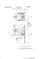
- Figure 1 is a cut away longitudinal view of part of the.
- Figure 2 is a sectional view greatly en larged taken through the anchor plate of Figure 1 at the line 22.
- Figure 3 is a sectional view of my invention taken along the line 33 of Figure 1 looking in the direction of the arrows.
- Figure 4 is a plan view of the invention in place in the fuselage of an airplane.
- Figure 5 is a side view of a modification of my mounting adapted to shoot through a hole in the bottom of the fuselage.
- an airplane fuselage 10 is fitted with a seat 11 shown facing rearwardly.
- This seat is of the conventional bucket type but may be of any suitable kind. It is pivotally mounted in a U frame or swing 12 so that it may turn freely within certain limits with respect to the swing. The turning movement is limited only by interference of ably made a part thereof, projects a socket the seat or of its occupants legs with arms 13 of the swing 12. In a pursuit plane or any fast plane in which the fuselage is necessarily narrow such interference is unavoidable but where space is not at a premium the arms of the swing may be readily constructed to permit unrestricted turning.
- the seat 11 is mounted by suitable means as a worm (not shown), and nut 19 affixed to the swing 12 to prevent it from becoming dismounted when the airplane is flying in a inverted position.
- the swing 12 is'suspended by its arms 13 which are movably pinned by bolts 1 1 to suitable supports such as stanchions 15 preferably part of the supporting structure of the fuselage.
- the swing 12 may oscillate forward or backward through an are having the pins 14 as a center and the arms 13 as radius.
- an arcuate fin 16 is affixed to the floor 17 of the cockpit and on its upper surface is mounted an anchor'plate 18 posltioned to afford a rough working clearance between its surface and the lowermost of the swing 12.
- apertures 20 designed to receive a locking plunger 21 which is movable in a sleeve 22 attached to the exterior of the nut 19.
- the plunger 21 may be raised-or lowered by operation of a hand lever 23 which moves in a slotted uadrant 24, and is connected by suitpoint able lin age 25 to the plunger 21.
- a spring (not shown) may be used to return the plunger to its locking position.
- Suitable clamping means such as nuts 28 are provided on the socket 26 to enable the arm 27 to be firmly clamped therein.
- a suitable fitting 29 At the upper end of the arm 27 is a suitable fitting 29 to receive a machine gun 30 and its conventional mounting 31 which permits free movement of the gun in a wide range of positions.
- the points of support of the arms 13 of the swing 12 are designed to come as nearly as practicable on a line passing through a point slightly above the center of gravity of the seat, its support, its occupant, and the gun and its support.
- the gunner When thus positioned it requires only slight effort of the gunner to swing the seat and gun right or left or to swim the entire ensemble backward or forwar assuming of course that the locking pin 21 has been lifted out of engagement with any of the holes 20 in the plate 18.
- Figure 5 shows a modification which may be usefully employed on some types of fighting airplanes either for offensive or defensive work.
- the arm 27 is made relatively short to readily permit the depression of the muzzle of the gun to an angle which will allow of shots being fired through an opening in the under side of the fuselage (not shown) at an enemy who would ordinarily be in a blind or inaccessible spot. In raking fire upon ground troops without the necessity of diving this type of mounting should be useful.
- the arm 27 is so proportioned as to bring the gun- 30 into such position relative to the gunner that the sights will normally be in line with his eye when he is comfortably seated and the gun held in normally horizontal position as shown in Fi ure 1.
- the gunner takes his place in the seat 11 with his legs on either side of the fin 16 and his feet upon the rungs or steps 32. He is facing the rear and his gun is pointing directly at his vertical stabilizer or rudder (not shown).
- the modus operandi may best be illustrated by assuming certain tactical conditions. If an overtaking target appears to the rear, somewhat below, a little to the right, climbing slightly and considerably out of range, the gunner would swing his seat a trifle to the left to bring his weapon in line with the target, and lift upon his hand grips thereby depressing the muzzle of his gun until it rests upon the top of the fuselage, the limit of its downward movement,
- the target gets above the gunner, he pulls the gun into its most comfortable position, releases the locking pin 21 and pushes on one of the rungs 32 with his foot thereby swinging his seat forward and elevating the muzzle of his gun. He may keep his target covered, his eyes always in linewith his sights by moving the gun on its mount and following with his head for slight variations of position. The overtaking target may get close enough to be afraid of long range shots and begin to zig zag. It can still be covered by movement of the gun on its mount and slight changes of the gunners head position.
- the gunners plane to avoid fire from the pursuer, might zig zag, zoom, dive, or perform other evolutions causing a great relative movement in 'the position of the target,
- the gunner by swinging his seat from side to side and combining the up and down movement of his swing with the side to side movement of his seat is enabled to keep the target covered.
- a target should approach head on, in other words, from the gunners rear, he might learn of its presence from the fire of his pilot and look to see on which side it will pass. He would then turn his seat as far as possible and swing the gun to the practical limit of its sidewise movement. He can not easily look through the sights in-this position and hisaim must :be governed by his observation of the path of his tracer bullets.
- the gunner becomes aware of a target diving upon him from above, he may push himself back to obtain the maximum aimed elevation of his piece, and in this position he may get aimed sidewise play for the weapon by turning the seat in the swing.
- the seat may be swiveled to face forward and the rear cockpit will not differ materially from that of the ordinary tandem two seater. and its support would be dismounted from the seat.
- a swivel seat having a support for a firearm, a swing supporting said seat, and means to enable the occupant'to utilize the swivel and the swing to keep the firearm trained upon a moving object.
- a U frame having side'members and a cross member, a seat rotatably mounted in the cross member between said side members, a
- a U frame having side members and a cross member, a seat rotatably mounted in the cross member between said side members, a support for machine guns and the like affixed to said seat and rotatable therewith, means associated with said side members to swingably suspend said frame and means op- 4.
- a U frame having side members and a For comfort the gun side walls, a U shaped member therein swingable longitudinally thereof having arms pivoted to said walls, a seat pivoted in the base of the U member and rotatable with respect thereto, and a support for firearms and the like extending upwardly and forwardly of said seat.
- a U shaped member therein swingable longitudinally thereof having arms p1voted to said walls, a seat pivoted in the base of the U member and rotatable with respect thereto, a support for firearms and the like extending upwardly and forwardly of said seat, and means to lock said U member in any position in the arc of its swing.
- a frame pivoted in the said walls and swingable longitudinally of said cockpit, a seat rotatably mounted in the base of said frame, a support for firearms and the like rigidly afiixed to said seat, and means controlled from said seat to lock said frame at any point in the arc of its swing.
- a U shaped swinging member pivotally mounted therein, a seat rotatably mounted within the arms of the U memher and swingable therewith, said seat having a forward and upward projection adapted to support a machine gun and the like, and means associated with said seat operable by the occupant to lock the seat in any desired position in the arc of its swing.
Landscapes
- Engineering & Computer Science (AREA)
- Aviation & Aerospace Engineering (AREA)
- Toys (AREA)
Description
arch 1932- R. GRUMMAN SUPPORT FOR MACHINE GUNS AND THE LIKE Filed July 16, 1931 2 Sheets-Sheet NH mm/ *Q L. wm/ wfi 2 4 mm y Y 2 mm 2 3 a LEROY R.G-Runrm1v awoemtoz @3313 his 61mm; M hfma e March 29, 1932. Q GRUMMAN 1,851,576
SUPPORT FOR MACHINE GUNS AND THE LIKE Filed July l6, 1931 2 Sheets-Sheet 2 Fig. 1,
Fig. 5
LRoY R.GRl/HHAN avwcmtoz Patented Mar. 29, 1932 are LEROY R. GRUMMAN, OF PORT TASI-IINGABON NEW YORK SUPPORT FOR MACHINE GUNS AND THE LIKE Application filed Jul 16,
This invention relates to gun supports and more particularly to machine gun supports to be employed on military airplanes. The means I employ, however, are adaptable to a great number of other uses, such as the mounting of motion picture cameras, telescopes, and other apparatus which requires to be trained upon moving objective. It is not restricted to use in airplanes and may properly find its fullest development in places where space is at less premium than in the cockpit of an airplane.
It is in airplanes, however, and with machine guns that my preferred embodiment of the invention is concerned. Military airplanes of the pursuit type have until recently been of single seater design and have been particularly vulnerable from the rear, so much so that the primary battle tactics between planes of this character have hitherto consisted of attempting to get above and behind the enemy plane. The attempt to do this generally results in the opposing planes chasing each other in a spiral with the ultimate .advantage going to the airplane with the greater climbing ability. Such tactics are not tried in combat between a pursuit plane and a two seatef or observation plane which is customarily equipped with a rear firing gun capable of limited motion in lateral and vertical planes. In spite of the heavier armament of the two seater plane in the past it was usually at a disadvantage in combat with a pursuit plane because of the greater speed and climbing ability of the latter.
At the present time, however, owing to improvements in power plant and in aerodynamic design of airplanes it is practicable to build a bi-place plane with all the speed and power of the one place machine, and it is therefore probable that the pursuit plane of the future will be a two seater carrying additional armament in the form of a rear firing gun. This gun may be any of a number of types or calibers depending upon the mission of the plane in which it is placed.
In some of thefighting planes of the past in which a rear firing weapon was used it was mounted upon a ring which framed the gunners cockpit. In order to operate this gun 1931. Serial No. 551,182.
the gunner was usually obliged to stand and was often forced into awkward and dangerous positions. While standing the force of the slip stream against his body prevented accurate aim and during any acrobatic or aerobatic evolutions he was compelled to cease firing. Even under favorable conditions he was seldom able to sight the gun and was ordinarily compelled to rely on tracer bullets to direct his fire.
An object of my invention is so to combine the gunners seat and the gun support that the gunner may remain seated at all times with the sights of the gun always in line with his eyes, except at such times as he elects to fire at extreme angles and rely upon tracer bullets to indicate the direction of his fire. Another object is to permit the gunner to fire at extreme elevations without leaving his seat to squat under his gun. A further object is to so construct the entire seat and mount that a minimum target is presented to enemy fire, and a minimum air resistance is caused by the weapon.
Other objects are apparent or will be referred to hereinafter.
Referring to the drawings Figure 1 is a cut away longitudinal view of part of the.
fuselage of an airpane in which my invention has been installed, taken on the line 1-1 of Figure 3 looking in the direction of the arrows.
Figure 2 is a sectional view greatly en larged taken through the anchor plate of Figure 1 at the line 22.
Figure 3 is a sectional view of my invention taken along the line 33 of Figure 1 looking in the direction of the arrows.
Figure 4: is a plan view of the invention in place in the fuselage of an airplane.
Figure 5 is a side view of a modification of my mounting adapted to shoot through a hole in the bottom of the fuselage.
In the drawings an airplane fuselage 10 is fitted with a seat 11 shown facing rearwardly. This seat is of the conventional bucket type but may be of any suitable kind. It is pivotally mounted in a U frame or swing 12 so that it may turn freely within certain limits with respect to the swing. The turning movement is limited only by interference of ably made a part thereof, projects a socket the seat or of its occupants legs with arms 13 of the swing 12. In a pursuit plane or any fast plane in which the fuselage is necessarily narrow such interference is unavoidable but where space is not at a premium the arms of the swing may be readily constructed to permit unrestricted turning. The seat 11 is mounted by suitable means as a worm (not shown), and nut 19 affixed to the swing 12 to prevent it from becoming dismounted when the airplane is flying in a inverted position. I
The swing 12 is'suspended by its arms 13 which are movably pinned by bolts 1 1 to suitable supports such as stanchions 15 preferably part of the supporting structure of the fuselage. The swing 12 may oscillate forward or backward through an are having the pins 14 as a center and the arms 13 as radius. In order to prevent a swinging motion where none is wanted an arcuate fin 16 is affixed to the floor 17 of the cockpit and on its upper surface is mounted an anchor'plate 18 posltioned to afford a rough working clearance between its surface and the lowermost of the swing 12. v
At spaced intervals along the plate 18 are apertures 20 designed to receive a locking plunger 21 which is movable in a sleeve 22 attached to the exterior of the nut 19. The plunger 21 may be raised-or lowered by operation of a hand lever 23 which moves in a slotted uadrant 24, and is connected by suitpoint able lin age 25 to the plunger 21. A spring (not shown) may be used to return the plunger to its locking position.
Out of the base of the seat 11, and prefer- 26 adapted to receive an arm 27. Suitable clamping means such as nuts 28 are provided on the socket 26 to enable the arm 27 to be firmly clamped therein. At the upper end of the arm 27 is a suitable fitting 29 to receive a machine gun 30 and its conventional mounting 31 which permits free movement of the gun in a wide range of positions.
Preferably the points of support of the arms 13 of the swing 12 are designed to come as nearly as practicable on a line passing through a point slightly above the center of gravity of the seat, its support, its occupant, and the gun and its support. When thus positioned it requires only slight effort of the gunner to swing the seat and gun right or left or to swim the entire ensemble backward or forwar assuming of course that the locking pin 21 has been lifted out of engagement with any of the holes 20 in the plate 18. To assist the gunner in maneuvering his seat I have provided rungs or foot rests 32 within easy reach of his feet and he will find Figure 5 shows a modification which may be usefully employed on some types of fighting airplanes either for offensive or defensive work. In this modification the arm 27 is made relatively short to readily permit the depression of the muzzle of the gun to an angle which will allow of shots being fired through an opening in the under side of the fuselage (not shown) at an enemy who would ordinarily be in a blind or inaccessible spot. In raking fire upon ground troops without the necessity of diving this type of mounting should be useful.
It is hardly necessary to point out that in the preferred form the arm 27 is so proportioned as to bring the gun- 30 into such position relative to the gunner that the sights will normally be in line with his eye when he is comfortably seated and the gun held in normally horizontal position as shown in Fi ure 1.
' n operation the gunner takes his place in the seat 11 with his legs on either side of the fin 16 and his feet upon the rungs or steps 32. He is facing the rear and his gun is pointing directly at his vertical stabilizer or rudder (not shown). The modus operandi may best be illustrated by assuming certain tactical conditions. If an overtaking target appears to the rear, somewhat below, a little to the right, climbing slightly and considerably out of range, the gunner would swing his seat a trifle to the left to bring his weapon in line with the target, and lift upon his hand grips thereby depressing the muzzle of his gun until it rests upon the top of the fuselage, the limit of its downward movement,
and wait for the target to climb into the line of sight. As an alternative he might signal his pilot to climb more steeply thereby making it possible to obtain greater absolute depression of the weapon and cover the target, which, having come into line, is held in the field of his si hts by shifting the position of the gun slightly with the hand grips.
If in a series of zooms in which it loses distance but gains altitude the target gets above the gunner, he pulls the gun into its most comfortable position, releases the locking pin 21 and pushes on one of the rungs 32 with his foot thereby swinging his seat forward and elevating the muzzle of his gun. He may keep his target covered, his eyes always in linewith his sights by moving the gun on its mount and following with his head for slight variations of position. The overtaking target may get close enough to be afraid of long range shots and begin to zig zag. It can still be covered by movement of the gun on its mount and slight changes of the gunners head position.
The gunners plane, to avoid fire from the pursuer, might zig zag, zoom, dive, or perform other evolutions causing a great relative movement in 'the position of the target,
in which case the gunner by swinging his seat from side to side and combining the up and down movement of his swing with the side to side movement of his seat is enabled to keep the target covered.
If a target should approach head on, in other words, from the gunners rear, he might learn of its presence from the fire of his pilot and look to see on which side it will pass. He would then turn his seat as far as possible and swing the gun to the practical limit of its sidewise movement. He can not easily look through the sights in-this position and hisaim must :be governed by his observation of the path of his tracer bullets.
If the gunner becomes aware of a target diving upon him from above, he may push himself back to obtain the maximum aimed elevation of his piece, and in this position he may get aimed sidewise play for the weapon by turning the seat in the swing.
Ability to direct aimed bursts to either side at an angle of from 45 to 60 from the longitudinal and unaimed fire sideways to angles exceeding 90 might result in the abandonment of spiral fighting tactics.
In peace time the seat may be swiveled to face forward and the rear cockpit will not differ materially from that of the ordinary tandem two seater. and its support would be dismounted from the seat.
Having thus briefly explained the nature, operation, uses and advantages of the invention, I do not intend to be limited to the exact form disclosed, which is, perhaps, one of its most restricted embodiments. Many modifications of the invention suitable for adaptation to environment permitting greater latitude of action will readily occur to those skilled in the art. I
I claim:
1. A swivel seat having a support for a firearm, a swing supporting said seat, and means to enable the occupant'to utilize the swivel and the swing to keep the firearm trained upon a moving object.
2. A U frame having side'members and a cross member, a seat rotatably mounted in the cross member between said side members, a
support for machine guns and the like aflixed to said seat and rotatable therewith, and means associated with said side members to swingably suspend said frame.
3. A U frame having side members and a cross member, a seat rotatably mounted in the cross member between said side members, a support for machine guns and the like affixed to said seat and rotatable therewith, means associated with said side members to swingably suspend said frame and means op- 4. A U frame having side members and a For comfort the gun side walls, a U shaped member therein swingable longitudinally thereof having arms pivoted to said walls, a seat pivoted in the base of the U member and rotatable with respect thereto, and a support for firearms and the like extending upwardly and forwardly of said seat.
6. In combination with a cockpit having side walls, a U shaped member therein swingable longitudinally thereof having arms p1voted to said walls, a seat pivoted in the base of the U member and rotatable with respect thereto, a support for firearms and the like extending upwardly and forwardly of said seat, and means to lock said U member in any position in the arc of its swing.
7. In combination with acockpit having side Walls, a frame pivoted in the said walls and swingable longitudinally of said cockpit, a seat rotatably mounted in the base of said frame, a support for firearms and the like rigidly afiixed to said seat, and means controlled from said seat to lock said frame at any point in the arc of its swing.
8. In an airplane cockpit and the like having side members, a U shaped swinging member pivotally mounted therein, a seat rotatably mounted within the arms of the U memher and swingable therewith, said seat having a forward and upward projection adapted to support a machine gun and the like, and means associated with said seat operable by the occupant to lock the seat in any desired position in the arc of its swing.
9. In an airplane cockpit and the like having side members, a U-shaped member pivoted therein and swingable longitudinally of said cockpit, a seat rotatably mounted within the arms of said swingable member and swingable therewith, and means attached to said seat for supporting a machine gun and the like, the whole being so proportioned that the center of gravity of the apparatus and specification.
LEROY R. GRUMMAN.
Priority Applications (1)
| Application Number | Priority Date | Filing Date | Title |
|---|---|---|---|
| US551182A US1851576A (en) | 1931-07-16 | 1931-07-16 | Support for machine guns and the like |
Applications Claiming Priority (1)
| Application Number | Priority Date | Filing Date | Title |
|---|---|---|---|
| US551182A US1851576A (en) | 1931-07-16 | 1931-07-16 | Support for machine guns and the like |
Publications (1)
| Publication Number | Publication Date |
|---|---|
| US1851576A true US1851576A (en) | 1932-03-29 |
Family
ID=24200190
Family Applications (1)
| Application Number | Title | Priority Date | Filing Date |
|---|---|---|---|
| US551182A Expired - Lifetime US1851576A (en) | 1931-07-16 | 1931-07-16 | Support for machine guns and the like |
Country Status (1)
| Country | Link |
|---|---|
| US (1) | US1851576A (en) |
Cited By (1)
| Publication number | Priority date | Publication date | Assignee | Title |
|---|---|---|---|---|
| US2434724A (en) * | 1934-05-04 | 1948-01-20 | Douglas Aircraft Co Inc | Gun and gunner's chair mounting |
-
1931
- 1931-07-16 US US551182A patent/US1851576A/en not_active Expired - Lifetime
Cited By (1)
| Publication number | Priority date | Publication date | Assignee | Title |
|---|---|---|---|---|
| US2434724A (en) * | 1934-05-04 | 1948-01-20 | Douglas Aircraft Co Inc | Gun and gunner's chair mounting |
Similar Documents
| Publication | Publication Date | Title |
|---|---|---|
| US2883781A (en) | Combination stabilizer, recoil break, flash hider, and grenade launcher for a firearm | |
| US6637708B1 (en) | Articulated aiming support | |
| US4878305A (en) | Hand-carried weapon | |
| US7930849B2 (en) | Adjustable butt stock | |
| US4345398A (en) | Gun rest | |
| US2489283A (en) | Bipod | |
| US4821443A (en) | Recoil absorber | |
| US3200528A (en) | Device for supporting a pistol on a belt | |
| US10309745B2 (en) | Mobile turret weapon delivery system | |
| US4976038A (en) | Shotgun sighting system and method | |
| US10190840B1 (en) | Firearm support | |
| US20120005938A1 (en) | Tactical Reflectoscope | |
| US1851576A (en) | Support for machine guns and the like | |
| US5722193A (en) | Firing mechanism for a muzzle-loaded rifle | |
| US5854440A (en) | Shoulder-launched multi-purpose assault weapon | |
| US891063A (en) | Gun-sight. | |
| US3726037A (en) | Shotgun | |
| US2304566A (en) | Fire control mechanism | |
| EP0070612B1 (en) | Method and means to reduce climb and swing of a weapon muzzle | |
| US3604137A (en) | Sighting system for a firearm-carried grenade launcher | |
| US1376357A (en) | Apparatus for training troops in the pointing of guns | |
| US2589039A (en) | Sighting-in support for firearms | |
| US1479840A (en) | stone | |
| US2814234A (en) | Gun installation with structure pivotable with respect to line of fire | |
| US1371964A (en) | Sitascope |