US1851564A - Thermostatic device - Google Patents
Thermostatic device Download PDFInfo
- Publication number
- US1851564A US1851564A US227441A US22744127A US1851564A US 1851564 A US1851564 A US 1851564A US 227441 A US227441 A US 227441A US 22744127 A US22744127 A US 22744127A US 1851564 A US1851564 A US 1851564A
- Authority
- US
- United States
- Prior art keywords
- support
- strip
- casing
- indicator
- temperature
- Prior art date
- Legal status (The legal status is an assumption and is not a legal conclusion. Google has not performed a legal analysis and makes no representation as to the accuracy of the status listed.)
- Expired - Lifetime
Links
Images

Classifications
-
- G—PHYSICS
- G01—MEASURING; TESTING
- G01K—MEASURING TEMPERATURE; MEASURING QUANTITY OF HEAT; THERMALLY-SENSITIVE ELEMENTS NOT OTHERWISE PROVIDED FOR
- G01K5/00—Measuring temperature based on the expansion or contraction of a material
- G01K5/48—Measuring temperature based on the expansion or contraction of a material the material being a solid
- G01K5/56—Measuring temperature based on the expansion or contraction of a material the material being a solid constrained so that expansion or contraction causes a deformation of the solid
- G01K5/62—Measuring temperature based on the expansion or contraction of a material the material being a solid constrained so that expansion or contraction causes a deformation of the solid the solid body being formed of compounded strips or plates, e.g. bimetallic strip
Definitions
- -My invention relates to thermostatic de-' vices and particularly to temperature indi: eating and controlling devices.
- An object of my invention is to provide a thermostatic device that shall be simple in construction and efl'icient in its operation.
- a further objectof my invention is to provide a temperature indicatorv and controlling device that shall closely followthe temperature of a body, whether that temperature is increasing or decreasing.
- I provide a support on which an indicator and an adjustable control pointer are pivotall mount ed.
- the indicator and pointer ma e equipped with cooperating contact mem ers in order that an electric circuit may be controlled thereby.
- a bimetallic strip is provided for actuating the indicator in accordance with the tem erature of abody to be controlled, the strip eing yieldingly supported, at one end, by the support and having a pivotal connection tot indicator.
- Fig. 3 is a view, in section, taken on the line III-III of Fig. 1,
- Fig. 4. is a view, in section, taken on the line IVIV of Fig. 2,
- Fig. 5 is a view, in section, taken on the line V-V of Fig.3,
- Fig. 6 is a partial front plan view ofthe device shown in Figs. 1 to 4, inclusive embodied in the door of an oven, and
- Fig-7 is a top plan view, partially in section, of the showing in Fig. 6.
- a support 1,-of substantial- 4 1y channel shape is provided with integral upturned lugs 2, 3 and 4 and openings 5 and 6 located at the ends thereof.
- the ends of the support are provided with lugs or tongues 7 and 8 that extend through end walls 9 and 10 of an open-end casing comprising two subotally supported on a pin 17 that extends through the portion of L-shape and the lugs 2 and 3.
- a pin 18 is provided that passes through the L-shaped portion of the indicator to the right of, and below, the pin 17, as viewed from Fig. 1.
- the upperend of the indicator is provided with an offset portion of substantially U- shape that cooperates with a scale 19 of arouate shape that is secured to a scale support 21 which, in turn, is secured to, and supported by, the casing at 22 and 23 byrivets or other suitable means.
- the indicator is provided with a cooperating control pointer 24 that is ivotally secured to the lug 4 by a rivet 25.
- a spring lock'washer 26 is provided that is located between the lowerend of the pointer 24 and the lug.
- the control pointer is provided with an offset portion 27 of substantially U-shape at its upper. end which cooperates with the scale 19.
- the pointers may be provi ed with contacts 28 and 29, respectively (see Figs. 3 and 5).
- the contacts are secured to the pointers by rivets or other suitable means and are insulated therefrom by washers 31 of insulating material.
- the contacts 28 and 29 may be protected from oxidation resulting from electric arcs their engaging ends may be provided with silvered rivets 32.
- the outer ends of the contacts 28 and 29 are provided witbflexible conductors 10b 33 and 34 that are electrically connected to terminals 35 and 36, respectively, the latter being secured to the casing portions 11 and 12.
- the terminals 35 and 36 may be insulated from the'casing by washers 37 of insulating material.
- terminals 35 and 36 being substantially similar, like parts will be designated by the same reference characters.
- These terminals comprise a substantially cylindrical connector 38 having a rivet portion 39, extending through the walls of the casing, and a strip 40 of substantially L-shape to which the flexible leads 33 and 34 may be connected either by brazing or other suitable methods.
- the connectors 38 may be insulated from the casing by the mica washers 37, one of which fits into a depression in the casing and the other of which is locatedbetween the casing and the strip 40. As shown, the connectors 38 and the strips 40 are held securely together against the casing walls by the rivet portions 39.
- bimetallic strip 41 is provided. One end of the strip 41 is secured to the free end of a cantilever spring 42 which, in turn, is secured to the support 1' by rivets or other suitable means. As shown in Fig. 1 of the drawings, the free end of the cantilever spring extends downwardly through the opening 5 in the support. 7
- the free end of the bimetallic strip -41 is provided with a lug 44 having a recess 45 therein, in which the pin 18 of the pointer 16is located. If the bimetallic strip 41 is deflected, either in an upward or in a downward direction, as viewed from Fig. 1, the pin 18 slides in the recess 45, depending upon the direction of the deflection. As 'the strip is deflected, the pointer lflis caused to turn on its pivot pin 17. As is evident from Fig. 2 of the drawings, if the temperature of the strip 41 is increasing, the pointer 16 is caused to move up the scale 19, and if decreasing, the pointer moves in the opposite direction.
- themaximum-area of the strip issubjected to the temperature of the oven wall or lining 15, which, of course, is at a temperature propor- V tional to the temperature of the'interior' of the oven.
- the maximum area. of the strip isutilized for absorbing heat conducted to it through which a handle 53 extends.
- the strip will be sensitive and will respond quickly to temperature changes within the oven.
- the strip may be positioned closely to the gagement with a supporting member 48 that is secured to'the support 1.
- the spring 42 may be disposed between the support 1 and the supporting member 48 so-that both the spring and the supporting member may be secured to the support 1 by the same rivets or securing means.
- the pointer 16 By adjusting the supported end 0f the bimetallic strip-41, the pointer 16 .may be caused to indicate a temperature on the scale 19 that corresponds substantially to the actual temperature of the strip 41. Adjustment of the position of the pointer 16 obtained in this manner imposes no strains or initial stresses upon the strip, because only the position of the supported end of the bimetallic strip 41 is changed. The strip is not strained by'ad justing it, because it is evident that the stress I imposed is merely that of the weight of the pointer 16,which remains substantially constant over'its range of travel.
- the indicating and control pointers and operating mechanism disposed in the casing may be protected fromexternal forces by a cover 49 that is secured to the top end of the casing by screws 50.
- the cover is provided with a window 51, in order that the scale 19 may be visible to the operator, and a slot 52
- the handle is secured to the upper end of the moved to any redetermined position without the casing.
- thermostatic evice illustrated in Figs. 1' to 4, inclusive, is inserted through an opening in an outer wall 56 of the oven 'door, the thermostat being secured to the inner wall 15, as previously set forth herein.
- an escutcheon plate 57 having an opening through which the cover 49 extends, is secured to the outer wall 56 of the door. 7
- the escutcheonplate is provided with openings 58 and 59 at its bottom and top edges, throu h which air currents may circulate; there ore, the thermo-responsive bimetallic element 41 will not be located in a dead air space as a result of the chimney effect. produced by the escutcheon plate.
- the forwardly extending part of the casing is maintained at a relativel low temperature, thus making accidenta burning of an operator practically impossible.
- the thermostatic device may be caused to follow substantially the er:- act temperature within the oven, that 15, 1f
- the pointer 16 will indicate a temperature on the-scale 19 that is substantially equal to the exact temperature within the oven and, if the temperature is decreasing, the pointer will indicate on the scale substantial y the exact temperature of the oven as it cools. Therefore, it is seen that the chimney effect produced bg the openings in the escutcheon plate and t e open cas ing structure in which the bimetallic strip is located causesthe bimetallic member 41 to follow substantially the exact temperature within the oven.
- rang indicator pivotally mounted on the support, and a substantially strai ht flat bimetallic strip having one end yiel ingly and adjustabl mounted on said support and the other en pivotally connected'to said indicator, said strip havin its broad side located closely adjacent tot e open end of the casing.
- an elongated support of substantially channel shape in lateral section an indicator ivotally mounted thereon, and a substantial y straight vfiat bimetallic strip located within the channel -portion of the support and having one-end 'yieldingly mounted thereon and the other end having a pin-and-slot connection with said indicator, said strip having its broad side adjacent to the support.
- a casing having an open end adapted to be located closely adjacent to a heat-receiving member whose temperature is to be indicated, an elongated support extending along, and spaced from, said open end of the casing, an indicator of substantially L-shape and having legs of unequal length, pivotally mounted adjacent to one end of the elbngated support,
- resilient and adjustable mounting means for one end of the bimetallic strip and located near the other end of the support, and a slotted lug at the other end of the bimetallic strip for receiving the pin, whereby a sub stantially uniform movement of the end of the longer leg of the indicator is obtained for equal changes in temperature over a wide 4.
- a thermostatic device adapted to be mounted in an opening in an outer wall of a double-wall oven structure, in combination, a casing having a portion adapted to extend in front of the front wall of the oven structure, an elongated support of channel shape in lateral section located adjacent to the rear end of the casing, a substantially straight flat bimetallic strip adjustably and resiliently secured to'the elongated sup ort near one end of the support, an indlcator pivotally mounted on the elongated support near the other end of the.
- a thermostatic device for a heated apbimetallic member having one end yieldingly mounted near the other end of said support and its other end having a pin and slot connection with said indicator, the support being arranged to present a broad face of the bimetal to anappliance with which the thermostatic device may be associated.
- a thermostatic device including an elongated support having a plane surface, an indicator pivotally mounted near one end of the support, a substantially straight flat bimetallic member having one end yieldingly mounted near the other end of the support and its other end operatively engaging the indicator, and means-mounted on said support for adjusting the position of the yieldingly' mounted end of said bimetallic member in a direction at right angles toits flat surface.
- a thermostatic device including an elongated support having a plane surface, an indicator pivotally mounted near one end of said support and extending laterally away from the plane surface, a leaf spring having one end secured near the other end-of the support and the other end unsupported, a substantially straight flat bimetallic member having one of its ends secured to the unsupported end of said spring, a pin" and slot connection between the other end of the bimetallic member. and the indicator, and means mounted near said other end of said support and engaging the unsupported end of the leaf spring for adjusting the position of that end of the spring and one end of the bimetallic member in a direction at right angles to its flat surface.
- a thermostatic device including an elongated support having a plane surface, an indicating member pivotally mounted near one end of thesupport and extending laterally therefrom, said indicatingmember having a lever arm extending .from the. pivotal mounting in a direction longitudinally of the plane surface of the support, a pin extending through said lever arm, a substantially straight fiat bimetallic member having one of its ends supported near the other end of the support, and a lug secured to the other end of the bimetallic member, said lug having a slot therein extending in a direction longitudinally of the bimetallic member, through which said pin extends.
Landscapes
- Physics & Mathematics (AREA)
- General Physics & Mathematics (AREA)
- Thermally Actuated Switches (AREA)
Description
March 29, v1932. 5., K. CLARK I THERMOS'IATIC DEVICE Filed Oct. 20, 1927 3 Sheets-Sheet 1 INVENTOR far/K. C/Grk ATTdRNEY March 29,1932. E. K. CLARK. I 1,851, 6
THERKOSTATIC DEVI CE Filed Oct; 20,1927 3 Sheds-Sheet a ATTORNEY Patented Mar. 29, 1932 UNITED STATES PATENT. OFFICE mi. 1:. cmax, or mnsrrmn, onto, assreivoa 'ro WESTINGHOUSE rmrzo'rarc a MANUFACTURING COMPANY, A CORPORATION OF PENNSYLVANIA THERMOSTATIG DEVICE Applicationfiled October 20, 1927. Serial No. 227,441.
-My invention relates to thermostatic de-' vices and particularly to temperature indi: eating and controlling devices. I
An object of my invention is to provide a thermostatic device that shall be simple in construction and efl'icient in its operation.
- And a further objectof my invention is to provide a temperature indicatorv and controlling device that shall closely followthe temperature of a body, whether that temperature is increasing or decreasing.
In practicing my invention, I provide a support on which an indicator and an adjustable control pointer are pivotall mount ed. The indicator and pointer ma e equipped with cooperating contact mem ers in order that an electric circuit may be controlled thereby. V
A bimetallic strip is provided for actuating the indicator in accordance with the tem erature of abody to be controlled, the strip eing yieldingly supported, at one end, by the support and having a pivotal connection tot indicator. I
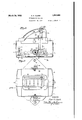
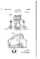
For a fuller understanding of my invention, reference may be had to the following description, taken in conjunction with the accompanying-drawings, in which Figure 1 is a View, in side elevation, of a thermostatic device embodyin my invention, Fig. 2 is a View in tront 'e evation of the same device, v
Fig. 3 is a view, in section, taken on the line III-III of Fig. 1,
Fig. 4. is a view, in section, taken on the line IVIV of Fig. 2,
Fig. 5 is a view, in section, taken on the line V-V of Fig.3,
Fig. 6 is a partial front plan view ofthe device shown in Figs. 1 to 4, inclusive embodied in the door of an oven, and
Fig-7 is a top plan view, partially in section, of the showing in Fig. 6. a
' In the drawings, a support 1,-of substantial- 4 1y channel shape, is provided with integral upturned lugs 2, 3 and 4 and openings 5 and 6 located at the ends thereof. The ends of the support are provided with lugs or tongues 7 and 8 that extend through end walls 9 and 10 of an open-end casing comprising two subotally supported on a pin 17 that extends through the portion of L-shape and the lugs 2 and 3. In order that a lever arm may be provided for turning the indicator 16 on its pivot pin 17 a pin 18 is provided that passes through the L-shaped portion of the indicator to the right of, and below, the pin 17, as viewed from Fig. 1. Y
The upperend of the indicator is provided with an offset portion of substantially U- shape that cooperates with a scale 19 of arouate shape that is secured to a scale support 21 which, in turn, is secured to, and supported by, the casing at 22 and 23 byrivets or other suitable means.
The indicator is provided with a cooperating control pointer 24 that is ivotally secured to the lug 4 by a rivet 25. 11 order that the pointer 24 may be frictionally held in a predetermined position, a spring lock'washer 26 is provided that is located between the lowerend of the pointer 24 and the lug. As in the case of the indicating pointer 16, the control pointer is provided with an offset portion 27 of substantially U-shape at its upper. end which cooperates with the scale 19.
In order that an electric circuit may be controlled by the indicating and control inters. 16 and 24, the pointers may be provi ed with contacts 28 and 29, respectively (see Figs. 3 and 5). The contacts are secured to the pointers by rivets or other suitable means and are insulated therefrom by washers 31 of insulating material.
In order that the point of contact between the contacts 28 and 29 may be protected from oxidation resulting from electric arcs their engaging ends may be provided with silvered rivets 32. The outer ends of the contacts 28 and 29 are provided witbflexible conductors 10b 33 and 34 that are electrically connected to terminals 35 and 36, respectively, the latter being secured to the casing portions 11 and 12. The terminals 35 and 36 may be insulated from the'casing by washers 37 of insulating material.
The terminals 35 and 36 being substantially similar, like parts will be designated by the same reference characters. These terminals comprise a substantially cylindrical connector 38 having a rivet portion 39, extending through the walls of the casing, and a strip 40 of substantially L-shape to which the flexible leads 33 and 34 may be connected either by brazing or other suitable methods.
The connectors 38 may be insulated from the casing by the mica washers 37, one of which fits into a depression in the casing and the other of which is locatedbetween the casing and the strip 40. As shown, the connectors 38 and the strips 40 are held securely together against the casing walls by the rivet portions 39.
In order that the indicating pointer 16 may be actuated in accordance with a thermal condition to be controlled, 2. bimetallic strip 41 is provided. One end of the strip 41 is secured to the free end of a cantilever spring 42 which, in turn, is secured to the support 1' by rivets or other suitable means. As shown in Fig. 1 of the drawings, the free end of the cantilever spring extends downwardly through the opening 5 in the support. 7
The free end of the bimetallic strip -41 is provided with a lug 44 having a recess 45 therein, in which the pin 18 of the pointer 16is located. If the bimetallic strip 41 is deflected, either in an upward or in a downward direction, as viewed from Fig. 1, the pin 18 slides in the recess 45, depending upon the direction of the deflection. As 'the strip is deflected, the pointer lflis caused to turn on its pivot pin 17. As is evident from Fig. 2 of the drawings, if the temperature of the strip 41 is increasing, the pointer 16 is caused to move up the scale 19, and if decreasing, the pointer moves in the opposite direction.
Since the point of contact between the lug 44 and the pin 18 changes as the strip 41 is deflected, the variation in the distance between the supported end of the strip and the point of contact between thepin 18 and the lug 44 is so compensated for that the indicating pointer 16 moves uniformly and substantially in direct proportion to the change in temperature of the strip.
Because the strip 41 is so secured to the spring 42 that the broad face or edge thereof is adjacent to the wall 15 of the oven door,
' themaximum-area of the strip issubjected to the temperature of the oven wall or lining 15, which, of course, is at a temperature propor- V tional to the temperature of the'interior' of the oven. As the maximum area. of the strip isutilized for absorbing heat conducted to it through which a handle 53 extends.
from the oven wall, the strip will be sensitive and will respond quickly to temperature changes within the oven.
It is to be notedthat, by supporting the bimetallic strip 41, as shown in the drawings,
the strip may be positioned closely to the gagement with a supporting member 48 that is secured to'the support 1. For convenience in manufacturing, the spring 42 may be disposed between the support 1 and the supporting member 48 so-that both the spring and the supporting member may be secured to the support 1 by the same rivets or securing means. I
By adjusting the supported end 0f the bimetallic strip-41, the pointer 16 .may be caused to indicate a temperature on the scale 19 that corresponds substantially to the actual temperature of the strip 41. Adjustment of the position of the pointer 16 obtained in this manner imposes no strains or initial stresses upon the strip, because only the position of the supported end of the bimetallic strip 41 is changed. The strip is not strained by'ad justing it, because it is evident that the stress I imposed is merely that of the weight of the pointer 16,which remains substantially constant over'its range of travel.
In order that the temperature at which conpointer 16 up the scale until the contacts 28 and 29 engage each other, thus causing an electric circuit (not shown) for energizing heating elements located in an electric oven (not shown) which are well-known to those skilled in the art, to be deenergized.
The indicating and control pointers and operating mechanism disposed in the casing may be protected fromexternal forces by a cover 49 that is secured to the top end of the casing by screws 50. The cover is provided with a window 51, in order that the scale 19 may be visible to the operator, and a slot 52 The handle is secured to the upper end of the moved to any redetermined position without the casing.
As shown in Fi 6 and 7 of the drawings,
the thermostatic evice illustrated in Figs. 1' to 4, inclusive, is inserted through an opening in an outer wall 56 of the oven 'door, the thermostat being secured to the inner wall 15, as previously set forth herein. When the thermostatic device is in place, an escutcheon plate 57 having an opening through which the cover 49 extends, is secured to the outer wall 56 of the door. 7
, The middle portion of the escutcheon plate and the outer wall of the oven door'so interfit with the upper end of the thermostat casing that the openings between the ends of the co'ver'and the endwalls of the casing are closed, thereby preventing'insulating material, located between the oven walls, from" getting into the thermostat (see Figs. 6 and 7 The escutcheonplate is provided with openings 58 and 59 at its bottom and top edges, throu h which air currents may circulate; there ore, the thermo-responsive bimetallic element 41 will not be located in a dead air space as a result of the chimney effect. produced by the escutcheon plate. The forwardly extending part of the casing is maintained at a relativel low temperature, thus making accidenta burning of an operator practically impossible.
Since the air circulates continually about the bimetallic element, the element will follow closely the temperature changes which take place within the oven. By properly pro-- portioning the dimensions of the imetallic element and properly adjusting the pivotal connections between its free end and the indicating pointer, the thermostatic device may be caused to follow substantially the er:- act temperature within the oven, that 15, 1f
the oven is being heated, the pointer 16 will indicate a temperature on the-scale 19 that is substantially equal to the exact temperature within the oven and, if the temperature is decreasing, the pointer will indicate on the scale substantial y the exact temperature of the oven as it cools. Therefore, it is seen that the chimney effect produced bg the openings in the escutcheon plate and t e open cas ing structure in which the bimetallic strip is located causesthe bimetallic member 41 to follow substantially the exact temperature within the oven.
Various modifications may be made in the devic embodying my invention without dearting from the spirit and the scope thereof. Idesire, therefore, that only such limitations shall be placed thereon as are imposed by the prior art and the appended claims. I claim as my invention:
1. In combination, a casing, a support therein adjacent to an open end thereof, an
. rang indicator pivotally mounted on the support, and a substantially strai ht flat bimetallic strip having one end yiel ingly and adjustabl mounted on said support and the other en pivotally connected'to said indicator, said strip havin its broad side located closely adjacent tot e open end of the casing.
2. In combination, an elongated support of substantially channel shape in lateral section, an indicator ivotally mounted thereon, anda substantial y straight vfiat bimetallic strip located within the channel -portion of the support and having one-end 'yieldingly mounted thereon and the other end having a pin-and-slot connection with said indicator, said strip having its broad side adjacent to the support. a
3. In a thermostatic device, in combination,
a casing having an open end adapted to be located closely adjacent to a heat-receiving member whose temperature is to be indicated, an elongated support extending along, and spaced from, said open end of the casing, an indicator of substantially L-shape and having legs of unequal length, pivotally mounted adjacent to one end of the elbngated support,
the longer leg extending away from the plane of the elongated support at substantially right angles thereto, a pin adacent to the end of the shorter leg, a
'bimetallic strip located between the support and the adjacent open end of the casing, a
resilient and adjustable mounting means for one end of the bimetallic strip and located near the other end of the support, and a slotted lug at the other end of the bimetallic strip for receiving the pin, whereby a sub stantially uniform movement of the end of the longer leg of the indicator is obtained for equal changes in temperature over a wide 4. In a thermostatic device adapted to be mounted in an opening in an outer wall of a double-wall oven structure, in combination, a casing having a portion adapted to extend in front of the front wall of the oven structure, an elongated support of channel shape in lateral section located adjacent to the rear end of the casing, a substantially straight flat bimetallic strip adjustably and resiliently secured to'the elongated sup ort near one end of the support, an indlcator pivotally mounted on the elongated support near the other end of the. support, a pin-and-slot connection between the indicator and the free end of the bimetallic strip, and an arcuate scale over which the movable end of the indicator may move, said scale bein located in that part of the casing adapte to extend in front of the front wall of the oven strucure.
5. A thermostatic device for a heated apbimetallic member having one end yieldingly mounted near the other end of said support and its other end having a pin and slot connection with said indicator, the support being arranged to present a broad face of the bimetal to anappliance with which the thermostatic device may be associated.
H 6. A thermostatic device including an elongated support having a plane surface, an indicator pivotally mounted near one end of the support, a substantially straight flat bimetallic member having one end yieldingly mounted near the other end of the support and its other end operatively engaging the indicator, and means-mounted on said support for adjusting the position of the yieldingly' mounted end of said bimetallic member in a direction at right angles toits flat surface.
7. A thermostatic device including an elongated support having a plane surface, an indicator pivotally mounted near one end of said support and extending laterally away from the plane surface, a leaf spring having one end secured near the other end-of the support and the other end unsupported, a substantially straight flat bimetallic member having one of its ends secured to the unsupported end of said spring, a pin" and slot connection between the other end of the bimetallic member. and the indicator, and means mounted near said other end of said support and engaging the unsupported end of the leaf spring for adjusting the position of that end of the spring and one end of the bimetallic member in a direction at right angles to its flat surface.
8. A thermostatic device including an elongated support having a plane surface, an indicating member pivotally mounted near one end of thesupport and extending laterally therefrom, said indicatingmember having a lever arm extending .from the. pivotal mounting in a direction longitudinally of the plane surface of the support, a pin extending through said lever arm, a substantially straight fiat bimetallic member having one of its ends supported near the other end of the support, and a lug secured to the other end of the bimetallic member, said lug having a slot therein extending in a direction longitudinally of the bimetallic member, through which said pin extends.
In testimony whereof I have hereuntosubscribed my name this 6th day of October,
" EARL K. CLARK.
Priority Applications (2)
| Application Number | Priority Date | Filing Date | Title |
|---|---|---|---|
| US227441A US1851564A (en) | 1927-10-20 | 1927-10-20 | Thermostatic device |
| US537793A US1873544A (en) | 1927-10-20 | 1931-05-16 | Thermostatic switch |
Applications Claiming Priority (1)
| Application Number | Priority Date | Filing Date | Title |
|---|---|---|---|
| US227441A US1851564A (en) | 1927-10-20 | 1927-10-20 | Thermostatic device |
Publications (1)
| Publication Number | Publication Date |
|---|---|
| US1851564A true US1851564A (en) | 1932-03-29 |
Family
ID=22853122
Family Applications (1)
| Application Number | Title | Priority Date | Filing Date |
|---|---|---|---|
| US227441A Expired - Lifetime US1851564A (en) | 1927-10-20 | 1927-10-20 | Thermostatic device |
Country Status (1)
| Country | Link |
|---|---|
| US (1) | US1851564A (en) |
-
1927
- 1927-10-20 US US227441A patent/US1851564A/en not_active Expired - Lifetime
Similar Documents
| Publication | Publication Date | Title |
|---|---|---|
| US2564321A (en) | Timing device | |
| US1612114A (en) | Thermal responsive circuit controller | |
| US2622171A (en) | Bimetal strip thermostat | |
| US2439795A (en) | Thermostat | |
| US2184270A (en) | Heating device | |
| US1851564A (en) | Thermostatic device | |
| US1930062A (en) | Temperature indicating thermostat | |
| US2500760A (en) | Thermostatic switch | |
| USRE21038E (en) | Magnetic switch | |
| US2943177A (en) | Thermostatic switch | |
| US2201115A (en) | Automatic flatiron, and thermostatic device for controlling the same | |
| US1881950A (en) | Thermostatically controlled switch | |
| US2616358A (en) | Toaster | |
| US1724425A (en) | Thermostat | |
| US1873544A (en) | Thermostatic switch | |
| US2878344A (en) | Thermal responsive switching device | |
| US2472638A (en) | Thermostatic control device | |
| US2667115A (en) | Toaster | |
| US2928918A (en) | Snap action switch | |
| US1673591A (en) | Temperature indicator and controller | |
| US2044397A (en) | Temperature responsive switch | |
| US2464944A (en) | Condition responsive device | |
| US1969105A (en) | Thermoresponsive electric controller | |
| US1937058A (en) | Thermostat for electric heaters | |
| US2587334A (en) | Control device |