US1851561A - Bearing mounting - Google Patents
Bearing mounting Download PDFInfo
- Publication number
- US1851561A US1851561A US196582A US19658227A US1851561A US 1851561 A US1851561 A US 1851561A US 196582 A US196582 A US 196582A US 19658227 A US19658227 A US 19658227A US 1851561 A US1851561 A US 1851561A
- Authority
- US
- United States
- Prior art keywords
- sleeve
- shaft
- casing
- bearings
- rib
- Prior art date
- Legal status (The legal status is an assumption and is not a legal conclusion. Google has not performed a legal analysis and makes no representation as to the accuracy of the status listed.)
- Expired - Lifetime
Links
- 239000000463 material Substances 0.000 description 14
- 230000035939 shock Effects 0.000 description 13
- 238000010276 construction Methods 0.000 description 5
- 230000006835 compression Effects 0.000 description 2
- 238000007906 compression Methods 0.000 description 2
- 230000003247 decreasing effect Effects 0.000 description 2
- 239000000314 lubricant Substances 0.000 description 2
- 238000005096 rolling process Methods 0.000 description 2
- 230000002159 abnormal effect Effects 0.000 description 1
- 230000001066 destructive effect Effects 0.000 description 1
- 238000004519 manufacturing process Methods 0.000 description 1
- 238000000926 separation method Methods 0.000 description 1
- 230000002459 sustained effect Effects 0.000 description 1
Images
Classifications
-
- B—PERFORMING OPERATIONS; TRANSPORTING
- B60—VEHICLES IN GENERAL
- B60B—VEHICLE WHEELS; CASTORS; AXLES FOR WHEELS OR CASTORS; INCREASING WHEEL ADHESION
- B60B37/00—Wheel-axle combinations, e.g. wheel sets
- B60B37/10—Wheel-axle combinations, e.g. wheel sets the wheels being individually rotatable around the axles
-
- F—MECHANICAL ENGINEERING; LIGHTING; HEATING; WEAPONS; BLASTING
- F16—ENGINEERING ELEMENTS AND UNITS; GENERAL MEASURES FOR PRODUCING AND MAINTAINING EFFECTIVE FUNCTIONING OF MACHINES OR INSTALLATIONS; THERMAL INSULATION IN GENERAL
- F16C—SHAFTS; FLEXIBLE SHAFTS; ELEMENTS OR CRANKSHAFT MECHANISMS; ROTARY BODIES OTHER THAN GEARING ELEMENTS; BEARINGS
- F16C19/00—Bearings with rolling contact, for exclusively rotary movement
- F16C19/54—Systems consisting of a plurality of bearings with rolling friction
- F16C19/546—Systems with spaced apart rolling bearings including at least one angular contact bearing
- F16C19/547—Systems with spaced apart rolling bearings including at least one angular contact bearing with two angular contact rolling bearings
- F16C19/548—Systems with spaced apart rolling bearings including at least one angular contact bearing with two angular contact rolling bearings in O-arrangement
-
- F—MECHANICAL ENGINEERING; LIGHTING; HEATING; WEAPONS; BLASTING
- F16—ENGINEERING ELEMENTS AND UNITS; GENERAL MEASURES FOR PRODUCING AND MAINTAINING EFFECTIVE FUNCTIONING OF MACHINES OR INSTALLATIONS; THERMAL INSULATION IN GENERAL
- F16C—SHAFTS; FLEXIBLE SHAFTS; ELEMENTS OR CRANKSHAFT MECHANISMS; ROTARY BODIES OTHER THAN GEARING ELEMENTS; BEARINGS
- F16C25/00—Bearings for exclusively rotary movement adjustable for wear or play
- F16C25/06—Ball or roller bearings
- F16C25/08—Ball or roller bearings self-adjusting
- F16C25/083—Ball or roller bearings self-adjusting with resilient means acting axially on a race ring to preload the bearing
-
- F—MECHANICAL ENGINEERING; LIGHTING; HEATING; WEAPONS; BLASTING
- F16—ENGINEERING ELEMENTS AND UNITS; GENERAL MEASURES FOR PRODUCING AND MAINTAINING EFFECTIVE FUNCTIONING OF MACHINES OR INSTALLATIONS; THERMAL INSULATION IN GENERAL
- F16C—SHAFTS; FLEXIBLE SHAFTS; ELEMENTS OR CRANKSHAFT MECHANISMS; ROTARY BODIES OTHER THAN GEARING ELEMENTS; BEARINGS
- F16C27/00—Elastic or yielding bearings or bearing supports, for exclusively rotary movement
- F16C27/06—Elastic or yielding bearings or bearing supports, for exclusively rotary movement by means of parts of rubber or like materials
- F16C27/066—Ball or roller bearings
-
- F—MECHANICAL ENGINEERING; LIGHTING; HEATING; WEAPONS; BLASTING
- F16—ENGINEERING ELEMENTS AND UNITS; GENERAL MEASURES FOR PRODUCING AND MAINTAINING EFFECTIVE FUNCTIONING OF MACHINES OR INSTALLATIONS; THERMAL INSULATION IN GENERAL
- F16C—SHAFTS; FLEXIBLE SHAFTS; ELEMENTS OR CRANKSHAFT MECHANISMS; ROTARY BODIES OTHER THAN GEARING ELEMENTS; BEARINGS
- F16C19/00—Bearings with rolling contact, for exclusively rotary movement
- F16C19/02—Bearings with rolling contact, for exclusively rotary movement with bearing balls essentially of the same size in one or more circular rows
- F16C19/14—Bearings with rolling contact, for exclusively rotary movement with bearing balls essentially of the same size in one or more circular rows for both radial and axial load
- F16C19/16—Bearings with rolling contact, for exclusively rotary movement with bearing balls essentially of the same size in one or more circular rows for both radial and axial load with a single row of balls
- F16C19/163—Bearings with rolling contact, for exclusively rotary movement with bearing balls essentially of the same size in one or more circular rows for both radial and axial load with a single row of balls with angular contact
-
- F—MECHANICAL ENGINEERING; LIGHTING; HEATING; WEAPONS; BLASTING
- F16—ENGINEERING ELEMENTS AND UNITS; GENERAL MEASURES FOR PRODUCING AND MAINTAINING EFFECTIVE FUNCTIONING OF MACHINES OR INSTALLATIONS; THERMAL INSULATION IN GENERAL
- F16C—SHAFTS; FLEXIBLE SHAFTS; ELEMENTS OR CRANKSHAFT MECHANISMS; ROTARY BODIES OTHER THAN GEARING ELEMENTS; BEARINGS
- F16C2326/00—Articles relating to transporting
- F16C2326/01—Parts of vehicles in general
- F16C2326/02—Wheel hubs or castors
-
- F—MECHANICAL ENGINEERING; LIGHTING; HEATING; WEAPONS; BLASTING
- F16—ENGINEERING ELEMENTS AND UNITS; GENERAL MEASURES FOR PRODUCING AND MAINTAINING EFFECTIVE FUNCTIONING OF MACHINES OR INSTALLATIONS; THERMAL INSULATION IN GENERAL
- F16C—SHAFTS; FLEXIBLE SHAFTS; ELEMENTS OR CRANKSHAFT MECHANISMS; ROTARY BODIES OTHER THAN GEARING ELEMENTS; BEARINGS
- F16C2326/00—Articles relating to transporting
- F16C2326/10—Railway vehicles
Definitions
- This invention relates to hearing mount-' ings and comprises all the features of novelty herein disclosed, by way of example, in connection with load cushioned bearing mountings for wheels or shafts to cushion rolling bearings against the shock of end thrusts and heavy radial loads.
- the numeral 2 indicates the rim of a wheel such as the flanged rim of a carwheel having a hub or casing 4 provided with a cylindrical bore 6 and with a cylindrical counterbore 8 terminating in an annularshoulder 10 which forms an abutment and one end wall of a recess.
- the bore 6 has a free slip fit on the cylindrical periphery of a rotatable sleeve 12 having a central projection in the form of an outwardly extending annular rib 14.
- Compressible cushioning material such as rubber in the form of rings 16 is inserted between the rib 14 and the shoulder 10, and between the rib and a second abutment formed bv the end of a flanged ring 18 which also has a cylindrical bore 19 with a free slip fit on the sleeve 12.
- the clearance between the sleeve 12 and the enclosing bores 6 and 19 is small (being exaggerated in the figure) and under certain conditions the surfaces can come into contact aswill appear.
- Thering 18 is a detachable part of the hub or casin 4 and has'an end flange 20 secured to the hu or casing by screw bolts 22.
- the ring 18 and shoulder 10 radially overlap the rib 14 and define the ends of an annular recess in the casing and provide annular faces opposed to and axially spaced from annular faces at the sides of rib 14. Suitable shims or washers.
- the flange 20 may be inserted between the flange 20 and the casing to adjust the position of the ring 18, for the purpose of applying the desired initial pressure to the compressible cushioning material to cause the latter to sustainan desired amount ofradial load before thes eeve .and casing come into actual contact.
- the end of the sleeve is preferably provided with teeth 25 to interlock with similar teeth on a dished cap 26 bolted to the casing.
- any suitable plain or rolling bearings may be provided for rotatably supporting the sleeve 12.
- the sleeve has an inwardly extending annular extension 28 forming shoulders to abut against outer race rings 30 of ball bearings 32 and 34 of the angular contact type which have the r thrust shoulders facing away from each other.
- Inner race rings 36 having their thrust shoulders facing one another, are sleeved on an axle or shaft 38, the inner race ring of bearing 32 being held by a nut '40 screwed on the end of the shaft or axle.
- the other inner race ring abuts against a ring 42 which has a flange 44 bearing against a shoulder on the shaft.
- the bearings hold the sleeve 12 aga nst endwise movement with respect to the shaft but, whenever one of the cushions is compressed by an axial shock load, relative axial movement between the shaft and the casing is permitted by the lost motion space between the ends of the interlocking teeth 25 and the bottom of their cooperating notches.
- a lubricant holding washer 46 fitting n the sleeve 12 is enclosed by a flanged nut 48 threaded in the sleeve 12 and having a flange 5O closely embracing the ring 42 at the side of the flange 44.
- Slight initial compression of the cushioning material may be suflicient to hold the hub or casing to the sleeve 12 to turn with the latter but the cushioning material can be compressed to any desired extent by varying the shims or washers 24 in order that the desired amount of radial load will be sustained before the casing and sleeve come into actual supporting contact.
- the flanged ring 18 is the only member which needs to be removed and the bearings are left undisturbed and en-
- the benefits of the invention may also be obtained in a structure wherein the axle or shaft is rotatable and the hub or similar member 4 is a relatively fixed casing.
- a casing or journal box 54 a rotary shaft or axle 56, the shaft mounted on bearings 58 and being rotatably I which is provided with cush- 60in a sleeve 62 ioning material
- the details of construction may be analogous to the construction illustrated and described in connection with Figure 1.
- casing or journal box 64 receives a rotary shaft or axle 66, the shaft carrying inner race by a sleeve 72 and held by a nut 74 threaded on the end of the shaft.
- Ball bearings 76 and 78 have their outer race rings 80 and 82 abutting against shoulders in a sleeve composed of two sections 84 and 86 which have interlocking teeth 88 to prevent relative rotation. There is a small axial clearance between the sleeve sections to allow a relative axial movement.
- One of the sleeve rings 68 and spaced sections has teeth 90 interlocking with similar teeth on a cap 92 secured to the casing 64 and the sleeve section and cap have provision for a little relative axial movement as by the axial space between the ends of the teeth 90 and the bottom of the cooperating notches.
- the box is conveniently split, as on the horizontal center line, to provide for assembly.
- An annular projection or rib in the form' of a ring 94 is inserted in a groove in the interior of the box-and projects inwardly into an annular recess formed between shoulders 96 and 98 near the adjacent ends of the sleeve secportions.
- the sleeve sections have external sliding engagement with the cylindrical inner surface between it and the journal cess between its ends,
- the casing compressing the spring washers 102 which absorb the shock and relieve the bearings 78.
- the opposing spring washers 100 being under their initial tension, cause the other sleeve section 84 to slide in the box and maintain the initial thrust load on the bearing 76.
- the sleeve sections slide in the same direction simultaneously. End thrust load or shock in the other direction is absorbed by the spring washers100 in a similar manner.
- the end of the sleeve section 86 may be provided with a ring nut 104 andv a suitable lubricant seal as in the other embodiments of the invention.
- the shaft a sleeve surrounding the shaft, a casing surrounding the sleeve, spaced bearings of angular contact type interposed between the sleeve and the shaft to prevent relative axial movement between the sleeve and the shaft while providing for relative rotation between them, the sleeve having an outwardly projecting rib and the casing having an internal projection overlapping the rib, the rib and projection being axially spaced to I approach or recede from one another in an axial direction, compressible cushioning material interposed axially between the rib and the projection for yieldingly resisting said axial movement and relieving the bearings of axial shock loads, and lost motion interengaging means allowing the sleeve and the casing to have said relative axial movement while preventing relative rotation thereof; substantially as described.
- a shaft a sleeve surrounding the shaft, a casing surrounding the sleeve, thrust and radial load bearing means interposed between the sleeve and one of the other members to prevent relative axial movement between the sleeve and said one other member while providing for relative rotation between them, the sleeve having a projection and the remaining member having a recess receiving the projection between the end walls thereof, cushioning material in the recess at each side of the projection, and a removable plate attached to said remaining member and forming one of said end walls; substantially as described.
Landscapes
- Engineering & Computer Science (AREA)
- General Engineering & Computer Science (AREA)
- Mechanical Engineering (AREA)
- Support Of The Bearing (AREA)
Description
March 29, 1932. J BANlNGER 1,851,561
BEARING MOUNTING Filed June 4. 1927 Fig.2.
/oo /o2 96 94 98 v lNvENTOB; Fig. 3. JOHN H. BANINGEQ,
H/s A TTo/QP/E? 2 improved wheel Patented Mar. 29, 1932' PATENT OFFICE JOHN H. BANINGER, OF
BRISTOL, CONNECTICUT, .ASSTGNOB TO THE NEW DEPARTURE MANUFACTURING COMPANY, OF BRISTOL, CONNECTICUT, A CORPORATION OF CONNECTICUT BEARING MOUNTING Application man an. 4, 1927. Serial No. 196,582.
This invention relates to hearing mount-' ings and comprises all the features of novelty herein disclosed, by way of example, in connection with load cushioned bearing mountings for wheels or shafts to cushion rolling bearings against the shock of end thrusts and heavy radial loads.
An object of the invention is to provide an or shaft mounting in which antifriction or other bearings can be used to advantage without excessive or destructive shock loads coming upon them, therebv enabling smaller bearings to be used without sacrifice of service or accuracy. Another object is to provide an improved wheel or shaft mounting wherein radial load shocks and end thrust shocks, or either radial or end thrust shocks will be damped and noise decreased. To these ends and to improve generally upon devices of this character, the invention also consists in the various matters hereinafter described and claimed.
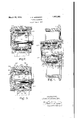
In its broader aspects, the invention is not necessarily limited to the specific constructions selected for illustrative purposes in the accompanying drawings in which Figure 1 is an axial section through one form of cushioned bearing mounting and Figures 2 and 3 are similar views of modified forms of mountings.
The numeral 2 indicates the rim of a wheel such as the flanged rim of a carwheel having a hub or casing 4 provided with a cylindrical bore 6 and with a cylindrical counterbore 8 terminating in an annularshoulder 10 which forms an abutment and one end wall of a recess. The bore 6 has a free slip fit on the cylindrical periphery of a rotatable sleeve 12 having a central projection in the form of an outwardly extending annular rib 14. Compressible cushioning material, such as rubber in the form of rings 16, is inserted between the rib 14 and the shoulder 10, and between the rib and a second abutment formed bv the end of a flanged ring 18 which also has a cylindrical bore 19 with a free slip fit on the sleeve 12.. The clearance between the sleeve 12 and the enclosing bores 6 and 19 is small (being exaggerated in the figure) and under certain conditions the surfaces can come into contact aswill appear. Thering 18 is a detachable part of the hub or casin 4 and has'an end flange 20 secured to the hu or casing by screw bolts 22. The ring 18 and shoulder 10 radially overlap the rib 14 and define the ends of an annular recess in the casing and provide annular faces opposed to and axially spaced from annular faces at the sides of rib 14. Suitable shims or washers.
24 may be inserted between the flange 20 and the casing to adjust the position of the ring 18, for the purpose of applying the desired initial pressure to the compressible cushioning material to cause the latter to sustainan desired amount ofradial load before thes eeve .and casing come into actual contact. The
compression of the material tends to cause the casing and sleeve to rotate as one but, to prevent possibility of relativev rotation, the end of the sleeve is preferably provided with teeth 25 to interlock with similar teeth on a dished cap 26 bolted to the casing.
Any suitable plain or rolling bearings may be provided for rotatably supporting the sleeve 12. In the illustrated construction, the sleeve has an inwardly extending annular extension 28 forming shoulders to abut against outer race rings 30 of ball bearings 32 and 34 of the angular contact type which have the r thrust shoulders facing away from each other. Inner race rings 36, having their thrust shoulders facing one another, are sleeved on an axle or shaft 38, the inner race ring of bearing 32 being held by a nut '40 screwed on the end of the shaft or axle. The other inner race ring abuts against a ring 42 which has a flange 44 bearing against a shoulder on the shaft. The bearings hold the sleeve 12 aga nst endwise movement with respect to the shaft but, whenever one of the cushions is compressed by an axial shock load, relative axial movement between the shaft and the casing is permitted by the lost motion space between the ends of the interlocking teeth 25 and the bottom of their cooperating notches. A lubricant holding washer 46 fitting n the sleeve 12 is enclosed by a flanged nut 48 threaded in the sleeve 12 and having a flange 5O closely embracing the ring 42 at the side of the flange 44.
tions outside their interlocking shaft or axle are absorbed closed by the sleeve 12.
receives box.
Lateral thrust forces causing relative axial movement between the hub or casing and the or damped by the cushioning material thereby lessening noise and decreasing shock load on the antifriction bearings. Normal radial load is also transmitted through the cushioning material which d'amps radial shock such as that caused by the wheel travelling over rail joints. In case of abnormal load, the sleeve 12 can come into actual load contact with the bores 6 and 19 of the hub or casing. Slight initial compression of the cushioning material may be suflicient to hold the hub or casing to the sleeve 12 to turn with the latter but the cushioning material can be compressed to any desired extent by varying the shims or washers 24 in order that the desired amount of radial load will be sustained before the casing and sleeve come into actual supporting contact. To remove the wheel, the flanged ring 18 is the only member which needs to be removed and the bearings are left undisturbed and en- The benefits of the invention may also be obtained in a structure wherein the axle or shaft is rotatable and the hub or similar member 4 is a relatively fixed casing.
In Figure 2, a casing or journal box 54 a rotary shaft or axle 56, the shaft mounted on bearings 58 and being rotatably I which is provided with cush- 60in a sleeve 62 ioning material The details of construction may be analogous to the construction illustrated and described in connection with Figure 1.
In Figure 3, the construction is such as to cushion end thrust shockon the bearings. A
casing or journal box 64 receives a rotary shaft or axle 66, the shaft carrying inner race by a sleeve 72 and held by a nut 74 threaded on the end of the shaft. Ball bearings 76 and 78 have their outer race rings 80 and 82 abutting against shoulders in a sleeve composed of two sections 84 and 86 which have interlocking teeth 88 to prevent relative rotation. There is a small axial clearance between the sleeve sections to allow a relative axial movement. One of the sleeve rings 68 and spaced sections has teeth 90 interlocking with similar teeth on a cap 92 secured to the casing 64 and the sleeve section and cap have provision for a little relative axial movement as by the axial space between the ends of the teeth 90 and the bottom of the cooperating notches. The box is conveniently split, as on the horizontal center line, to provide for assembly. An annular projection or rib in the form' of a ring 94 is inserted in a groove in the interior of the box-and projects inwardly into an annular recess formed between shoulders 96 and 98 near the adjacent ends of the sleeve secportions.
The sleeve sections have external sliding engagement with the cylindrical inner surface between it and the journal cess between its ends,
means in the form of series of' 1n the casing compressing the spring washers 102 which absorb the shock and relieve the bearings 78. The opposing spring washers 100, being under their initial tension, cause the other sleeve section 84 to slide in the box and maintain the initial thrust load on the bearing 76. Thus the sleeve sections slide in the same direction simultaneously. End thrust load or shock in the other direction is absorbed by the spring washers100 in a similar manner. The end of the sleeve section 86 may be provided with a ring nut 104 andv a suitable lubricant seal as in the other embodiments of the invention.
I claim:
1. The combination with a shaft and a casing between which there is-relative rotation, one of said members having anabutment, of bearings mounted upon the other of said members, a sleeve between said bearings and said member having said abutment, said sleeve also being mounted upon said bearings, an-abutment upon said sleeve axially spaced from said first-recited abutment but radially over-lapping the same, one abutment being movable axially towards the other, and a resilient cushion between said abutments tocushion said axial movement; substantially as described.
2. The combination with a shaft and a casing between which there is relative rotation, one of said members being provided with a recess, of thrust and. radial load bearings mounted upon the other of said members, a sleeve between said bearings and said recessed member and also mounted uponsaid bearings, a projection upon said sleeve and extending into said recess, the projection radially overlapping but axially spaced from the end walls of the recess to approach one of them, and a resilient cushion in said recess at each side of said projection to relieve the ings and said recessed member and also mounted upon said bearings, an annular rib upon said sleeve and pro ect1ng into said reand a resilient cushioning ring in said recess at each side of said rib; substantially as described.
4. The combination with a shaft and a casing between which there is relative rotation, one of said members having a projection extending toward the other thereof, pf bearings mounted upon such other of sa d members, a plate removably secured to said member having said projection and co-operating with said projection to produce a recess, a
- casing and having the cups of said bearings secured thereto, a projection upon said sleeve extending into said recess of said casing, and a resilient cushion in said recess at each side of said sleeve-projection; substantially as described.
6'. In a device of the character described,
a shaft, a sleeve surrounding the'shaft, a casving surrounding the sleeve, thrust and radial load bearing means interposed between the sleeve and one of the other members to prevent relative axial movement between the sleeve and said one other member while providing for relative rotation between them, that surface of the sleeve which is opposite to the bearing means, and the remaining member, having axially spaced and radially overlapping parts which can approach and recede from one another in an axial direction, and compressible cushioning material interposed axially between said overlapping parts for yieldingly resisting said axial movement and relieving the bearing means of axial shock load: substantially as described.
7 In a device of the character described, a shaft, a sleeve surrounding the shaft, a casing surrounding the sleeve, spaced bearings of angular contact type interposed between the sleeve and one of the other members to prevent relative axial movement between the sleeve and said one other member while providing for relative rotation between them, that surface of the sleeve which is opposite to the bearings, and the remaining member, having axially spaced and radially overlapping parts which can approach and recede from one another in an axial direction, said overlapping parts comprising an annular rib extending between spaced annular surfaces, compressible cushioning material interposed axially between opposite sides of the rib and the annular surfaces for yieldingly resisting said axial movement and thereby relieving the bearings of axial shock loads in two directions; substantially as described.
8. In a device of the character described, a
shaft, a sleeve surrounding the shaft, a casing surrounding the sleeve, spaced bearings of angular contact type interposed between the sleeve and the shaft to prevent relative axial movement between the sleeve and the shaft while providing for relative rotation between them, the sleeve having an outwardly projecting rib and the casing having an internal projection overlapping the rib, the rib and projection being axially spaced to I approach or recede from one another in an axial direction, compressible cushioning material interposed axially between the rib and the projection for yieldingly resisting said axial movement and relieving the bearings of axial shock loads, and lost motion interengaging means allowing the sleeve and the casing to have said relative axial movement while preventing relative rotation thereof; substantially as described.
9. In a device of the character described, a shaft, a sleeve surrounding the shaft, a casing surrounding the sleeve, thrust and radial load bearing means interposed between the sleeve and one of the other members to prevent relative axial movement between the sleeve and said one other member while providing for relative rotation between them, the sleeve and the remaining member having axially spaced and radially overlapping parts which can approach and recede from one another in an axial direction, compressible cushioning material interposed axially between said overlapping parts, and one of said overlapping parts comprising a plate removably attached to its supporting member to provide for separation of shaft and casingwithout disturbing the bearing means; substantially as described.
10. In a device of the character described, a shaft, a sleeve surrounding the shaft, a casing surrounding the sleeve, thrust and radial load bearing means interposed between the sleeve and one of the other members to prevent relative axial movement between the sleeve and said one other member while providing for relative rotation between them, the sleeve having a projection and the remaining member having a recess receiving the projection between the end walls thereof, cushioning material in the recess at each side of the projection, and a removable plate attached to said remaining member and forming one of said end walls; substantially as described.
11. In a device of the character described, a shaft, a sleeve surrounding the shaft, a casing surrounding the sleeve, thrust and radial load bearing means interposed between the sleeve and one of the other members to prevent relative axial movement between the sleeve and said one other member while providing for relative rotation'between them, the sleeve having an annular rib and the remaining member having a recess receiving the rib axially between the end walls thereof, rings of cushioning material in the recess and enga 'ng opposite sides of the rib, and a removal 1e ring attached to said remaining member and forming one of the end walls of the recess; substantially as described.
In testimony whereof I hereunto afiix my signature.
' JOHN H. BANIN GER.
Priority Applications (1)
| Application Number | Priority Date | Filing Date | Title |
|---|---|---|---|
| US196582A US1851561A (en) | 1927-06-04 | 1927-06-04 | Bearing mounting |
Applications Claiming Priority (1)
| Application Number | Priority Date | Filing Date | Title |
|---|---|---|---|
| US196582A US1851561A (en) | 1927-06-04 | 1927-06-04 | Bearing mounting |
Publications (1)
| Publication Number | Publication Date |
|---|---|
| US1851561A true US1851561A (en) | 1932-03-29 |
Family
ID=22725965
Family Applications (1)
| Application Number | Title | Priority Date | Filing Date |
|---|---|---|---|
| US196582A Expired - Lifetime US1851561A (en) | 1927-06-04 | 1927-06-04 | Bearing mounting |
Country Status (1)
| Country | Link |
|---|---|
| US (1) | US1851561A (en) |
Cited By (22)
| Publication number | Priority date | Publication date | Assignee | Title |
|---|---|---|---|---|
| US2481812A (en) * | 1948-10-07 | 1949-09-13 | Crompton & Knowles Loom Works | Picking mechanism for looms |
| US2563778A (en) * | 1949-01-24 | 1951-08-07 | Sandy Hill Iron & Brass Corp | Bearing |
| US2572411A (en) * | 1947-11-17 | 1951-10-23 | Watt Thomas | Resilient support for antifriction bearings |
| US2628871A (en) * | 1949-04-01 | 1953-02-17 | Gen Electric | Tandem bearing assembly and lubrication thereof |
| US2670242A (en) * | 1948-06-30 | 1954-02-23 | Chicago Roller Skate Co | Roller structure |
| US2674505A (en) * | 1951-07-07 | 1954-04-06 | Connecticut Hard Rubber Co | Rubber mounted bearing |
| US2689769A (en) * | 1949-03-05 | 1954-09-21 | Chicago Roller Skate Co | Skate roller structure |
| US2733108A (en) * | 1956-01-31 | Cushioned hinge bearing | ||
| DE965774C (en) * | 1951-12-05 | 1957-06-19 | Licentia Gmbh | Compensating device for several roller bearings, in particular ball bearings without radial springs, mounted shafts, preferably electrical machines, to eliminate internal clearance and axial play and to dampen mechanical vibrations |
| US2886353A (en) * | 1956-06-01 | 1959-05-12 | John A Mcinerney | Shaft seal |
| US3053591A (en) * | 1957-08-16 | 1962-09-11 | Schaeffler Ohg Industriewerk | Adjustable clearance antifriction bearing |
| DE1207998B (en) * | 1964-09-04 | 1965-12-30 | Licentia Gmbh | Method for assembling small electrical machines with a runner shaft mounted on one side on a bearing plate and a stator core attached |
| US3241892A (en) * | 1962-06-11 | 1966-03-22 | Trico Products Corp | Windshield wiper linkage |
| US3942314A (en) * | 1974-11-27 | 1976-03-09 | Lord Corporation | Textile spindle mounting |
| DE4017572A1 (en) * | 1990-05-31 | 1991-12-05 | Baumueller Nuernberg Gmbh | ELECTRICAL MACHINE WITH FIXED LOS BEARING |
| EP0806831A1 (en) * | 1996-05-06 | 1997-11-12 | Carrier Corporation | Spring deflexion limiting device |
| US6631961B1 (en) * | 2001-08-27 | 2003-10-14 | Caterpillar Inc | Isolated rim idler |
| US20050058378A1 (en) * | 2003-09-15 | 2005-03-17 | Goss James D. | Bearing cup rotational lock assembly |
| US20050146100A1 (en) * | 2000-02-28 | 2005-07-07 | Hurwitz Myron S. | Generation of in-line skates and skate-boards with safety "EDGING FRICTION CONTROL™" |
| US20080210028A1 (en) * | 2007-03-02 | 2008-09-04 | Disco Corporation | Driving mechanism and cutting apparatus having the driving mechanism |
| DE102008025490A1 (en) * | 2008-05-28 | 2009-12-10 | WINKLER + DüNNEBIER AG | Storage for a vacuum roll to be acted upon with suction on both sides |
| US9222517B1 (en) * | 2014-11-26 | 2015-12-29 | Bradford Christopher King | Tapered bearing system to minimize shaft damage and component failure |
-
1927
- 1927-06-04 US US196582A patent/US1851561A/en not_active Expired - Lifetime
Cited By (27)
| Publication number | Priority date | Publication date | Assignee | Title |
|---|---|---|---|---|
| US2733108A (en) * | 1956-01-31 | Cushioned hinge bearing | ||
| US2572411A (en) * | 1947-11-17 | 1951-10-23 | Watt Thomas | Resilient support for antifriction bearings |
| US2670242A (en) * | 1948-06-30 | 1954-02-23 | Chicago Roller Skate Co | Roller structure |
| US2481812A (en) * | 1948-10-07 | 1949-09-13 | Crompton & Knowles Loom Works | Picking mechanism for looms |
| US2563778A (en) * | 1949-01-24 | 1951-08-07 | Sandy Hill Iron & Brass Corp | Bearing |
| US2689769A (en) * | 1949-03-05 | 1954-09-21 | Chicago Roller Skate Co | Skate roller structure |
| US2628871A (en) * | 1949-04-01 | 1953-02-17 | Gen Electric | Tandem bearing assembly and lubrication thereof |
| US2674505A (en) * | 1951-07-07 | 1954-04-06 | Connecticut Hard Rubber Co | Rubber mounted bearing |
| DE965774C (en) * | 1951-12-05 | 1957-06-19 | Licentia Gmbh | Compensating device for several roller bearings, in particular ball bearings without radial springs, mounted shafts, preferably electrical machines, to eliminate internal clearance and axial play and to dampen mechanical vibrations |
| US2886353A (en) * | 1956-06-01 | 1959-05-12 | John A Mcinerney | Shaft seal |
| US3053591A (en) * | 1957-08-16 | 1962-09-11 | Schaeffler Ohg Industriewerk | Adjustable clearance antifriction bearing |
| US3241892A (en) * | 1962-06-11 | 1966-03-22 | Trico Products Corp | Windshield wiper linkage |
| DE1207998B (en) * | 1964-09-04 | 1965-12-30 | Licentia Gmbh | Method for assembling small electrical machines with a runner shaft mounted on one side on a bearing plate and a stator core attached |
| US3942314A (en) * | 1974-11-27 | 1976-03-09 | Lord Corporation | Textile spindle mounting |
| DE4017572A1 (en) * | 1990-05-31 | 1991-12-05 | Baumueller Nuernberg Gmbh | ELECTRICAL MACHINE WITH FIXED LOS BEARING |
| EP0806831A1 (en) * | 1996-05-06 | 1997-11-12 | Carrier Corporation | Spring deflexion limiting device |
| US5719454A (en) * | 1996-05-06 | 1998-02-17 | Carrier Corporation | Spring life improvement |
| US7108331B2 (en) * | 2000-02-28 | 2006-09-19 | Myron Stuart Hurwitz | Generation of in-line skates and skate-boards with safety “EDGING FRICTION CONTROL™” |
| US20050146100A1 (en) * | 2000-02-28 | 2005-07-07 | Hurwitz Myron S. | Generation of in-line skates and skate-boards with safety "EDGING FRICTION CONTROL™" |
| US6631961B1 (en) * | 2001-08-27 | 2003-10-14 | Caterpillar Inc | Isolated rim idler |
| US20050058378A1 (en) * | 2003-09-15 | 2005-03-17 | Goss James D. | Bearing cup rotational lock assembly |
| US7594760B2 (en) * | 2003-09-15 | 2009-09-29 | Pratt & Whitney Rocketdyne, Inc. | Bearing cup rotational lock assembly |
| US20080210028A1 (en) * | 2007-03-02 | 2008-09-04 | Disco Corporation | Driving mechanism and cutting apparatus having the driving mechanism |
| DE102008025490A1 (en) * | 2008-05-28 | 2009-12-10 | WINKLER + DüNNEBIER AG | Storage for a vacuum roll to be acted upon with suction on both sides |
| US20110069921A1 (en) * | 2008-05-28 | 2011-03-24 | Winkler + Dunnebier Ag | Bearing for a vacuum roller that can be subjected to suction air from both sides |
| DE102008025490B4 (en) * | 2008-05-28 | 2017-01-05 | Winkler + Dünnebier Gmbh | Storage for a vacuum roll to be acted upon with suction on both sides |
| US9222517B1 (en) * | 2014-11-26 | 2015-12-29 | Bradford Christopher King | Tapered bearing system to minimize shaft damage and component failure |
Similar Documents
| Publication | Publication Date | Title |
|---|---|---|
| US1851561A (en) | Bearing mounting | |
| US3135224A (en) | Traction motor suspension | |
| US1787459A (en) | Journal-box closure | |
| US1638957A (en) | Journal bearing | |
| US378978A (en) | Matthew byan | |
| US1094312A (en) | Ball-bearing. | |
| US1774655A (en) | Car-journal roller-bearing box | |
| US830100A (en) | Antifriction-bearing. | |
| US1206505A (en) | Roller-bearing. | |
| US2744474A (en) | Railway bearing | |
| US1877206A (en) | Shaft bearing | |
| US2703738A (en) | Cylindrical roller bearings | |
| US1648413A (en) | Railway-car-wheel construction | |
| US1186252A (en) | Combined roller and ball bearing. | |
| US2155657A (en) | Thrust bearing | |
| US958586A (en) | Roller-bearing. | |
| US408288A (en) | Anti-friction journal-box | |
| US1719941A (en) | Vehicle wheel bearing | |
| US1843292A (en) | Bearing for combined loads | |
| US1098500A (en) | Car-axle journal-box. | |
| US935962A (en) | Car-wheel. | |
| US2039351A (en) | Car wheel journal bearing | |
| US402009A (en) | Bearing for journals | |
| US1475053A (en) | Axle box and bearing for tramcar and like vehicle wheels | |
| US1036538A (en) | Roller-bearing. |