US1851557A - Check selecting apparatus - Google Patents
Check selecting apparatus Download PDFInfo
- Publication number
- US1851557A US1851557A US411807A US41180729A US1851557A US 1851557 A US1851557 A US 1851557A US 411807 A US411807 A US 411807A US 41180729 A US41180729 A US 41180729A US 1851557 A US1851557 A US 1851557A
- Authority
- US
- United States
- Prior art keywords
- passage
- checks
- check
- arm
- proper
- Prior art date
- Legal status (The legal status is an assumption and is not a legal conclusion. Google has not performed a legal analysis and makes no representation as to the accuracy of the status listed.)
- Expired - Lifetime
Links
- 230000005291 magnetic effect Effects 0.000 description 26
- 230000004907 flux Effects 0.000 description 21
- XEEYBQQBJWHFJM-UHFFFAOYSA-N Iron Chemical compound [Fe] XEEYBQQBJWHFJM-UHFFFAOYSA-N 0.000 description 8
- 230000009471 action Effects 0.000 description 8
- 230000004888 barrier function Effects 0.000 description 8
- 239000000543 intermediate Substances 0.000 description 8
- 238000010276 construction Methods 0.000 description 4
- 230000001419 dependent effect Effects 0.000 description 4
- 229910052742 iron Inorganic materials 0.000 description 4
- 230000007246 mechanism Effects 0.000 description 4
- BGPVFRJUHWVFKM-UHFFFAOYSA-N N1=C2C=CC=CC2=[N+]([O-])C1(CC1)CCC21N=C1C=CC=CC1=[N+]2[O-] Chemical compound N1=C2C=CC=CC2=[N+]([O-])C1(CC1)CCC21N=C1C=CC=CC1=[N+]2[O-] BGPVFRJUHWVFKM-UHFFFAOYSA-N 0.000 description 3
- BQCADISMDOOEFD-UHFFFAOYSA-N Silver Chemical compound [Ag] BQCADISMDOOEFD-UHFFFAOYSA-N 0.000 description 3
- 239000002184 metal Substances 0.000 description 3
- 229910052751 metal Inorganic materials 0.000 description 3
- 229910052709 silver Inorganic materials 0.000 description 3
- 239000004332 silver Substances 0.000 description 3
- 238000000151 deposition Methods 0.000 description 2
- 239000000463 material Substances 0.000 description 2
- 230000035699 permeability Effects 0.000 description 2
- 230000009467 reduction Effects 0.000 description 2
- 230000000979 retarding effect Effects 0.000 description 2
- 238000005096 rolling process Methods 0.000 description 2
- 238000000926 separation method Methods 0.000 description 2
- 241001387976 Pera Species 0.000 description 1
- 208000037063 Thinness Diseases 0.000 description 1
- 230000008901 benefit Effects 0.000 description 1
- 238000007599 discharging Methods 0.000 description 1
- 230000005484 gravity Effects 0.000 description 1
- 230000006872 improvement Effects 0.000 description 1
- 238000003780 insertion Methods 0.000 description 1
- 230000037431 insertion Effects 0.000 description 1
- 239000000696 magnetic material Substances 0.000 description 1
- 239000002907 paramagnetic material Substances 0.000 description 1
- 235000002020 sage Nutrition 0.000 description 1
- 206010048828 underweight Diseases 0.000 description 1
Images

Classifications
-
- G—PHYSICS
- G07—CHECKING-DEVICES
- G07D—HANDLING OF COINS OR VALUABLE PAPERS, e.g. TESTING, SORTING BY DENOMINATIONS, COUNTING, DISPENSING, CHANGING OR DEPOSITING
- G07D5/00—Testing specially adapted to determine the identity or genuineness of coins, e.g. for segregating coins which are unacceptable or alien to a currency
Definitions
- This invention relates to an improvement in check selecting mechanism for use in connection with vending machines, coin changing machines or the like, or in any case where it is desired to selectively separate coins or checks having certain desired properties from coins or checks difi'ering therefrom in any of said properties.
- An important object of this invention is to provide .a check. selecting apparatus of great simplicity in construction and operation, and one which is exceptionally compact so as to occupy a space of minimum size and which is at the same time capable of subjecting the'checksto a plurality of selective actions dependent on a considerable numberof properties so as to positively prevent the delivery of spurious or incorrect checks therefrom along with the genuine or correct checks.
- a further objectof the invention is to provide for subjecting the checks to a plurality of successive selective actions and to so shape the check conducting passages or chutes that all rejected checks are delivered to one common chute.
- a further object of the invention is to provide means for increasing the accuracy and certainty of a selective action dependent .on retardation of a check in rolling through a zone of magnetic flux, as described, for example, in our Patent No. 1,693,104.
- the accuracy and certainty of such selective action is increased by providing suitable means whereby all checks, regardless of the velocity with which they are inserted in the apparatus and of the velocity which they may have attained before reaching this part of the mechanism,
- a further object of the invention is to PI'O'.
- vide means for quickly and accurately adj usting the intensity ofthenlagnetic flux employed for selectively retarding the checks in accordance with the electrical properties thereof.
- a further object of theinvention is to provide novel means whereby, when the selective device is used in connection with a vending machine, any check deposited in the device, when the vending machine is empty, will be returned to the person by Whom it was de posited.
- Other objects of the invention will be referred to hereinafter or will be apparent diverted fromthe genuine check passage.
- Fig. 1 is a side elevation of a check selecting apparatus of our invention, adapted particularly for the separation of United States five-cent coins from other coins or checks.
- Fig. 2 is an end view thereof taken from the left side of Fig. 1.
- Fig. 3 is a vertical section of the apparatus on line 3-3 in Fig. 2. f
- Fig. 4 is a transverse section on line 4-4 in Fig.3.
- Fig. 5 is a partial side elevation of the apparatus showing a simple form of vending device associated therewith, and means for and having the desired weight will fo causing all deposited checks'to be returned when said vending machine is empty.
- Fig. 6 is a view similar to Fig. 3 showing a modified form of the invention adapted particularly for separating of silver coins, such as United States twenty-five cent pieces, from other checks.”
- the apparatus shown in Figs. 1 to 4 inclusive comprises two vertically disposed parallel plates or side walls 1 and 2 spaced apart by a distance only slightly greater than the thickness of the checks to be selected so as to ermit such checks to pass therebetween. trips or. segments indicated at 26, 27, and 28 are secured in any suitable manner between certain edge portions of said plates and are so shaped as to cooperate with other parts hereinafter. described to define passages for conduction of the checks therethrou h.
- the side plate 2 is provided with an opening 3 adj acent its upper end of substantially the size and shape of the check to be selected.
- a vertical passage 4 extends downwardly from said opening.
- a small permanent magnet 5 of modified horseshoe shape Positioned below this passage is a small permanent magnet 5 of modified horseshoe shape, whose upper arm 6 is inclined downwardly from a position beneath the passage 4 to the position of the poles 7 of said magnet, while the lower arm 8 is inclined in the reverse direction.
- Said magnet may be supported in any suitable manner, as by means of suitably shaped members 9 and bolts 10.
- the ends of the poles 7 of said magnet are preferably rounded somewhat as shown.
- the upper magnet arm 6 and the strip 26 cooperate to define a downwardly inclined entrance passage 11 leading from the bottom of passage 4 to a position adjacent the magnet poles 7.
- a pin or other member 16 extends between the side plates 1 and 2 and acts as a stop to limit forward movement of arm 12, which is normally held by gravity in position against said stop.
- This dividing edge 20 is/positioned below and sufficiently beyond the magnet poles 7 so that a check possessing nonrmagnetic properties low a certain trajectory and pass beyond said dividing edge, while magnetic checks and checks sufliciently light in weight to be de-. flected to a relatively great extent by arm 12 will be caused to fall to the left of said dividing edge, as hereinafter described.
- upper face portion 19 is spaced suificiently from the upper portion of strip 27 to provide a check passage space 23 therebetween.
- Strip 27 is provided with an in,-
- Means are provided for creating a zone of concentrated magnetic flux across the passage 34 and preferably adjacent the lower. end thereof so as to permit the check to acquire a certain downward velocity in said passage before passing through said flux.
- fiux creating means may comprise a horseshoe magnet 37 whose arms 37a and 37b lie at opposite sides of the walls 1 and 2.
- Said mag-' net is shown as provided with pole pieces 38a and 38?) having projecting pole members extending through the side plates 1 and 2 respectively and directly opposite one another so that the check will be caused topass closely between said pole members. It will be understood that the side plates and other parts adjacent said. pole pieces are made of non-magnetic material or material of low magnetic permeability, while said pole pieces are made of material of high magnetic permeability,
- the pole member of pole piece 38a is shown as comprising a short cylindrical portion 39a formed integrally therewith and extending through the plate 1, but the pole member of pole piece 38?) is shown as adjustable.
- Such adjustable pole member is shown as comprising a screw 39?) adjustably mounted in an internally threaded recess 390 in pole piece 385.
- Said pole piece also has an integral ring-shaped portion 39d extending inwardly through the side plate 2.
- Screw 39b is of such length that when screwed all the way in,
- Said screw is slotted inwardly from its head end, as shown at 39c, and is sprung outwardly from said 'slot, so as to exert suflicient friction to hold the screw in any position to which it may be adjusted.
- the magnet 37 is designed to have a magnetic force slightly greater than that required, and the screw 39?) is first screwed all the way in and is then backed out /so as to weaken the flux, until the desired selectivity is obtained. Also, after the device has been in use for some time, the magnet may become slightly weakened,
- said screw maybe moved inwardly to again restore the flux density to the desired value. It is evident that inward and outward movement of said screw will re spectively decrease and increase the magnetic reluctance of the gap between the o posing pole members, and thus adjust the flux density to the desired value.
- the inc-lined face 32 terminates at 41 and from this point the check is allowed to fall in a free trajectoryv through a space 42, such trajectory depending upon the velocity of the check after passing through the magnetic flux.
- An anvil or impact member 43 is mounted beneath thisspace, said anvil having an inclined impact face 44 in position to be struck only by checks following certain traj ectories through said space.
- Rearwardly of said impact member there is provided an im proper check outlet passage or chute 45 to receive checks falling short of said impact member and checks striking said impact member but failing to rebound in the proper manner, and to also receive checks delivered through space 42 from passage 22.
- the strip 28 is provided with a suitably curved shoulder 46. Passage 45 may lead to any suitable means for disposition of improper checks, for example, to a return chute 47 leading to a point outside the housing in which the device is mounted, for returning such checks to the person by whom they were deposited.
- a barrier plate 53 preferably having a sharp pointed upper edge 54.
- An outlet passage 55 for proper checks is provided between said barrier plate and the lower end portion 27" of strip 27. Said passage may lead to'any suitable means for disposition of proper checks, and is shown, for example as connected to a chute 58 which, when the device is used in conjunction with a vending machine or the like, may lead to the check control mechanism of such machine.
- checks such as those consisting partly of iron, which are slightly magnetic but are insufliciently so to be deflected into chute 21 by the magnet-alone, and which are of substantially correct weight or only slightly underweight and hence would not be deflected into said chute by the arm 12 alone, will nevertheless be deflecteddnto said chute by the combined action of said arm and magnet.
- the check Upon entering the vertical passage whose width is substantially the width of the checks to be selected, the check will lose its horizontal component of motion and will be caused to pass straight vertically downward through said passage, the height of said passagebeing sufiicient to prevent any check from striking the further wall thereof and rebounding through the passage without again striking ,the nearer wall and being thus constrained to move vertically downward.
- This construction therefore, insures that all checks are delivered onto the slightly inclined face 31 without any horizontal component of motion, regardless of the force with which they may have been delivered into the apparatus.
- the check will be more or less retarded by such magne'tic flux, in accordancewith the magnetic and electrical properties of the check.
- the check With the apparatus shown in these-figures, if the check possesses the proper magnetic and electrical properties its motion will be retarded to a relatively small extent and the velocity with which it leaves passage 34 will, therefore, be
- suflicient to cause it to fall in a certain trajectory and strike upon the impact face 44.
- other metal checks will be retarded to a greater extent and will be caused to follow such a trajectory as to fall short of said impact face and enter passage 45.
- any check striking the impact face 44 will rebound therefrom in a path dependent on the position of impact and upon its resilience.
- a check having the proper position of impact on said face and possessing the proper resilience will be caused to re-' bound sufliciently to clear the upper edge 54 of barrier 53, and if such check also possesses the proper weight it will swing the arm 56 aside and pass on into the outlet passage 55,- and thence through chute 58 to the check control mechanism or other means for further disposition thereof. If, on the other hand, said check fails to strike properly on the impact member and fails to possess the proper resilience, it will rebound therefrom to a less extent and will enter passage 45.
- This arrangement of parts providing for zig-zag passage of the cheeks through the apparatus is advantageous in that it permits the horizontal dimension of the apparatus in person whom they were the plane of travel of the checks to be much less than would be the case if. the checks were caused to travel continuously in one horizontal direction through the apparatus. It provides-a much more compact check selecting device than anydevices heretofore used and adapted'to perform an equivalent number of selective actions on the checks. 6
- a check selecting device as above described is indicated at A and is shownassociated with a simple form of vending aptom-most article 62 may be delivered.
- any suitable means may be provided, but we have shown such means as comprising a lever 64 pivotally mounted at 65 and'provided with an extension 66 passing through an opening 67 .in the rear wall of easing 61-and adapted to push the bottom-most article forwardly and deliver the same through chute 63. It will sertion otfla check in the check selecting de-.
- a lever 69 pivotally mounted at 71, with its lower end7 2 extending adjacent the projecting portion 12' of arm 12 and provided at its upper end with a lug 73 extending through an opening 74 in the rear wall of casing 61.
- a tension spring 75 is provided tending to move the upper end of lever 69 forwardly, but such forward movement is normally prevented by engagement of lug 73 with the rear face ofthe articles 62.
- a suitable weight 75 is shown as provided on top of the stack of articles 62, in order to insure that the articles will be fed successively downwardly in easing 61 as each article is delivered from the bottom of the stack.
- the lower end 72 of lever 69 is normally spaced sufficiently from projection 12 to permit free swinging of arm 12, through a sufficient angle toallow the checks to pass said arm.
- the form of apparatus shown in Fig. 6 is designed for the separation of silver coins, such as United States twenty-five cent pieces from other coins and checks, the essential difference between this form and the form of apparatus first described being that in the first case there is no provision for checks following such a trajectory as to pass beyond the impact means, while in this modified form of apparatus such provision is made. This is for the reason that the first apparatus is designed for the selection of United States five cent pieces which have been I found to undergo a less reduction in velocity .on passage through the magnetic flux than any other common metal checks. In case of silver coins, on the other hand, such coins undergo a greater reduction in velocity on passage through said magnetic flux than do certain other metal checks and therefore fall in shorter trajectories than such other checks;
- the apparatus shown in Fig. 6 is designed for the separation of silver coins, such as United States twenty-five cent pieces from other coins and checks, the essential difference between this form and the form of apparatus first described being that in the first case there is no provision for checks following such a trajectory as to pass beyond the impact means, while in this
- a second passage 45?) is also provided at the other side of said impact member, principally for receiving checks striking said impact member but having less than the proper resiliency.
- a barrier member 53 whose upper edge 54"is so positioned that only the checks possessing proper resiliency will rebound thereover.
- a proper check outlet passage 55 is provided at the further side of said barrier for receiving and carrying away the proper checks.
- the passages 45a and 45b for improper checks both lead to a common return chute or other passage means 47.
- the intermediate passage 21 for magnetically attracted checks is shown as leading to a passage 22 whose lower end is open straight downwardly toward the passage 45a, so that the magnetically attracted checks will fall through said passage 45a.
- a swinging arm for deflecting light weight checks rebounding from the impact member similar to the arm 56 in the tion is similar to that above described, with the exception that the proper cheeks, namely, United Statestwenty-five cent pieces, are retarded to a relatively great extent on passing through the zone of magnetic flux and are hence caused to'fall in a short trajectory and strike the impact face 44' of the impact member.
- a check selecting apparatus means defining a downwardly inclined entrance passage for checks having means for insertion of checks into the upper end thereof, means defining two separate intermediate check passages downwardly inclined in the reverse direction to'said entrance passage and beneath the same, the upper ends of bothof said in termediate passages being in communication fining a space through which checks leaving said last-mentioned passageway may fall free- -1y in a trajectory dependent upon their velocity, impact means beneath said space in position to be struck only by checks following certain trajectories, said space also permitting free rebound of checks from said impact member in accordance with the position of impact and the resilience thereof, means defining aproper check outlet passage whose entrance is positioned to receive only.
- the selecting means adjacent the lower end of the entrance passage comprises a magnet whose poles areso positioned as to cause magnetically attracted checks passing the same to be delivered into the intermediate passage for improper checks, and to permit other checks to be delivered into the inter mediate passage for proper checks.
- An apparatus as set forth in claim 1, in which the means associated with the proper check intermediate passage for influencingthe velocity "of checks passingtherethrough comprises meanscreating a zone of magnetic flux extending across said passage at a distance from the upper end of saidpassage.
- An apparatus comprising, in combina tionwith a vending machine having a'receptacle for articles and means for successively discharging said articlesfrom said receptacle, means definin a downwardly inclined entrance passage or checks, at ivotally mounted arm positioned opposite t e lower end of said passage in position to be engaged by checks leaving said passage and adapted to permit passage thereby of checks having means defining a separate passage in position to receive checks deflected by said arm, means for returning to a point of access from outside the vending machine checks entering said last-named passage, and means engaging the articles in said receptacle and operable upon discharge of the .last of said articles therefrom to engage said'arm and prevent swinging thereof so as to thereupon cause all checks leaving said entrance passage to be deflected and delivered through said check return means.
- a check selecting apparatus means defining a downwardly inclined check conducting passage, a magnet positioned-adjacent said passage in such position as to deflect magnetically attracted checks from said passage, means defining a passage positioned to receive checks so deflected, means defining a vertically extending check conducting pas sage communicating with said downwardly inclined passage at a position beyond said magnet so as to receive checks not deflected by said magnet, the width of said vertical passage being substantially exactly equal to the diameter of the checks to be selected, and the length of said vertical passage being suificient to suppress any horizontal component of motion of checks delivered thereto and thereby cause said checks to be delivered substantially vertically at the lowerend of said verticalextending passage, means defining another ownwardly inclined check conducting passa e communicating with the lower end of said vertically extending passage, means creating a zone of magnetic flux across said last named downwardly inclined passage at a point below the point of communication thereof with said vertically extending passage, means defining a space beneath the lower end of said last named downwardlfy inclined passage to
- a check selecting apparatus means defining a downwardly extending check conducting passage, magnet means of horseshoe shape having arms disposed at opposite sides of said passage, pole members mounted on the a respective arms in position, to define a gap across said passage, one of said pole members comprising a member ad ustably mounted on its respective magnet arms so as to .pera ber, 1929.
Landscapes
- Physics & Mathematics (AREA)
- General Physics & Mathematics (AREA)
- Control Of Vending Devices And Auxiliary Devices For Vending Devices (AREA)
Description
March 1932- H E WURZBACH ET AL 1,851,557
I CHECK SELECTING APPARATUS Filed Dec. 5. 1929 3 s t s t 1 W ATTEY6 March 29, 1932. WURZBACH 1,851,557 CHECK SELECTING APPARATUS Filed Dec. 5. 1929 5 Sheets-Sheet 2.
INVENTOR. E. Wurzbacfi. /e ,9: Wad
52% BY [2% W March 29, 1932- H. E. wURzBAcH ET AL ,8
- CHECK SELECTING APARA-TUs I Filed Dec. 5, i929 5 Sheets-She et- 5 1 AT ORNEYJ Patented Mar. 29, 1932 UNITED STATES, PATENT OFFICE HUGH E. WURZBACH AND LESLIE H. WADSWORTH, OF MAGIIA, UTAH, ASSIGNORS TC THE- SELECTOR CORPORATION, OF SALT LAKE CITY, UTAH, A CORPORATION OF UTAH CHECK SELECTING APPARATUS Application filed December 5, 1929. Serial No. 411,807.
This invention relates to an improvement in check selecting mechanism for use in connection with vending machines, coin changing machines or the like, or in any case where it is desired to selectively separate coins or checks having certain desired properties from coins or checks difi'ering therefrom in any of said properties.
An important object of this invention is to provide .a check. selecting apparatus of great simplicity in construction and operation, and one which is exceptionally compact so as to occupy a space of minimum size and which is at the same time capable of subjecting the'checksto a plurality of selective actions dependent on a considerable numberof properties so as to positively prevent the delivery of spurious or incorrect checks therefrom along with the genuine or correct checks.
A further objectof the invention is to provide for subjecting the checks to a plurality of successive selective actions and to so shape the check conducting passages or chutes that all rejected checks are delivered to one common chute.
A further object of the invention is to provide means for increasing the accuracy and certainty of a selective action dependent .on retardation of a check in rolling through a zone of magnetic flux, as described, for example, in our Patent No. 1,693,104. According to the present invention, the accuracy and certainty of such selective action is increased by providing suitable means whereby all checks, regardless of the velocity with which they are inserted in the apparatus and of the velocity which they may have attained before reaching this part of the mechanism,
are delivered without horizontal component of motion at the upper end of a downwardly inclined passage and are brought substantially to a dead stop at this position, after which the checks are permitted to roll down in said passage through thezone of magnetic flux,
so that all checks start to roll substantially from a standing start and, therefore, reach the zone of magnetic flux with a uniform velocity.
A further object of the invention is to PI'O'.
vide means for quickly and accurately adj usting the intensity ofthenlagnetic flux employed for selectively retarding the checks in accordance with the electrical properties thereof. a
A further object of theinvention is to provide novel means whereby, when the selective device is used in connection with a vending machine, any check deposited in the device, when the vending machine is empty, will be returned to the person by Whom it was de posited. Other objects of the invention will be referred to hereinafter or will be apparent diverted fromthe genuine check passage.
The novel construction and arrangement of the passage defining and: check selecting means, which constitute the essential features of our invention, will be described more fully hereinafter, with reference to the accompanying drawings illustrating certain embodiments of our invention.
Referring to these drawings:
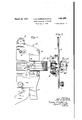
Fig. 1 is a side elevation of a check selecting apparatus of our invention, adapted particularly for the separation of United States five-cent coins from other coins or checks.
Fig. 2 is an end view thereof taken from the left side of Fig. 1.
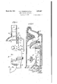
Fig. 3 is a vertical section of the apparatus on line 3-3 in Fig. 2. f
Fig. 4 is a transverse section on line 4-4 in Fig.3.
Fig. 5 is a partial side elevation of the apparatus showing a simple form of vending device associated therewith, and means for and having the desired weight will fo causing all deposited checks'to be returned when said vending machine is empty.
Fig. 6 is a view similar to Fig. 3 showing a modified form of the invention adapted particularly for separating of silver coins, such as United States twenty-five cent pieces, from other checks."
The apparatus shown in Figs. 1 to 4 inclusive comprises two vertically disposed parallel plates or side walls 1 and 2 spaced apart by a distance only slightly greater than the thickness of the checks to be selected so as to ermit such checks to pass therebetween. trips or. segments indicated at 26, 27, and 28 are secured in any suitable manner between certain edge portions of said plates and are so shaped as to cooperate with other parts hereinafter. described to define passages for conduction of the checks therethrou h. The side plate 2 is provided with an opening 3 adj acent its upper end of substantially the size and shape of the check to be selected. A vertical passage 4 extends downwardly from said opening. Positioned below this passage is a small permanent magnet 5 of modified horseshoe shape, whose upper arm 6 is inclined downwardly from a position beneath the passage 4 to the position of the poles 7 of said magnet, while the lower arm 8 is inclined in the reverse direction. Said magnet may be supported in any suitable manner, as by means of suitably shaped members 9 and bolts 10. The ends of the poles 7 of said magnet are preferably rounded somewhat as shown. The upper magnet arm 6 and the strip 26 cooperate to define a downwardly inclined entrance passage 11 leading from the bottom of passage 4 to a position adjacent the magnet poles 7. An arm 12 pivotally mounted at 13 so as to swing freely between the side plates 1 and 2 and in an opening 14 between the strips 26 and 27, is provided with a suitably shaped face 15 positioned opposite the lower end of passage 11. Said arm also has a projection 12 extending outside the casing, the purpose of which will be described hereinafter. A pin or other member 16 extends between the side plates 1 and 2 and acts as a stop to limit forward movement of arm 12, which is normally held by gravity in position against said stop.
Below the magnet 5 is provided a segment 17 having two upper face portions 18 and 19 inclined downwardly inopposite directions from a dividing point or edge 20. This dividing edge 20 is/positioned below and sufficiently beyond the magnet poles 7 so that a check possessing nonrmagnetic properties low a certain trajectory and pass beyond said dividing edge, while magnetic checks and checks sufliciently light in weight to be de-. flected to a relatively great extent by arm 12 will be caused to fall to the left of said dividing edge, as hereinafter described. The. up-
and which leads to a passage 22 between the forward end of segment 17 and strip 28. The
' The rear face 24 of so cut 17 is spaced from the inner face 25 o strip 27' by a distance substantially exactly equal to the diameter of the checks to be selected by the apparatus, so as to provide a passage 30 between said faces which is only of sufiicient width to permit vertical motion of a check therethrough; Strip 27 is provided with an in,-
ward projection 27' having an upper face portion 31 in position below the passage 30 so as to be struck by a check falling through said passage, this face portion 31 having a slight downward inclination in the reverse directionto the downward inclination of passage 11. From the forward edge of this slightly inclined face portion, a face 32 continues in this same direction at a somewhat greater inclination. The lower face 33 of segment 17 is spaced from face 32 by a distance sufficient to provide another intermediate check passage 34 therebetween, which is also inclined in the reverse direction to passage 11. However, we prefer to provide segment 17 with a bounding from said last named ace and tend hereinafter described.
Means are provided for creating a zone of concentrated magnetic flux across the passage 34 and preferably adjacent the lower. end thereof so as to permit the check to acquire a certain downward velocity in said passage before passing through said flux. Such fiux creating means may comprise a horseshoe magnet 37 whose arms 37a and 37b lie at opposite sides of the walls 1 and 2. Said mag-' net is shown as provided with pole pieces 38a and 38?) having projecting pole members extending through the side plates 1 and 2 respectively and directly opposite one another so that the check will be caused topass closely between said pole members. It will be understood that the side plates and other parts adjacent said. pole pieces are made of non-magnetic material or material of low magnetic permeability, while said pole pieces are made of material of high magnetic permeability,
to bring the check substantially to rest as such as iron, so that'the magnetic flux is conhave shown the same as secured by means of bolts .48 to a bracket 49 which is in turn secured by screws 51 to the side plate 1.
The pole member of pole piece 38a is shown as comprising a short cylindrical portion 39a formed integrally therewith and extending through the plate 1, but the pole member of pole piece 38?) is shown as adjustable. Such adjustable pole member is shown as comprising a screw 39?) adjustably mounted in an internally threaded recess 390 in pole piece 385. Said pole piece also has an integral ring-shaped portion 39d extending inwardly through the side plate 2. Screw 39b is of such length that when screwed all the way in,
, that is, when its head engages the outer face of pole piece 385, its inner end is just flush with the inner face of projection 39d, and should not in any case project beyond this face. Said screw is slotted inwardly from its head end, as shown at 39c, and is sprung outwardly from said 'slot, so as to exert suflicient friction to hold the screw in any position to which it may be adjusted.
In assembling the apparatus, the magnet 37 is designed to have a magnetic force slightly greater than that required, and the screw 39?) is first screwed all the way in and is then backed out /so as to weaken the flux, until the desired selectivity is obtained. Also, after the device has been in use for some time, the magnet may become slightly weakened,
whereupon said screw maybe moved inwardly to again restore the flux density to the desired value. It is evident that inward and outward movement of said screw will re spectively decrease and increase the magnetic reluctance of the gap between the o posing pole members, and thus adjust the flux density to the desired value. The ability to thus adjust the intensity of the-magnetic flux after the device is assembled, and from time to time during theoperation thereof, has been found to be of very great advantage in insuring the proper selective action at all times.
The inc-lined face 32 terminates at 41 and from this point the check is allowed to fall in a free trajectoryv through a space 42, such trajectory depending upon the velocity of the check after passing through the magnetic flux. An anvil or impact member 43 is mounted beneath thisspace, said anvil having an inclined impact face 44 in position to be struck only by checks following certain traj ectories through said space. Rearwardly of said impact member there is provided an im proper check outlet passage or chute 45 to receive checks falling short of said impact member and checks striking said impact member but failing to rebound in the proper manner, and to also receive checks delivered through space 42 from passage 22. In order to direct these last mentioned-checks away from the impact member and into passage 45, the strip 28 is provided with a suitably curved shoulder 46. Passage 45 may lead to any suitable means for disposition of improper checks, for example, to a return chute 47 leading to a point outside the housing in which the device is mounted, for returning such checks to the person by whom they were deposited.
At the opposite side of passage 45 from the impact member there is provided a barrier plate 53 preferably having a sharp pointed upper edge 54. An outlet passage 55 for proper checks is provided between said barrier plate and the lower end portion 27" of strip 27. Said passage may lead to'any suitable means for disposition of proper checks, and is shown, for example as connected to a chute 58 which, when the device is used in conjunction with a vending machine or the like, may lead to the check control mechanism of such machine.
In, order to provide a further selective action on the checks rebounding from said impact member, We' refer to provide another swinging arm 56 0 suitable light weight ma terial, pivotally mounted at 57 and normally hanging in position across the opening above the barrier plate-53. The weight of said arm is such that a check of proper weight will, upon striking said arm, swing the same back out of its path and enter passage 55, while a into passage v4 and thence into the down-' wardly inclined entrance passage 11. Rolling downwardly over the upper arm 6 of magnet 5, said check is brought'into close proximity to the magnetic pole pieces 7, so that if it is made of iron or contains sulficient iron or other paramagnetic material to be appreciably attracted by said pole pieces, it will be caused to adhere thereto, or be deflected thereby, and will roll around the ends of the pole pieces and under the lower arm 8, where the magnetic field is weakened to-such an extent as to permit the check to drop at some position to the left of the dividing edge 20. The check will then roll downwardly in passage 21 and fall through passage .22 and will be deflected by shoulder 46 so as to enter passage 45. 1
Checks which are not thus magnetically attracted by the pole pieces 7 will, by reason of the momentum which they acquire in the passage 11 will be projected over such pole pieces and will strike arm 12.
If the check is of materially less than proper weight it will be deflected by arm 12 and caused to fall to the left of dividing edge 20 and will thus be delivered as before through passages 21, 22 and 45. Furthermore, checks such as those consisting partly of iron, which are slightly magnetic but are insufliciently so to be deflected into chute 21 by the magnet-alone, and which are of substantially correct weight or only slightly underweight and hence would not be deflected into said chute by the arm 12 alone, will nevertheless be deflecteddnto said chute by the combined action of said arm and magnet. Checks striking said arm are still with- I 4 in the field of said magnet, and the slight retardation thus eflected, together with the retarding effect of such magnetic field, will act together to deflect such checks sufiicient ly to cause the same to fall to the left of edge 20. v V a However, if a check is of proper weight and non-magnetic its momentum will be sufficient to swing said arm out of the way with but I slight retardation, and the check will pass on through the space 23 into the vertical passage 30. Upon entering the vertical passage whose width is substantially the width of the checks to be selected, the check will lose its horizontal component of motion and will be caused to pass straight vertically downward through said passage, the height of said passagebeing sufiicient to prevent any check from striking the further wall thereof and rebounding through the passage without again striking ,the nearer wall and being thus constrained to move vertically downward. This construction, therefore, insures that all checks are delivered onto the slightly inclined face 31 without any horizontal component of motion, regardless of the force with which they may have been delivered into the apparatus. Furthermore,
' zone of magnetic flux between the pole members of pole pieces 39a and 396, the check will be more or less retarded by such magne'tic flux, in accordancewith the magnetic and electrical properties of the check. With the apparatus shown in these-figures, if the check possesses the proper magnetic and electrical properties its motion will be retarded to a relatively small extent and the velocity with which it leaves passage 34 will, therefore, be
suflicient to cause it to fall in a certain trajectory and strike upon the impact face 44. However, other metal checks will be retarded to a greater extent and will be caused to follow such a trajectory as to fall short of said impact face and enter passage 45.
Furthermore, any check striking the impact face 44 will rebound therefrom in a path dependent on the position of impact and upon its resilience. A check having the proper position of impact on said face and possessing the proper resilience will be caused to re-' bound sufliciently to clear the upper edge 54 of barrier 53, and if such check also possesses the proper weight it will swing the arm 56 aside and pass on into the outlet passage 55,- and thence through chute 58 to the check control mechanism or other means for further disposition thereof. If, on the other hand, said check fails to strike properly on the impact member and fails to possess the proper resilience, it will rebound therefrom to a less extent and will enter passage 45. Furthermore, even though the check should rebound in the proper path to clear the top of the barrier member, if its weight is insufficient it will be deflected by arm 56 and thrown back into the passage 45. It will be seen that the above arrangement provides for two complete reversals in horizontal direction of motion of the check in passing through the apparatus, and while the improper checks may be separated from the proper. checks at any one of a plurality of points in the path followed by proper checks, the construction also provides for delivery'of all improper checks, regardless of the particular point where they may be rejected, through one common improper check outlet passage. From said passage such checks are all returned through chute 47 to the deposited. a v
This arrangement of parts providing for zig-zag passage of the cheeks through the apparatus is advantageous in that it permits the horizontal dimension of the apparatus in person whom they were the plane of travel of the checks to be much less than would be the case if. the checks were caused to travel continuously in one horizontal direction through the apparatus. It provides-a much more compact check selecting device than anydevices heretofore used and adapted'to perform an equivalent number of selective actions on the checks. 6
In Fig. 5, a check selecting device as above described, is indicated at A and is shownassociated with a simple form of vending aptom-most article 62 may be delivered. For
effecting such delivery any suitable means may be provided, but we have shown such means as comprising a lever 64 pivotally mounted at 65 and'provided with an extension 66 passing through an opening 67 .in the rear wall of easing 61-and adapted to push the bottom-most article forwardly and deliver the same through chute 63. It will sertion otfla check in the check selecting de-.
vice and delivery thereof through the proper check outlet passage 55 above described.
For the purpose of insuring return of a deposited check to the person depositing the same, when the last article of merchandise has been delivered from the vending machine, we have shown a lever 69 pivotally mounted at 71, with its lower end7 2 extending adjacent the projecting portion 12' of arm 12 and provided at its upper end with a lug 73 extending through an opening 74 in the rear wall of casing 61. A tension spring 75 is provided tending to move the upper end of lever 69 forwardly, but such forward movement is normally prevented by engagement of lug 73 with the rear face ofthe articles 62. A suitable weight 75 is shown as provided on top of the stack of articles 62, in order to insure that the articles will be fed successively downwardly in easing 61 as each article is delivered from the bottom of the stack. The lower end 72 of lever 69 is normally spaced sufficiently from projection 12 to permit free swinging of arm 12, through a sufficient angle toallow the checks to pass said arm.
It will be seen, however, that when the last of the articles 62 has been delivered from casing 61, and the weight 75 has reached the bottom of said casing and passed below lug 73, the lever 69 and said lug will be moved by spring 75 to the positions indicated at 69' and 7 3' thus bringing the lower end of said lever into engagement with projection 12' so as to prevent normal swinging of arm 12 and lock the same sub; stantially in the position shown in Fig. 3. With said arm locked in this position, any check deposited through opening 3 into the check selecting device will be deflected by said arm and caused to pass through passages 21 and 22 to the improper check outlet passage 25 whence it will be returned to the person depositing the same through the return chute 47.
The form of apparatus shown in Fig. 6 is designed for the separation of silver coins, such as United States twenty-five cent pieces from other coins and checks, the essential difference between this form and the form of apparatus first described being that in the first case there is no provision for checks following such a trajectory as to pass beyond the impact means, while in this modified form of apparatus such provision is made. This is for the reason that the first apparatus is designed for the selection of United States five cent pieces which have been I found to undergo a less reduction in velocity .on passage through the magnetic flux than any other common metal checks. In case of silver coins, on the other hand, such coins undergo a greater reduction in velocity on passage through said magnetic flux than do certain other metal checks and therefore fall in shorter trajectories than such other checks; The apparatus shown in Fig. 6 .is
similar in most respects to that above de scribed. with the exception that the impact member 43' is somewhat differently posi tioned with respect to the lower end of passage 34, so as to be struck by cheeks following relatively short trajectories, and a passage 45a is provided beyond said impact member for receiving checks following longertrajectories. A second passage 45?) is also provided at the other side of said impact member, principally for receiving checks striking said impact member but having less than the proper resiliency. There is provided as before a barrier member 53 whose upper edge 54"is so positioned that only the checks possessing proper resiliency will rebound thereover. A proper check outlet passage 55 is provided at the further side of said barrier for receiving and carrying away the proper checks. The passages 45a and 45b for improper checks both lead to a common return chute or other passage means 47. In this case the intermediate passage 21 for magnetically attracted checks is shown as leading to a passage 22 whose lower end is open straight downwardly toward the passage 45a, so that the magnetically attracted checks will fall through said passage 45a. It will be understood, of course, that a swinging arm for deflecting light weight checks rebounding from the impact member, similar to the arm 56 in the tion is similar to that above described, with the exception that the proper cheeks, namely, United Statestwenty-five cent pieces, are retarded to a relatively great extent on passing through the zone of magnetic flux and are hence caused to'fall in a short trajectory and strike the impact face 44' of the impact member. Due to their relatively high resilience, said checks then rebound in such a path asto pass over the barrier edge 54' and into'the passage 55. Checks undergoing a lesser retardation on passing through the magnetic flux, on the other hand, follow a relatively longer trajectory and pass beyond the impact member into passage 45a, while checks striking said-impact member but failing to rebound suffieiently fall, as before, into passage 45?).
We claim:
1. In a check selecting apparatus, means defining a downwardly inclined entrance passage for checks having means for insertion of checks into the upper end thereof, means defining two separate intermediate check passages downwardly inclined in the reverse direction to'said entrance passage and beneath the same, the upper ends of bothof said in termediate passages being in communication fining a space through which checks leaving said last-mentioned passageway may fall free- -1y in a trajectory dependent upon their velocity, impact means beneath said space in position to be struck only by checks following certain trajectories, said space also permitting free rebound of checks from said impact member in accordance with the position of impact and the resilience thereof, means defining aproper check outlet passage whose entrance is positioned to receive only. checks rebounding in certain paths from said im pact member, and means defining an improper check outlet passage whose entrance is positioned to receive checks passing through the intermediate passage for improper checks, and to also receive checks leaving the intermediate passage for proper checks but failing to strike said impact means and checks striking said impact means but failing to rebound therefrom in said certain paths.
.2. An apparatus as set forth in -claim 1,
in which the selecting means adjacent the lower end of the entrance passage comprises a magnet whose poles areso positioned as to cause magnetically attracted checks passing the same to be delivered into the intermediate passage for improper checks, and to permit other checks to be delivered into the inter mediate passage for proper checks.
3. An apparatus as set forth in claim 1, in which the means associated with the proper check intermediate passage for influencingthe velocity "of checks passingtherethrough comprises meanscreating a zone of magnetic flux extending across said passage at a distance from the upper end of saidpassage.
4. An apparatus comprising, in combina tionwith a vending machine having a'receptacle for articles and means for successively discharging said articlesfrom said receptacle, means definin a downwardly inclined entrance passage or checks, at ivotally mounted arm positioned opposite t e lower end of said passage in position to be engaged by checks leaving said passage and adapted to permit passage thereby of checks having means defining a separate passage in position to receive checks deflected by said arm, means for returning to a point of access from outside the vending machine checks entering said last-named passage, and means engaging the articles in said receptacle and operable upon discharge of the .last of said articles therefrom to engage said'arm and prevent swinging thereof so as to thereupon cause all checks leaving said entrance passage to be deflected and delivered through said check return means.
5. In a check selecting apparatus, means defining a downwardly inclined check conducting passage, a magnet positioned-adjacent said passage in such position as to deflect magnetically attracted checks from said passage, means defining a passage positioned to receive checks so deflected, means defining a vertically extending check conducting pas sage communicating with said downwardly inclined passage at a position beyond said magnet so as to receive checks not deflected by said magnet, the width of said vertical passage being substantially exactly equal to the diameter of the checks to be selected, and the length of said vertical passage being suificient to suppress any horizontal component of motion of checks delivered thereto and thereby cause said checks to be delivered substantially vertically at the lowerend of said verticalextending passage, means defining another ownwardly inclined check conducting passa e communicating with the lower end of said vertically extending passage, means creating a zone of magnetic flux across said last named downwardly inclined passage at a point below the point of communication thereof with said vertically extending passage, means defining a space beneath the lower end of said last named downwardlfy inclined passage to permit acheck to fall reely from said passage through said space, and means positioned within said space for selectively separating checks in accordance with the velocity at which saidche'cks leave said last named inclined passage.
inclination and a check guiding portion of relatively large inclination extendmg downwardly from the lower end of said impact receiving portion, means defining a vertical passage communicating with the up er end of said inclined passage and adapter? to deliver checks vertically upon said impact receiving face, portion, said passage defining means including a shoulder positioned above vsaid downwardlyiinclined passage and adjacent the junction thereof with said vertical passage and in position to be engaged by checks rebounding from said impact receiving face portion, said impact receiving face portion and said shoulder being adapted to cooperate to bring all checks substantially to a stop at this point, means creating a zone of magnetic flux across said downwardly inclined passage at a distance from the upper end thereof, and means beyondthe lower end of said downwardly inclined passage and operable to selectively separate checks in accordance with the velocity at which said checks leave said downwardly inclined passa e.
g In a check selecting apparatus, means defining a downwardly extending check conducting passage, magnet means of horseshoe shape having arms disposed at opposite sides of said passage, pole members mounted on the a respective arms in position, to define a gap across said passage, one of said pole members comprising a member ad ustably mounted on its respective magnet arms so as to .pera ber, 1929.
- HUGH E. WURZBACH. Q LESLIE H. WADSWORTH.
Priority Applications (1)
| Application Number | Priority Date | Filing Date | Title |
|---|---|---|---|
| US411807A US1851557A (en) | 1929-12-05 | 1929-12-05 | Check selecting apparatus |
Applications Claiming Priority (1)
| Application Number | Priority Date | Filing Date | Title |
|---|---|---|---|
| US411807A US1851557A (en) | 1929-12-05 | 1929-12-05 | Check selecting apparatus |
Publications (1)
| Publication Number | Publication Date |
|---|---|
| US1851557A true US1851557A (en) | 1932-03-29 |
Family
ID=23630413
Family Applications (1)
| Application Number | Title | Priority Date | Filing Date |
|---|---|---|---|
| US411807A Expired - Lifetime US1851557A (en) | 1929-12-05 | 1929-12-05 | Check selecting apparatus |
Country Status (1)
| Country | Link |
|---|---|
| US (1) | US1851557A (en) |
Cited By (3)
| Publication number | Priority date | Publication date | Assignee | Title |
|---|---|---|---|---|
| US2763356A (en) * | 1954-07-15 | 1956-09-18 | Seth B Atwood | Coin testing device |
| US3010556A (en) * | 1954-09-28 | 1961-11-28 | William J Wawrzonek | Refrigerated food vender |
| US3672481A (en) * | 1968-12-06 | 1972-06-27 | Coin Verifiers Co Ltd | Variable magnetic flux coin-sensing devices |
-
1929
- 1929-12-05 US US411807A patent/US1851557A/en not_active Expired - Lifetime
Cited By (3)
| Publication number | Priority date | Publication date | Assignee | Title |
|---|---|---|---|---|
| US2763356A (en) * | 1954-07-15 | 1956-09-18 | Seth B Atwood | Coin testing device |
| US3010556A (en) * | 1954-09-28 | 1961-11-28 | William J Wawrzonek | Refrigerated food vender |
| US3672481A (en) * | 1968-12-06 | 1972-06-27 | Coin Verifiers Co Ltd | Variable magnetic flux coin-sensing devices |
Similar Documents
| Publication | Publication Date | Title |
|---|---|---|
| US2292628A (en) | Coin selector | |
| US2339823A (en) | Coin detector | |
| US1851557A (en) | Check selecting apparatus | |
| US2763356A (en) | Coin testing device | |
| US2277018A (en) | Coin chute | |
| US2233654A (en) | Coin chute | |
| US2588510A (en) | Multiple coin selector | |
| US2339695A (en) | Coin selector | |
| US2026262A (en) | Check selecting apparatus | |
| US2343352A (en) | Coin selector for coin controlled machines | |
| US2528690A (en) | Paramagnetic coin separator | |
| US2975880A (en) | Coin separator and slug ejector | |
| US2057737A (en) | Detecting apparatus | |
| US2009609A (en) | Separating apparatus and method | |
| US1956066A (en) | Coin selecting device | |
| US1693104A (en) | Method and apparatus for selecting metal checks | |
| US1839874A (en) | Fraud preventing device | |
| US3452849A (en) | Magnetic coin tester | |
| US2279488A (en) | Coin chute | |
| US1970005A (en) | Multiple coin separator | |
| US2538820A (en) | Coin selector for coin-controlled machines | |
| US1892777A (en) | Spurious coin detector | |
| US2745531A (en) | Anti-cheating device coin operated machines | |
| US2158909A (en) | Coin and slug separating device | |
| US1732826A (en) | Method and apparatus for selecting checks |