US1851555A - Tire carcass and rubber reclaiming machine - Google Patents
Tire carcass and rubber reclaiming machine Download PDFInfo
- Publication number
- US1851555A US1851555A US36748129A US1851555A US 1851555 A US1851555 A US 1851555A US 36748129 A US36748129 A US 36748129A US 1851555 A US1851555 A US 1851555A
- Authority
- US
- United States
- Prior art keywords
- tire
- head
- disposed
- driving
- cutter
- Prior art date
- Legal status (The legal status is an assumption and is not a legal conclusion. Google has not performed a legal analysis and makes no representation as to the accuracy of the status listed.)
- Expired - Lifetime
Links
- 230000007246 mechanism Effects 0.000 description 6
- 238000000034 method Methods 0.000 description 4
- 239000004744 fabric Substances 0.000 description 3
- 244000261422 Lysimachia clethroides Species 0.000 description 2
- 241001300059 Theba Species 0.000 description 2
- 210000005069 ears Anatomy 0.000 description 2
- MCNQUWLLXZZZAC-UHFFFAOYSA-N 4-cyano-1-(2,4-dichlorophenyl)-5-(4-methoxyphenyl)-n-piperidin-1-ylpyrazole-3-carboxamide Chemical compound C1=CC(OC)=CC=C1C1=C(C#N)C(C(=O)NN2CCCCC2)=NN1C1=CC=C(Cl)C=C1Cl MCNQUWLLXZZZAC-UHFFFAOYSA-N 0.000 description 1
- 241001421757 Arcas Species 0.000 description 1
- HEFNNWSXXWATRW-UHFFFAOYSA-N Ibuprofen Chemical compound CC(C)CC1=CC=C(C(C)C(O)=O)C=C1 HEFNNWSXXWATRW-UHFFFAOYSA-N 0.000 description 1
- 229910000831 Steel Inorganic materials 0.000 description 1
- 239000011248 coating agent Substances 0.000 description 1
- 238000000576 coating method Methods 0.000 description 1
- 238000010276 construction Methods 0.000 description 1
- 230000001050 lubricating effect Effects 0.000 description 1
- 238000004519 manufacturing process Methods 0.000 description 1
- 239000000463 material Substances 0.000 description 1
- 239000010959 steel Substances 0.000 description 1
Images


Classifications
-
- B—PERFORMING OPERATIONS; TRANSPORTING
- B29—WORKING OF PLASTICS; WORKING OF SUBSTANCES IN A PLASTIC STATE IN GENERAL
- B29B—PREPARATION OR PRETREATMENT OF THE MATERIAL TO BE SHAPED; MAKING GRANULES OR PREFORMS; RECOVERY OF PLASTICS OR OTHER CONSTITUENTS OF WASTE MATERIAL CONTAINING PLASTICS
- B29B17/00—Recovery of plastics or other constituents of waste material containing plastics
- B29B17/02—Separating plastics from other materials
- B29B17/0206—Selectively separating reinforcements from matrix material by destroying the interface bound before disintegrating the matrix to particles or powder, e.g. from tires or belts
-
- B—PERFORMING OPERATIONS; TRANSPORTING
- B29—WORKING OF PLASTICS; WORKING OF SUBSTANCES IN A PLASTIC STATE IN GENERAL
- B29K—INDEXING SCHEME ASSOCIATED WITH SUBCLASSES B29B, B29C OR B29D, RELATING TO MOULDING MATERIALS OR TO MATERIALS FOR MOULDS, REINFORCEMENTS, FILLERS OR PREFORMED PARTS, e.g. INSERTS
- B29K2021/00—Use of unspecified rubbers as moulding material
-
- B—PERFORMING OPERATIONS; TRANSPORTING
- B29—WORKING OF PLASTICS; WORKING OF SUBSTANCES IN A PLASTIC STATE IN GENERAL
- B29L—INDEXING SCHEME ASSOCIATED WITH SUBCLASS B29C, RELATING TO PARTICULAR ARTICLES
- B29L2030/00—Pneumatic or solid tyres or parts thereof
-
- Y—GENERAL TAGGING OF NEW TECHNOLOGICAL DEVELOPMENTS; GENERAL TAGGING OF CROSS-SECTIONAL TECHNOLOGIES SPANNING OVER SEVERAL SECTIONS OF THE IPC; TECHNICAL SUBJECTS COVERED BY FORMER USPC CROSS-REFERENCE ART COLLECTIONS [XRACs] AND DIGESTS
- Y02—TECHNOLOGIES OR APPLICATIONS FOR MITIGATION OR ADAPTATION AGAINST CLIMATE CHANGE
- Y02W—CLIMATE CHANGE MITIGATION TECHNOLOGIES RELATED TO WASTEWATER TREATMENT OR WASTE MANAGEMENT
- Y02W30/00—Technologies for solid waste management
- Y02W30/50—Reuse, recycling or recovery technologies
- Y02W30/62—Plastics recycling; Rubber recycling
-
- Y—GENERAL TAGGING OF NEW TECHNOLOGICAL DEVELOPMENTS; GENERAL TAGGING OF CROSS-SECTIONAL TECHNOLOGIES SPANNING OVER SEVERAL SECTIONS OF THE IPC; TECHNICAL SUBJECTS COVERED BY FORMER USPC CROSS-REFERENCE ART COLLECTIONS [XRACs] AND DIGESTS
- Y10—TECHNICAL SUBJECTS COVERED BY FORMER USPC
- Y10T—TECHNICAL SUBJECTS COVERED BY FORMER US CLASSIFICATION
- Y10T409/00—Gear cutting, milling, or planing
- Y10T409/30—Milling
- Y10T409/309296—Detachable or repositionable tool head
-
- Y—GENERAL TAGGING OF NEW TECHNOLOGICAL DEVELOPMENTS; GENERAL TAGGING OF CROSS-SECTIONAL TECHNOLOGIES SPANNING OVER SEVERAL SECTIONS OF THE IPC; TECHNICAL SUBJECTS COVERED BY FORMER USPC CROSS-REFERENCE ART COLLECTIONS [XRACs] AND DIGESTS
- Y10—TECHNICAL SUBJECTS COVERED BY FORMER USPC
- Y10T—TECHNICAL SUBJECTS COVERED BY FORMER US CLASSIFICATION
- Y10T82/00—Turning
- Y10T82/25—Lathe
- Y10T82/2531—Carriage feed
- Y10T82/2541—Slide rest
Definitions
- a further primary object of the invention is for the reclaiming of the rubber in'highly usable form which consists primarily in the cutting of the tread portion of the tire into ribbon-like strips.
- In-my new and improved device'I mount the'tire to be treated upon an expansible rotating element and provide means for driving the same.
- the device in preferred embodiment, consists ofan annular driven wheel over which the .tireto be treaded is placed.
- a plurality of other supports are mounted upon a frame with means for adapting the supports to theinner surface of thetire so that the same may be substantially stressed to facilitate the rotation of the driving wheel and of' the tire, the tire being driven. by frictional. engagement with the driving or in the manufacturing of boots, insoles and 1929.
- a removable cylindrical lubricated cutter-head is arranged tangential, or substantially tangential; of the wheel and is arranged for engaging the tread ortion of the tire and for being manually fe in glriven engagement with the tread portion of the tire .to cut the tread portion from the tire in strips or ribbons.
- the cutter-head is power driven and manually manipulated.
- the supports for the tire carcass are of a sha size to expand the smaller of the tires to increasetheir cross-sectional diameter to that of the largest tire to which the driving wheel is to beused.
- the ribbon cut from the tire carcass is permitted to flow throu h the internal passage disposed within t e cutterhead.
- Simple means are provided to facilitate the removal of the cylindrical cutter blade from the driven head. The same is adapted to the driving head to facilitate a uick change of the cutter-head from the rivin g head.
- I preferably form my device of a rigid, ,framed structure to which the associated moving parts are supported.
- the power units for driving the mechanisms are removably disposed upon and within theframe, in order to compose a completely assembled unit that will be compact .and easily moved.
- One of the primary objects of my device is to reclaim the tire treads of used tires and to remove the reclaimed rubber in ribbon form in order that the same may be easily and uni: formly treated for reuse.
- a further object is to leave the tire carcass in uniform shape. andcondition in order that thesame may be retreaded to give uniform results.
- the methods employed in the reclaiming of the tire tread have not left the tire carcass in uniform condition.
- the retreading of the tire carcasses did not reduce tires of uniform size, appearance an homogeneity.
- a further object of my invention is to pro vide a machine that will rapidly remove and reclaim, in usable form, the tread portion of the tire.
- Astillgfurther object of my invention consists in providing means for the reclaiming of a tire carcass that leavesthe tire carcass in uniform surface condition and that do not in any. way disrupt or destroy the component elements comprising the same.
- a still further objectof my invention resides in a'machine that may be operated with a minimum of mechanical skill and with a minimum of personal labor or efiortr tures of construction and combination of parts, the essentialelements of which are set forth in the appended claims, and a preferred form of embodiment of which is hereinafter shown with reference to the drawings which accompany and form a part of this specification.
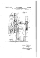
- Fig. 1 is a side elevation of the assembled device.
- Fig. 2 is a front, end view, partially in sectionof the assembled device.
- Fig. 3 is a top, plan view of the assembled device.
- Fig. 4 is a fragmentary, sectional, side view f t e cutter-head, the driving elements therefor, and of the driving wheel-over which the tire is placed and stressed.
- Fig. 5 is a sectional, side view, of the cutter-head and the driving mechanism therefore,'the same being taken on line 5-5 of Fig.4looking'in the direction indicated.
- j ig. 6 is'a sectional view of the rim of the driving wheel illustrating a tire disposed thereupon and illustrating the cutter-head in engagement with the tread portion of the tire.
- Fig. 7 is a side view of one other of the supporting wheels or heads adapted for engagement withvthe inside surface of the tire and illustrating a tire in cross section disposed thereupon.
- Fig. 8 is a fragmentary, side view of the I cutter-head illustrating means for lubricating or moistening the same.
- Fig. 9 is a top, plan view of the cutter- 'the shield disposed within the cutter-head.
- I' preferably form my device of a frame having a base 1, upwardly extending. end walls 2 and 3 and having side walls formed integral therewith to form a boxlike structure.dis'posed upon the base.
- a 'journaled bearing 4 is disposed horizontally within the frame throughwhich a driven main shaft 5 passes.
- a driving wheel ,6 is dsposed upon one end of the shaft 5 over which the tire c'arcass to be treated is placed and stressed.
- the diameter of the driving wheel 6 is substantially smaller than the diameter of the driving wheel may be made to adapt itself to the smallest and largest sizes of pneumatlc tires. Disposed in driving alignment with that of the driving wheel 6,]a-re a plurality.
- the head consistsof a goose-neck support 7 and has a central wheel 8 rotatably mounted upon a journal in 9 disposed within bosses 10 and 11.
- Si e wheels 13 and 14 engage the inner side wall portions of the tire and the wheel 8 engages the inner central portion of the tire.
- the side wheels 13 and 14 are journaled upon journal pins 15 and 16 that are secured to the cross bar 16A of the support 7.
- a bracket 17 is disposed disposed within the bracket.
- Bell crank arms 21 and 22 are pivotally disposed aboutthe stub shafts 19 and 20. The outer end of the arms 21 and 22 carry the head frames 23 and 24 on which the wheels 8, 13 and 14 are rotatably supported and the arms 25 and 26 carry camming pins 27 and 28.
- the adjustablecam head 29' is supported within the head block 30A and a dove-tailed connection is disposed between the camming head and the head block as illustrated at 31 in Fig. 2 and a reciprocating motion is imparted to the cam'ming head 29 by the adjusting lever '30.
- the adjusting and positioning lever 30 has a link 31A that indirectly connects the.
- Positioning slots 32 and 33 aredisposed within the camming head into which the pins 27 and 28 engage.
- Links 34 and 35 connect the wheel supporting heads 23 and 24 through the pinconnections 36 and 37 to bosses outwardly extending from the main frame.
- a bracket 38 is secured to the camming head 29 and the bracket carries a central wheel 39 and side and outwardly extends from the rear wall 18 of the frame and stub shafts 19 and 20 are wheels 40 and 41 to create a head similar to that at 23 and 24.
- the adjusting and positionin lever should be of a sufficient len h to ena Ie the operator to stress the tire being reconditioned and treated to afford a driving, frictional engagement between the tire and the driving "wheel 6 to which the driving motive power is applied to rotate the tire for'treatment.
- the bracket 38 supportingthe wheels 39, 40 and 41 is fixedly disposed upon the camining head 29 and as the camming head 29 is moved by the hand lever 30 the wheel heads and the wheels secured thereto are made to engage the inner surface of the tire and to tension-the tire placed therearound relative to the driving wheel 6 sufliciently to permit the'driving wheel 6 to drive the tire in rotation.
- a driving gear 42 is secured to the shaft 5 and a secondary driving shaft 43 is journaled within suitableibearings in the frame with a pinion 44 secured to the shaft 43, coacting with and driving the main gear .42.
- a drivin pulley 45 is disposed-upon the shaft 43 an a driving element 46 is trained around the driving pulley 45 and a driving ulley 47 is disposed upon the armature shag: 48 of the electric motor 49.
- a table 50 terminates the upper end of the sleeve support 77 illustrated in Fig, 1.
- the table 50 is disposed adjacent the frontof. the frame of the device and a base 51 is slidably disposed upon the table.
- Theba'se 51 is adapted to bereciprocated or .or positioned' upon the table 50 through themedium of a crank 52 secured to the outer end of the adjustingscrew 53.
- the adjusting screw'53 engages with the threaded block 54 that is secured to. the base 51.
- An inand out movement is imparted toithe base'51 relative. to the table 50 through the hand manipulation of the adjusting lever and screw.
- An electric motor 55 is disposed upon theba's'e'51 and "has a beveled driving pinion 56 secured tothe armature shaft 57.
- a hearing hub 58 is attached to the upper surface of the base 51 and is removably secured thereto by countersunk screws. 59 and a frictionless bearing 60 is disposed within the hub.
- a hollow shaft 61 is secured to the frictionlessbearing 60 and a cover-box 62 covers the frictionless bearing to maintain the same in a clean operating condition.
- a beveled gear 63 coacts with the driving beveled gear 56 and rotates the hollow shaft 61 and is secured thereto.
- a housing 64 bifurcated upon its lower end at 65, 66 is secured to the base 51 that acts as a hearing through which the hollow shaft passes and maintains the same in position and alignment.
- the hollow shaft 61 terminates in a 'driving head 67 upon its upper end.
- A'cylindrical cutter blade 68 is removably secured to the driving head 67 I have found good results may be obtained wherein the cutter blade is made from cold drawn steel seamless tubing. Thecharacter of the work required necessary to maintain the cutting blade in amoist or lubricated condition. I accomtrated in Fig.
- a cock 76 is disposedwithin the pipe line for plish this result by placing a shield as illusregulating the quantity of material to be d-eupon which the motor assembly and cutter and adjusting head is disposed is journa'ed about the vertical shaft 78 and the shaft 78 issecured (not shown) to the hub 7 9 that rests ,upon the base 1 'of the device.
- the driving wheel is an arc of a circle so that the inner surface of a tire mounted thereon' is brought to substantially the arc of a circle in horizontal cross section and the cen-' ter line of the supporting journal shaft 78 is disposed substantially vertical to and passing through .the radial center of the circle of the rim of the driving wheel 6 so that when the. depth of the cut is predetermined by the hand adjusting screw 53, the partial rota- .1
- cutter head trims the carcass of theitire to a ⁇ obtained quickly through the use of the adjusting handle 52 and the screw' 53.
- To ac-' link 82 thereby moving the whole assembly 4 along the supporting table 50.
- a dove-tailed connection is disposed between the table 51 and the guide bar 87.
- a frame means disposed upon the frame for mounting a tire thereon.
- a power driven driving wheel rotatably disposed on the frame for rotating the tire when mounted, a plurality ofsecondary wheels disposed in driving alignment with the driving wheel and adapted to be placed within the tire being detreaded, meansfor setting the secondary'wheels to adapt them to the diameter of,
- a cutter head removably secured to a hollow driving shaft, means for maintaining the cutter head in a wet condition.
- means for rotating thehollow driving shaft and the'cutter head, means for moving the cutter head toward and away from a tire to be reconditioned, means for moving the cutter head in the are of-a circleconcentric with the cross sectional surface of the driving wheel relative to a fixed support and means for driving the tire to be detreaded past the cutter head.
- a base means forsupporting the base to permit the base to be moved in a horizontal plane in the arc of a circle about the supporting means, a cutter head disp osed vertically upon the base, power means for driving the cutter head, means for moving the cutter head along the base, means for supporting a tire so that the radial center of the cross-section coincides with the center of combination of adjustable tire supporting means, means for rotating a tire in its normal plane of rotation, a ho ow shaft disposed vertically to the tread of the tire, a cutter head disposed about the hollow shaft in tan-.
- a device of the class described in combination with an adjustable tire mounting "frame adapted-to rotatably support a tire with its axis horizontal, a base, a shaft vertically positioned on the base so that it is aligne with the radial center of the arc of-a circle made by horizontal cross section through the axis of'the tire, a support made integral with the vertical shaft .housing, an adjustable base disposed upon the su port, a bifurcated housing, a bearing hub isposed 'therebetween a hollow shaft vertically disv means for moving the base in the arc of a circle relative to a fixed support.
- the- V combination with a tire cutting means with 1 an adjustable tire mounting frame, supporting heads comprising a goose neck support, a
- cross bar secured thereto, bosses disposed cen trally thereabove, a wheel rotatably j ournaled therebetween, and side wheelsrotatably journaled at each end of and under-the cross bar.
Landscapes
- Engineering & Computer Science (AREA)
- Environmental & Geological Engineering (AREA)
- Mechanical Engineering (AREA)
- Tyre Moulding (AREA)
- Tires In General (AREA)
Description
March 29, 1932- o. A. WHEELER TIRE CARGASS AND RUBBER RECLAIYIMING MACHINE 4 Sheets-Sheet. 1
Filed May 31, 1929 I VINVENIOR v 5 A111 u v March 29, 1932. o. A WHEELER 1,851,555
TIRE CARCASS AND RUBBER RECLAIMING MACHI NE Filed May 31, 1929 4 Sheets-Sheet 2 E I 471mm] 40 If V5/////F"'//// ////fA INVENTOR ATTO Y March 29, 1932. o. A. WHEELER TIRE CARCASS AND RUBBER RECLAIMING MACHINE Filed May 31, 1929 Omar If 1469/61? INVENTOR @hz BY March 29, 1932. o. A. WHEELER 1,851,555
TIRE CARCASS AND RUBBER RECLAIMING MACHINE Filed May 51, 1929 4 Sheets-Sheet 4.
lol
gnwnioz Patented Mar. 29,1932.
UNITED S TES PATENT OFFICE om n. wmmm, or 203mm, onmon '.I.IIZB1.'E CAROL AND BUBI BR BEOLAIHING CHINE Application filed Kay 81,
the like.
A further primary object of the invention is for the reclaiming of the rubber in'highly usable form which consists primarily in the cutting of the tread portion of the tire into ribbon-like strips. y
Heretofore it has been the general custom to pull the tread portion of the tire from the tire carcasswhich was a laborious task and which had a tendency to destroy the carcass portion of the tire. The reclaimed rubher was also'not in,as highly usable form as is obtained-through the use of my device,
In the reconditioning of the tread portion of the tire it is essential that the carcass remain in a uniform condition of thickness and be treated in a manner to leave such portions of the fabric'or cord as are to be used imbedded and impregnated within the rubber protecting coating. This is satisfactorily accomplished by the mechanism shown, described and claimed in my specification.
In-my new and improved device'I mount the'tire to be treated upon an expansible rotating element and provide means for driving the same. The device, in preferred embodiment, consists ofan annular driven wheel over which the .tireto be treaded is placed.- A plurality of other supports are mounted upon a frame with means for adapting the supports to theinner surface of thetire so that the same may be substantially stressed to facilitate the rotation of the driving wheel and of' the tire, the tire being driven. by frictional. engagement with the driving or in the manufacturing of boots, insoles and 1929. Serial No. 807,481
wheel. A removable cylindrical lubricated cutter-head is arranged tangential, or substantially tangential; of the wheel and is arranged for engaging the tread ortion of the tire and for being manually fe in glriven engagement with the tread portion of the tire .to cut the tread portion from the tire in strips or ribbons. The cutter-head is power driven and manually manipulated. The supports for the tire carcass are of a sha size to expand the smaller of the tires to increasetheir cross-sectional diameter to that of the largest tire to which the driving wheel is to beused. The ribbon cut from the tire carcass is permitted to flow throu h the internal passage disposed within t e cutterhead. Simple means are provided to facilitate the removal of the cylindrical cutter blade from the driven head. The same is adapted to the driving head to facilitate a uick change of the cutter-head from the rivin g head.
I preferably form my device of a rigid, ,framed structure to which the associated moving parts are supported. The power units for driving the mechanisms are removably disposed upon and within theframe, in order to compose a completely assembled unit that will be compact .and easily moved. One of the primary objects of my device is to reclaim the tire treads of used tires and to remove the reclaimed rubber in ribbon form in order that the same may be easily and uni: formly treated for reuse. w
A further object is to leave the tire carcass in uniform shape. andcondition in order that thesame may be retreaded to give uniform results. Heretofor'e the methods employed in the reclaiming of the tire tread have not left the tire carcass in uniform condition. By the old methods of tread removal, the retreading of the tire carcasses did not reduce tires of uniform size, appearance an homogeneity.
By my new and carcass is not permanently distorted and the methods and devices employed in the detreading process produce a tire carcass of uniform surface condition. v
A further object of my invention is to pro vide a machine that will rapidly remove and reclaim, in usable form, the tread portion of the tire.
Astillgfurther object of my invention consists in providing means for the reclaiming of a tire carcass that leavesthe tire carcass in uniform surface condition and that do not in any. way disrupt or destroy the component elements comprising the same.
A still further objectof my invention resides in a'machine that may be operated with a minimum of mechanical skill and with a minimum of personal labor or efiortr tures of construction and combination of parts, the essentialelements of which are set forth in the appended claims, and a preferred form of embodiment of which is hereinafter shown with reference to the drawings which accompany and form a part of this specification.
In the drawings: Fig. 1 is a side elevation of the assembled device.
Fig. 2 is a front, end view, partially in sectionof the assembled device.
Fig. 3 is a top, plan view of the assembled device.
Fig. 4 is a fragmentary, sectional, side view f t e cutter-head, the driving elements therefor, and of the driving wheel-over which the tire is placed and stressed.
Fig. 5 is a sectional, side view, of the cutter-head and the driving mechanism therefore,'the same being taken on line 5-5 of Fig.4looking'in the direction indicated.
j ig. 6 is'a sectional view of the rim of the driving wheel illustrating a tire disposed thereupon and illustrating the cutter-head in engagement with the tread portion of the tire.
Fig. 7 is a side view of one other of the supporting wheels or heads adapted for engagement withvthe inside surface of the tire and illustrating a tire in cross section disposed thereupon. I
, Fig. 8 is a fragmentary, side view of the I cutter-head illustrating means for lubricating or moistening the same.
Fig. 9 is a top, plan view of the cutter- 'the shield disposed within the cutter-head.
Like reference characters refer to like parts throughout the several views.
I' preferably form my device of a frame having a base 1, upwardly extending. end walls 2 and 3 and having side walls formed integral therewith to form a boxlike structure.dis'posed upon the base. A 'journaled bearing 4 is disposed horizontally within the frame throughwhich a driven main shaft 5 passes. A driving wheel ,6 is dsposed upon one end of the shaft 5 over which the tire c'arcass to be treated is placed and stressed. The diameter of the driving wheel 6 is substantially smaller than the diameter of the driving wheel may be made to adapt itself to the smallest and largest sizes of pneumatlc tires. Disposed in driving alignment with that of the driving wheel 6,]a-re a plurality.
of supporting heads two of which are made as illustrated in Fig. 7. The head consistsof a goose-neck support 7 and has a central wheel 8 rotatably mounted upon a journal in 9 disposed within bosses 10 and 11. Si e wheels 13 and 14 engage the inner side wall portions of the tire and the wheel 8 engages the inner central portion of the tire. The wheels 8, 13
and 14 are so placed in spaced relationship as to fit substantially the cross section of they 1 smallest tire to be treated, in order that the rim of the driving wheel '6. The side wheels 13 and 14 are journaled upon journal pins 15 and 16 that are secured to the cross bar 16A of the support 7. A bracket 17 is disposed disposed within the bracket. Bell crank arms 21 and 22 are pivotally disposed aboutthe stub shafts 19 and 20. The outer end of the arms 21 and 22 carry the head frames 23 and 24 on which the wheels 8, 13 and 14 are rotatably supported and the arms 25 and 26 carry camming pins 27 and 28. The adjustablecam head 29'is supported within the head block 30A and a dove-tailed connection is disposed between the camming head and the head block as illustrated at 31 in Fig. 2 and a reciprocating motion is imparted to the cam'ming head 29 by the adjusting lever '30. The adjusting and positioning lever 30 has a link 31A that indirectly connects the.
A table 50 terminates the upper end of the sleeve support 77 illustrated in Fig, 1. The table 50 is disposed adjacent the frontof. the frame of the device and a base 51 is slidably disposed upon the table. I Theba'se 51 is adapted to bereciprocated or .or positioned' upon the table 50 through themedium of a crank 52 secured to the outer end of the adjustingscrew 53. The adjusting screw'53 engages with the threaded block 54 that is secured to. the base 51. An inand out movement is imparted toithe base'51 relative. to the table 50 through the hand manipulation of the adjusting lever and screw. An electric motor 55 is disposed upon theba's'e'51 and "has a beveled driving pinion 56 secured tothe armature shaft 57. A hearing hub 58 is attached to the upper surface of the base 51 and is removably secured thereto by countersunk screws. 59 and a frictionless bearing 60 is disposed within the hub. A hollow shaft 61 is secured to the frictionlessbearing 60 and a cover-box 62 covers the frictionless bearing to maintain the same in a clean operating condition. A beveled gear 63 coacts with the driving beveled gear 56 and rotates the hollow shaft 61 and is secured thereto. A housing 64 bifurcated upon its lower end at 65, 66 is secured to the base 51 that acts as a hearing through which the hollow shaft passes and maintains the same in position and alignment. The hollow shaft 61 terminates in a 'driving head 67 upon its upper end. A'cylindrical cutter blade 68 is removably secured to the driving head 67 I have found good results may be obtained wherein the cutter blade is made from cold drawn steel seamless tubing. Thecharacter of the work required necessary to maintain the cutting blade in amoist or lubricated condition. I accomtrated in Fig. 10 consisting of a wall 69 that is disposed substantially through the center of the cutting blade having outwardly and downwardly extending ears 70 and 71 that engage the outside of the support for the cutter head and having an inn-er extending halfcircular base 72 upon which a fabric moistureholding pad 73 is supported. The fabric pad engages the inner surface of the cutter blade and a suitable cutting solution is pumped throu h the flexible pipe 74 and deposited there rom through the discharge nozzle 75. A cock 76 is disposedwithin the pipe line for plish this result by placing a shield as illusregulating the quantity of material to be d-eupon which the motor assembly and cutter and adjusting head is disposed is journa'ed about the vertical shaft 78 and the shaft 78 issecured (not shown) to the hub 7 9 that rests ,upon the base 1 'of the device. The shape of the rim of the driving wheel 6-forms the tire, irrespective of the diameter of the tire,'s1nce the outer edge of the cross section of the rim.
of the driving wheel is an arc of a circle so that the inner surface of a tire mounted thereon' is brought to substantially the arc of a circle in horizontal cross section and the cen-' ter line of the supporting journal shaft 78 is disposed substantially vertical to and passing through .the radial center of the circle of the rim of the driving wheel 6 so that when the. depth of the cut is predetermined by the hand adjusting screw 53, the partial rota- .1
tion of the cutter head assembly about the shaft 78 causes the cutter head to follow substanti ally a-uniform spaced distance from the outer surface of the driving'wheel 6. The
cutter head trims the carcass of theitire to a} obtained quickly through the use of the adjusting handle 52 and the screw' 53. To ac-' link 82 thereby moving the whole assembly 4 along the supporting table 50. In order to maintain the assembly in a straight line a dove-tailed connection is disposed between the table 51 and the guide bar 87.
While the ,form of mechanism herein shown and described is admirably adapted to fulfill the objects primarily stated, it is to be understood that it is not intended to confine the invention to the one form of embodiment herein shown and described, as it is susceptible of embodiment in various forms, all coming within the scope of the claims which follow.
What I claim is:
1. In a device of the class described, the combination of a frame, means disposed upon the frame for mounting a tire thereon. a power driven driving wheel rotatably disposed on the frame for rotating the tire when mounted, a plurality ofsecondary wheels disposed in driving alignment with the driving wheel and adapted to be placed within the tire being detreaded, meansfor setting the secondary'wheels to adapt them to the diameter of,
the tire to be detreaded, means for stripping the rubber from the tire, said stripping means adapted to be disposed tangentially of the tire tread, and means for driving the tire pastthe stripping means. p
2. In a device of the. class described, the combination of a cutter head removably secured to a hollow driving shaft, means for maintaining the cutter head in a wet condition. means for rotating thehollow driving shaft and the'cutter head, means for moving the cutter head toward and away from a tire to be reconditioned, means for moving the cutter head in the are of-a circleconcentric with the cross sectional surface of the driving wheel relative to a fixed support and means for driving the tire to be detreaded past the cutter head.
3. In a device of the class described,the combination of a base, means forsupporting the base to permit the base to be moved in a horizontal plane in the arc of a circle about the supporting means, a cutter head disp osed vertically upon the base, power means for driving the cutter head, means for moving the cutter head along the base, means for supporting a tire so that the radial center of the cross-section coincides with the center of combination of adjustable tire supporting means, means for rotating a tire in its normal plane of rotation, a ho ow shaft disposed vertically to the tread of the tire, a cutter head disposed about the hollow shaft in tan-.
gential relation with the tread of the tire, means for moving the cutter head in an arc of a circle to trim the tread from'the tire and adjustable means for moving the cutter. head mechanism toward or away from the tread of the tire.
5. In a device of the class described, the combination with a tire cutting means,a body element,a dove-tailed head block horizontally disposed upon thebodyelement,aslottedcamming head slidably disposed within the head block, a bracket outwardly extending from and secured to the body element and in vertical relationshipwith the cammin head, bellcranks pivota-lly jo'urnaled to t e bracket, said bell cranks having one of their arms slidably disposed within the slots of the camming head, supporting heads secured'to the other arm of the bell cranks and another supporting head secured to the camming head, links pivotally journaled to the body element and to the supporting heads, an adjusting lever secured to the camming head, a wheel.rotatably disposed upon the body element and in the same plane with the supporting heads adapted for imparting rotation to atire when the tire is mounted on the mechanism, and means for driving the wheel:
6. In a device of the class described, in combination with an adjustable tire mounting "frame adapted-to rotatably support a tire with its axis horizontal, a base, a shaft vertically positioned on the base so that it is aligne with the radial center of the arc of-a circle made by horizontal cross section through the axis of'the tire, a support made integral with the vertical shaft .housing, an adjustable base disposed upon the su port, a bifurcated housing, a bearing hub isposed 'therebetween a hollow shaft vertically disv means for moving the base in the arc of a circle relative to a fixed support.
7. In a device of the class described, the- V combination with a tire cutting means, with 1 an adjustable tire mounting frame, supporting heads comprising a goose neck support, a
cross bar secured thereto, bosses disposed cen trally thereabove, a wheel rotatably j ournaled therebetween, and side wheelsrotatably journaled at each end of and under-the cross bar.
8. A shield to be used with a cupped cutter head of the class described, in which the cutter is surrounded by a casing, comprising a. body element having an upwardly extending wall, ears made integral with and downwardly extending from the wall adapted to be detachably attached to the cutter head casing, and an inwardly extending half circular base disposed in spaced relation with and within the cutter head casing adapted to form a retaining pocket.
- OMAR A. WHEELER.
Priority Applications (1)
| Application Number | Priority Date | Filing Date | Title |
|---|---|---|---|
| US36748129 US1851555A (en) | 1929-05-31 | 1929-05-31 | Tire carcass and rubber reclaiming machine |
Applications Claiming Priority (1)
| Application Number | Priority Date | Filing Date | Title |
|---|---|---|---|
| US36748129 US1851555A (en) | 1929-05-31 | 1929-05-31 | Tire carcass and rubber reclaiming machine |
Publications (1)
| Publication Number | Publication Date |
|---|---|
| US1851555A true US1851555A (en) | 1932-03-29 |
Family
ID=23447340
Family Applications (1)
| Application Number | Title | Priority Date | Filing Date |
|---|---|---|---|
| US36748129 Expired - Lifetime US1851555A (en) | 1929-05-31 | 1929-05-31 | Tire carcass and rubber reclaiming machine |
Country Status (1)
| Country | Link |
|---|---|
| US (1) | US1851555A (en) |
Cited By (7)
| Publication number | Priority date | Publication date | Assignee | Title |
|---|---|---|---|---|
| DE749507C (en) * | 1940-09-17 | 1944-11-24 | Circulating tool for peeling off rubber | |
| US2925125A (en) * | 1956-10-18 | 1960-02-16 | Kenneth D Curry | Tire tread cutting machine |
| US2988121A (en) * | 1957-04-22 | 1961-06-13 | Cleveland Trust Co | Oscillating buffer |
| US3127297A (en) * | 1959-11-12 | 1964-03-31 | Figure | |
| US3264977A (en) * | 1964-05-14 | 1966-08-09 | Lewis A Kingsley | Timing mechanism in roll-leaf hot stamping machine |
| US4036275A (en) * | 1974-04-12 | 1977-07-19 | Branick Charles E | Tire stripping apparatus |
| BE1015200A3 (en) * | 2002-03-01 | 2004-11-09 | Unigom N V | Method and apparatus for the recovery of rubber bands of massive. |
-
1929
- 1929-05-31 US US36748129 patent/US1851555A/en not_active Expired - Lifetime
Cited By (7)
| Publication number | Priority date | Publication date | Assignee | Title |
|---|---|---|---|---|
| DE749507C (en) * | 1940-09-17 | 1944-11-24 | Circulating tool for peeling off rubber | |
| US2925125A (en) * | 1956-10-18 | 1960-02-16 | Kenneth D Curry | Tire tread cutting machine |
| US2988121A (en) * | 1957-04-22 | 1961-06-13 | Cleveland Trust Co | Oscillating buffer |
| US3127297A (en) * | 1959-11-12 | 1964-03-31 | Figure | |
| US3264977A (en) * | 1964-05-14 | 1966-08-09 | Lewis A Kingsley | Timing mechanism in roll-leaf hot stamping machine |
| US4036275A (en) * | 1974-04-12 | 1977-07-19 | Branick Charles E | Tire stripping apparatus |
| BE1015200A3 (en) * | 2002-03-01 | 2004-11-09 | Unigom N V | Method and apparatus for the recovery of rubber bands of massive. |
Similar Documents
| Publication | Publication Date | Title |
|---|---|---|
| JPH07186302A (en) | Tire polishing device | |
| US1851555A (en) | Tire carcass and rubber reclaiming machine | |
| US3426828A (en) | Tire tread cutting apparatus and method | |
| US2133438A (en) | Apparatus for slitting tire treads | |
| US2243461A (en) | Tire tread surfacing machine | |
| US2734553A (en) | Rawls | |
| US2121252A (en) | Tire retreading machine | |
| US2601810A (en) | Tire truing machine | |
| US2258378A (en) | Machine for preparing pneumatic tires for retreading | |
| US2810238A (en) | Tire sidewall finishing apparatus | |
| US2985231A (en) | Tire buffing machine | |
| US2333599A (en) | Tire buffing apparatus | |
| US1945883A (en) | Tire tread splitting apparatus | |
| US4036275A (en) | Tire stripping apparatus | |
| US1668214A (en) | Machine for detreading tire carcasses | |
| US2183376A (en) | Device for slitting tire treads | |
| US3993116A (en) | Rasp sharpener | |
| US2737237A (en) | Apparatus for slitting tires to a selected depth | |
| US2205939A (en) | Apparatus for retreading vehicle tires | |
| US3487872A (en) | Tire trimmer | |
| US1527194A (en) | Trimming machine | |
| US2269137A (en) | Apparatus for treating tires | |
| US2132835A (en) | Cutter | |
| US2276687A (en) | Tire repairing apparatus | |
| US1827637A (en) | Machine for buffing airbags |