US1851552A - Conductor clamp - Google Patents
Conductor clamp Download PDFInfo
- Publication number
- US1851552A US1851552A US305731A US30573128A US1851552A US 1851552 A US1851552 A US 1851552A US 305731 A US305731 A US 305731A US 30573128 A US30573128 A US 30573128A US 1851552 A US1851552 A US 1851552A
- Authority
- US
- United States
- Prior art keywords
- conductor
- channel
- clamp
- trunnions
- supporting
- Prior art date
- Legal status (The legal status is an assumption and is not a legal conclusion. Google has not performed a legal analysis and makes no representation as to the accuracy of the status listed.)
- Expired - Lifetime
Links
Images
Classifications
-
- H—ELECTRICITY
- H02—GENERATION; CONVERSION OR DISTRIBUTION OF ELECTRIC POWER
- H02G—INSTALLATION OF ELECTRIC CABLES OR LINES, OR OF COMBINED OPTICAL AND ELECTRIC CABLES OR LINES
- H02G7/00—Overhead installations of electric lines or cables
- H02G7/05—Suspension arrangements or devices for electric cables or lines
- H02G7/053—Suspension clamps and clips for electric overhead lines not suspended to a supporting wire
Definitions
- AnotherY object of my invention Vis to 'pro ⁇ vide a clamp embodying a conducto-rreceiv# ing channel memberl that shall so embody novel integral side trunnion or supporting portions as to provide a rugged and compact structure that conserves material, reduces the number of clamp parts and has other advantages.
- a further object of my invention is to provide a clamp that shall be simple and durable in construction, economical to manufacture and eil'ective in its operation.
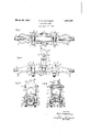
- FIG. 1 of the accompanying drawings is a, top plan view of a clampconstructed in c accordance with my invention, partsy being omitted for 4clearness, l
- Fig.l 2 is a side elevational view'otfthc lstructure shown inl Fig. ,1, with certain por tions broken away,
- the conductor-receiving'member 2 is of a usual channel shapeV having flared ends
- trunnions may be formed, by cast- 'i ingdrop forging, die-pressing sheet'mate-f rial orother operations, by utilizing material that would 'ordinarily constitute a portion of the straight side walls 14 of the channel inember 2,
- the trunnio'nslQV are of substantiallyv hal'tfround channel or f U-shape, -disposed about the lower ends of openirgs15 ⁇ ot subnel; member 2;
- the bolts 5 may be U or J bolts that are secured in position by lock Washers 20 and A I nuts 21.
- the supporting'ror suspension yokelfdis' Y p preferably constructed of half portionsi. ,Y
- thatare joinedvby a bolt25-and include ,cQmyplernentary half-socket portions garldj'deV ⁇ Y *pending legs 27; the latter having free-end bearing portions 28 for disposition,-aboutthetrunnion portions 12 of the channel 2.
- VV11A conductor clamp comprising-lacon,- duotor-re'ceiving channel member Vincluding side Wallsv having openings-laterally therethrough and pivotsupportingelements y of substantially lcliannel-shape ⁇ projectii'izg' laterf ally from said Walls partially'abont saidopenings, said velements being integrally united:v to ⁇ 5o said Wallsand of the materialf displaced y therefrom to provide i said openings;V 2.
- a conductor clamp comprising-acon- Vductor-receiving channel member lh'avino y' Vside-Wallopenings of substantially Y 192s.y Y
Landscapes
- Clamps And Clips (AREA)
Description
March 29, N. A, WAH| BERG CONDUCTOR CLAMP Filed sept. 13, 1928 Patented Mar. 29, 1932 NiLs A; WAHLBERG, or iiiiiarvv;u rENNsYLviiNIAfAssIGNon Vrro wEsTrNGHoUsn ELEC- Y Taio a MANUFACTURINGCOMPANY, n conronA'rroN or PENNSYLVANIA -ooNnucTon CLAMP L applicati@ inea september 13,'1928. serial No, 305,731.1
'clamp itself, an insulator to which theVv suspension element is attached and a main supporting tower or a structure.
AnotherY object of my invention Vis to 'pro` vide a clamp embodying a conducto-rreceiv# ing channel memberl that shall so embody novel integral side trunnion or supporting portions as to provide a rugged and compact structure that conserves material, reduces the number of clamp parts and has other advantages. f
A further object of my invention is to provide a clamp that shall be simple and durable in construction, economical to manufacture and eil'ective in its operation.
It is usual, in supporting high-voltage transmission-line conductors or cables, toprovide clamps having channel members for receiving the conductors.
It has been suggested to support such a channel member bytrunnions projecting laterally from the channel side wallson axes extending through the longitudinal axisl of the conductor for the reception of a pivoted suspension element or yoke.
The latter structure, by reason of the positions of the trunnionuaxes relative too the aXis Vofthe conductor, prevents th-e imposition of certain damaging forces from the conductor and channel member against the suspension element of the clamp and other Vparts Vconnected to the suspension element. l
However, by reason of the peculiar position of the trunnions relative to the side walls of the channel, manufacturing diiiiculties occur in the provision ofthe trunm'ons at thesev positions, it being diiiicult'to drop forge or cast solid cylindrical trunnions onthe relatively thin side walls of the channel members.
In an endeavor to overcome the above-mentioned. objections, it has been proposed to' V,expense of providing `ed trunnions.
` provide .y separately formed means, or means constructed independently of the channel Vmember and secured thereto, for supporting the trunnions. This structure is relatively` complicated and expensive. -4
It is my aim to overcome all oit the'` above mentioned Objections and accordingly, in y practicing my inventinon, I provide a single integral channel member and trunnions-thatV eo y areso formed thereon asto overcome the difiiculty of providing solidv trunnions and-the yindependently-mountf Figure 1 of the accompanying drawings is a, top plan view of a clampconstructed in c accordance with my invention, partsy being omitted for 4clearness, l
device shown in Fig. 1, and` Figi. 4 is a sectional view taken substantial;-
lyalong the line of Fig'. 1 i
I The devicefcomprises, in general, a conductor-receiving or channeljmemberl 2 for supporting a conductor 3, a clamping shoefl 'disposed above the conductor Sfinthechannel 2,
The conductor-receiving'member 2 is of a usual channel shapeV having flared ends,
The exception to the general shape of such for preventing fatigue ,ofv the conductor 3f, l* i members, as usually formed, resides in laterv,
ally proj ecting side trunnion portions 12.
These trunnions may be formed, by cast- 'i ingdrop forging, die-pressing sheet'mate-f rial orother operations, by utilizing material that would 'ordinarily constitute a portion of the straight side walls 14 of the channel inember 2, The trunnio'nslQV are of substantiallyv hal'tfround channel or f U-shape, -disposed about the lower ends of openirgs15` ot subnel; member 2;
Astant-ially U-shape in the sides of the chanj j stantially conforming tothe shape of the conductor 3, flared end portions 18 and seat n' portions 19 for positioning the bolts 5.l
The bolts 5 may be U or J bolts that are secured in position by lock Washers 20 and A I nuts 21.
The supporting'ror suspension yokelfdis' Y p preferably constructed of half portionsi. ,Y
, thatare joinedvby a bolt25-and include ,cQmyplernentary half-socket portions garldj'deV` Y *pending legs 27; the latter having free-end bearing portions 28 for disposition,-aboutthetrunnion portions 12 of the channel 2.
' In operation, since relative movement! off the suspension element '6, and the channel meniber'Q is only throu'glra part'ofa revolu- V tion-away from the position indicatedfin-Fig.
Ahated.
2,'substantia-lly all 'of the Weight of the conl ductor andclamp parts remains at theloWer bearing surfaces rvofthe portions j28-so that complete cylindrical trunnions are not essen# tial.
In'ordin'ary clamp lstructures having'the axesy oflsuch trunnions orsimil'ar members disposed any appreciable distance abovefor below the conductor7 damaging orcesarelimposed against the suspension'element in re- `sponse to vibration or oscillation'ofthe cen-` ductor lorfcable 3.V
In -the structure constituting my invention, since the-axesof the trunnions -121are-'disposed in alignment with each othenor-ona com'inonV axis extending substantially-through the longitudinal central a-Xis ofI theconductor-7.3, these forcesr are substantially elimi- While I'havef-shown and described agpar- "'ti'cnlar Vform of myinvention, vc-hangesgnfiay be 'effected therein Without departing A'from the spirit andscope-thereof, as set-forth in :theappen'ded'claims Y Y 'f -I claimlas my invention: Y Y
VV11A conductor clamp comprising-lacon,- duotor-re'ceiving channel member Vincluding side Wallsv having openings-laterally therethrough and pivotsupportingelements y of substantially lcliannel-shape `projectii'izg' laterf ally from said Walls partially'abont saidopenings, said velements being integrally united:v to `5o said Wallsand of the materialf displaced y therefrom to provide i said openings;V 2. A conductor clamp comprising-acon- Vductor-receiving channel member lh'avino y' Vside-Wallopenings of substantially Y 192s.y Y
Ueshape and pivot=supporting elements of'similar shape projecting laterally to saidW-alls adjacent'to tlieclosed ends of'said openings,
s said laterally projecting` elements being intel grally united to said Walls and of the material displaced therefromto provide said openings.- y Y, v, In testimony whereof, I havehereun-to sub-` scribed niy nanie this 4th day of September, NILsVA. -WAHLBERGB
Priority Applications (1)
| Application Number | Priority Date | Filing Date | Title |
|---|---|---|---|
| US305731A US1851552A (en) | 1928-09-13 | 1928-09-13 | Conductor clamp |
Applications Claiming Priority (1)
| Application Number | Priority Date | Filing Date | Title |
|---|---|---|---|
| US305731A US1851552A (en) | 1928-09-13 | 1928-09-13 | Conductor clamp |
Publications (1)
| Publication Number | Publication Date |
|---|---|
| US1851552A true US1851552A (en) | 1932-03-29 |
Family
ID=23182091
Family Applications (1)
| Application Number | Title | Priority Date | Filing Date |
|---|---|---|---|
| US305731A Expired - Lifetime US1851552A (en) | 1928-09-13 | 1928-09-13 | Conductor clamp |
Country Status (1)
| Country | Link |
|---|---|
| US (1) | US1851552A (en) |
-
1928
- 1928-09-13 US US305731A patent/US1851552A/en not_active Expired - Lifetime
Similar Documents
| Publication | Publication Date | Title |
|---|---|---|
| US3233853A (en) | Aerial cable brackets | |
| US1851552A (en) | Conductor clamp | |
| US1068144A (en) | Switch-rod. | |
| US617062A (en) | Insulating-arm | |
| US1173642A (en) | Equalizer-yoke. | |
| US1815392A (en) | Switch | |
| US1378667A (en) | Cable-clamp | |
| US1799977A (en) | Distributor ring | |
| US1802743A (en) | Transmission-line device | |
| US940309A (en) | Trolley-head. | |
| US2045150A (en) | Transmission line support | |
| US550683A (en) | Trolley-wire crossing | |
| US1756651A (en) | Strain insulator | |
| US456574A (en) | Span-wire insulator | |
| US1871350A (en) | Suspension clamp | |
| US1810053A (en) | Suspension clamp | |
| US1981339A (en) | Aerial mast | |
| US1690392A (en) | Insulator pin | |
| BE367020A (en) | ||
| US2184587A (en) | Supporting arm device | |
| US1511379A (en) | Wire-retaining device | |
| US793651A (en) | Aerial for wireless signaling. | |
| US1883260A (en) | Suspension clamp | |
| US1707479A (en) | Switch | |
| US1374561A (en) | Trolley-hanger |