US1851548A - Charge forming device - Google Patents
Charge forming device Download PDFInfo
- Publication number
- US1851548A US1851548A US307746A US30774628A US1851548A US 1851548 A US1851548 A US 1851548A US 307746 A US307746 A US 307746A US 30774628 A US30774628 A US 30774628A US 1851548 A US1851548 A US 1851548A
- Authority
- US
- United States
- Prior art keywords
- fuel
- air
- valve
- piston
- dash
- Prior art date
- Legal status (The legal status is an assumption and is not a legal conclusion. Google has not performed a legal analysis and makes no representation as to the accuracy of the status listed.)
- Expired - Lifetime
Links
- 239000000446 fuel Substances 0.000 description 53
- 239000000203 mixture Substances 0.000 description 24
- 230000001276 controlling effect Effects 0.000 description 7
- 230000000979 retarding effect Effects 0.000 description 6
- 230000001133 acceleration Effects 0.000 description 4
- 238000005266 casting Methods 0.000 description 3
- 238000002485 combustion reaction Methods 0.000 description 2
- 239000000839 emulsion Substances 0.000 description 2
- 239000007788 liquid Substances 0.000 description 2
- 238000005086 pumping Methods 0.000 description 2
- 241000574671 Acomis Species 0.000 description 1
- 241000027294 Fusi Species 0.000 description 1
- 241000953561 Toia Species 0.000 description 1
- 230000015572 biosynthetic process Effects 0.000 description 1
- 150000001768 cations Chemical class 0.000 description 1
- 238000010276 construction Methods 0.000 description 1
- 230000008878 coupling Effects 0.000 description 1
- 238000010168 coupling process Methods 0.000 description 1
- 238000005859 coupling reaction Methods 0.000 description 1
- 235000003642 hunger Nutrition 0.000 description 1
- 238000004519 manufacturing process Methods 0.000 description 1
- 239000002184 metal Substances 0.000 description 1
- 229920000136 polysorbate Polymers 0.000 description 1
- 230000001105 regulatory effect Effects 0.000 description 1
- 238000009877 rendering Methods 0.000 description 1
- 235000002020 sage Nutrition 0.000 description 1
- 239000007787 solid Substances 0.000 description 1
Images
Classifications
-
- F—MECHANICAL ENGINEERING; LIGHTING; HEATING; WEAPONS; BLASTING
- F02—COMBUSTION ENGINES; HOT-GAS OR COMBUSTION-PRODUCT ENGINE PLANTS
- F02M—SUPPLYING COMBUSTION ENGINES IN GENERAL WITH COMBUSTIBLE MIXTURES OR CONSTITUENTS THEREOF
- F02M21/00—Apparatus for supplying engines with non-liquid fuels, e.g. gaseous fuels stored in liquid form
-
- F—MECHANICAL ENGINEERING; LIGHTING; HEATING; WEAPONS; BLASTING
- F02—COMBUSTION ENGINES; HOT-GAS OR COMBUSTION-PRODUCT ENGINE PLANTS
- F02M—SUPPLYING COMBUSTION ENGINES IN GENERAL WITH COMBUSTIBLE MIXTURES OR CONSTITUENTS THEREOF
- F02M2700/00—Supplying, feeding or preparing air, fuel, fuel air mixtures or auxiliary fluids for a combustion engine; Use of exhaust gas; Compressors for piston engines
- F02M2700/13—Special devices for making an explosive mixture; Fuel pumps
Definitions
- This invention relates to chargeV forming devices for internal combustion engines and more particularly to the type'of charge forniing device which comprises a plurality of primary-fuel miningchambers, one for each inthe engine spectively with a plurality of secondary ⁇ fuel mixing chanibei'slocated adjacent the engine intake ports, and receiving fuel airrnixture from pipes connected withV the primarycarburetors, and receiving air when require through branches of an air manifold havingV a single air inlettor supplying Vain-to all the secondary mixing chambers, the quantity of mixture iiowing through bui-eters heine: controlled glo main air throttle. ⁇ I fuel to all of saidpriprimarily by a sinmary carburetors. o l .i
- the device disclosed infthe above appliv cationvarious means are provided for regulating the proportions ofiue and air in the mixture under different operating conditions, so as to provide portions to secure properfoperation of the en-V ainixture of the desired progine vunderall conditions of speedfand load.
- these mixtureproportioning devices is a dash pot which dainps theopening movenient ofthe main air valve on opening of the throttle and comprises a cylinder having a check val-ve inthe bottom designedto open as the valve closesto permit unretarded closing Imovement of said valve; and which has a f:liiel ⁇ delivery conduit connected thereto 'through which Juel is forced to the-'mixture passages on opening ofthe throttle to enrich p the mixture Jfor acceleration.
- the present invention is inv the nature ofV an improvement to above application and the primaryobject of the invention is to provide improvedmeans for controlling; the mixture proportions ⁇ on opening of the throttle, which'is siniple'in construction, positive in its action and relatively cheap to manufacture.v Morefspecilically, an
- objects y which comprises a 'cylinderfhaving asolidV bottom which is not provided with-iaicheck l capacity equalyto.
- Thislfuel isavailable to run baclrlint'o the dash pot cylinderon anyinovementoithe Q o To, ,Y f vthe check v 'alveinl th'efbottom of the' cylinder unnecessary" toif ⁇ p'er 'rr1 ⁇ it unretarded closing 'A i vair valve toward closed position, rendering movement :off the valvelf stitutes va part of the through whichV
- the well also conj valve, but which instead cominunicatesfwith i fuel ⁇ from the main ufel fuelfdelivery conduit, fuel isfforced fromth'e dash pot cylinder fand said ⁇ well is providedfwith v' a ⁇ restricted fuel conduitileadin'g torthefii'ii'xture passages and' a small orifice connecting withthe fuellbowl"forgfillingithe welly so that the well is'normally illed at the beginning of any opening-oi
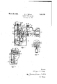
- Figui is-'avertical'loiigitudinal section A througha charge forming device in which "the resentlinvention embodied; o *1 FigsfQandBare sections ontlielines and' 3-3 respectively of f Fig; L
- the device disclose d comprises manifold V10 having threeoutletl branched*y "the middle branch-12 being shown herein.
- Each of these branches communicateswith one ofthe'intake port-s la of amulti-cyliiider engine.”
- These ou let branches are each provded withanfattaching ⁇ ange 16 for securing the manifo the main carburetor unit is ing 2() having an ⁇ through--arconduit p Y .flowrnfgfuelito thebowl is controlled by a ld to the engine block in the usual manner.
- Adjacent the inlet of the manifold isprovided a flange 18 to which.
- the carburetor unit comprises a main housattaching flange.22 adapted flange 18 by screws 24.
- Fuel f is conducted' from :a maingsource, off-supply to the fuel 'bowl not shown' herein and the float 36,- operating .inv theY usualmanner to :maintain l a substantially constantk VVlevel @of -fuel therein.
- a single throttle valve 64 whicliexten'ds across all the primary mixture passages, con- .trols-the flow therethrough and is provided with grooves 66 which register furerassges- Y means fully disclosedin the above copending Vapplicati-on-and which forms no part of 'the present invention.
- the -mixture passage connects lfixed in the manifoldv branch Weys the primary ⁇ 'mixture ,to
- Thisthrottle is operated by 12, which con- 'middle primary -mixing chamber in that branchof themani-- fold Y 1- y"Substantially all the air entering the carburetor flowsthrougli the 'air horn 28controlledby a mainair-valve-TO, normally held spring 74received.
- the valve 70 admits Aber 88ffrom which air flows to the primary mixture passages throughan orifice 90 in the ⁇ floor of the air chamber and tothe' secondary Amixing chambers through a passage 92, which .connects with the inletof themanifoldvlO.
- a manually Voperable throttle 94 anda suction ⁇ Voperatedvalve .'96 control the owfof air throughy passage 92 and the operating-connec- .tions for saidvalves are .fullydisclosed in v,the above mentioned application.
- vA 'dash pot is provided sult and to prevent fluttering of the valve comprising a cylinder forming casting 30 and 'alvestem182b vmeans' of a flanged 'coupling memberfl'04 pinned to saidfstem, the piston suppliedy to the en-1 1 gine. .
- the opening ofthe valve must be res to isome extent, however, lto preventv to lean the inixture to;accomplislithis re-V part of the .a piston 102 secured to ther isc draw fuel fiom abovethepistonthroughbyf Y,ce
- dash pot operates sub ⁇ Downward movemen of the piston forces fuel from'the cylinder100, first through Vthe* passage being determined bythe rate'of flow'fromlthe cylinder. ⁇
- dash pots heretofore employed acheck valve has been provided either. in the piston or cylinder to prevent the formation of a vacuum below the pistonwhen the latter starts its return movement.
- the check valve has been eliminated,but the air valve is vpermittedto ⁇ close substantially without retardation. Let it be assumed that the valve is open and the piston is below theV upper end of -byLpass 110.
- the abovedescribed dash ypot also constitutes arfuel pump to supply additional fuel cate with three passages 114 and 'then 110, the speed of the piston
- the by-pass thew Vpiston without reducing the eiciency of v not have been ⁇ possible to the mixture ypassages on opening' movementsof the throttle to enrich the mixture .for
- One or more-passages126 admit air'tothel l channel 121, which forms an emulsion ⁇ with the fuel in said channel, this emulsion being so w forced through'passages122 and 12a on dowiiward movements of the Apiston 102.
- Air isi-admitted to channelf121to the high mixing chamber suction acting to draw fuel from cylinder100 independently of the pumping action of the pistonl02.V 1A high ⁇ suction ,is ⁇ maintained in the mixing chamberslunder all conditions of. operation i and unless thefuelfdelivery passage werel this suction would operate to lift fuel from' tliecylinder 102 at all times,while it is Vprevent desirable to supply thisadditional fuelonly v on openin of the throttle. admit sufiicient air to the channel Jerusalem the suction eifective'on'the passage .121 to re It is. desirableto so it can lift fuelrto a-pointslightlybelow t the channel 121,but no higher. f. l Thereservoir 112,is normally fullof fuel 102v starts downwardly.
- a secondary mixing chamber is associated with each outlet branch ofthe manifold, one
- Each of these mixing chambers compris'esra Venturi tubelSO clamped between the inanifold and the engine block,
- Vhilethe form of embodiment of the presenty invention as herein disclosed, constitutes a preferred ⁇ form, it is to be understoodthat other forms might be WVhat is claimed is as follo-Ws:
- a charge forming device comprising a msans-supplyingfuel and tardingthe opening ofV the air.v valve, a bypassfconnected at? two vertically spaced pointswiththe dash pot cylinder adapted to be rendered effective 4.during opening; of
- A'cliarge forming device -comprising'a means supplying fuel and air thereto, a suction operated air Vvalve controlling' the admission of'air, a. dash pot retarding the openingof the ⁇ air valve; a bypass connected at tivo vertically spaced cylinder adapted to be rendered effective during opening of the neet-ing the auxiliary means' 'being renderedk inet, -A charge forming device comprisinga mixture passage, means supplying fuel and air thereto, a suction operated'air valve controlling the admission of air, ad'ashpot/jretardingthe opening of-'the air valve,a bypass connected at ⁇ tvo Vvertically spaced points with the dash pot cylinder, one-end of which is coverediby the pistonl ⁇ in closed position ofthe valve and is adapted tobe un'-l covered as the valveopens, van auxiliary rese'rvo'irand means connecting 'the auxiliary yreservi'iir with the dash
- the dash pot cylinder intowhich fuel is Vforced by thel dash potV an auxiliary reservoir means coni reservoir
- the dash rissa-64s e combustion enginesv comprising ia fuel reservoir,- a. mixture passage, means :suppl-yingy fuel and.-v airtheretoy va suction operated air valvejcontrolling admission of air
- V'a dash potV retarding v the opening,v of the air valve" and supplying additional fuel to the mixing chamber for acceleration on ⁇ openingy of the pot retarding the opening of the air'valve relatively
- charge forming device for multi-cylinder engines comprising a fuel reservoir, a
Landscapes
- Engineering & Computer Science (AREA)
- Chemical & Material Sciences (AREA)
- Combustion & Propulsion (AREA)
- Mechanical Engineering (AREA)
- General Engineering & Computer Science (AREA)
- Control Of The Air-Fuel Ratio Of Carburetors (AREA)
Description
March 29, 1932. H. TEETER l 1,851,548
CHARGE F'ORMING DEV-ICE Filed Sept. 22, 1928 Y d/gmwmmm s 1 fof. no
take port ot yvoir supplies liquid this typev is disclosed in PatentedMar. 29,1932
narran STAT-Es FATENTQFFI'C 'fistsisl wiLiionn H. METER," or niiironfoiiio,
iissienoit, BY ivinsivn'ifi'ssieivifinnfrsgro nnLoo rnonucfrs coRPonA'iioiv, or' DAYToN, oHio, A o oiarpna'rion onnntawnin i CHARGE ronmiivejnnvion Appiioation fuori september 22, 192s; serial Naeomi'e.
' This invention relates to chargeV forming devices for internal combustion engines and more particularly to the type'of charge forniing device which comprises a plurality of primary-fuel miningchambers, one for each inthe engine spectively with a plurality of secondary `fuel mixing chanibei'slocated adjacent the engine intake ports, and receiving fuel airrnixture from pipes connected withV the primarycarburetors, and receiving air when require through branches of an air manifold havingV a single air inlettor supplying Vain-to all the secondary mixing chambers, the quantity of mixture iiowing through bui-eters heine: controlled glo main air throttle.` I fuel to all of saidpriprimarily by a sinmary carburetors. o l .i
lfinexample of a charge forming device of the copendinp;4 appli-y cation of Aseltine, Carl H.-Kin`dl,
Fred E.
ln the device disclosed infthe above appliv cationvarious means are provided for regulating the proportions ofiue and air in the mixture under different operating conditions, so as to provide portions to secure properfoperation of the en-V ainixture of the desired progine vunderall conditions of speedfand load. Among; these mixtureproportioning devices is a dash pot which dainps theopening movenient ofthe main air valve on opening of the throttle and comprises a cylinder having a check val-ve inthe bottom designedto open as the valve closesto permit unretarded closing Imovement of said valve; and which has a f:liiel `delivery conduit connected thereto 'through which Juel is forced to the-'mixture passages on opening ofthe throttle to enrich p the mixture Jfor acceleration.
The present invention is inv the nature ofV an improvement to above application and the primaryobject of the invention is to provide improvedmeans for controlling; the mixture proportions `on opening of the throttle, which'is siniple'in construction, positive in its action and relatively cheap to manufacture.v Morefspecilically, an
`means 'for lcontrolling the -airvalve and an improvedform'ofpump for alffuel to-thefinixture passagesV to enrich the mixture Jfor acceleration.`
Supplying :addition and cooperating .re-
leare' 4accomplished by the provision of'. la `dash Vpot controlling the inotionlof the fair valve,44
a well supplied with bowl, and` having av Vthe 'secondary cai'-` ton during `its -moveme A common fuel' reser-` sonoi No. 288,683,
the devicedisclosed in the provide improved movements y of- 4 the obj ect of the invention to According to this. invention these: objects ywhich comprises a 'cylinderfhaving asolidV bottom which is not provided with-iaicheck l capacity equalyto. the j amount'of fuel displaced the dash pot pis- Y nt 4Vfrom normal position to a' position where the upper 'end of a by? pass in the |`wall of 4said cylinder 'is uncovered. Thislfuel isavailable to run baclrlint'o the dash pot cylinderon anyinovementoithe Q o To, ,Y f vthe check v 'alveinl th'efbottom of the' cylinder unnecessary" toif`p'er 'rr1`it unretarded closing 'A i vair valve toward closed position, rendering movement :off the valvelf stitutes va part of the through whichV The well also conj valve, but which instead cominunicatesfwith i fuel `from the main ufel fuelfdelivery conduit, fuel isfforced fromth'e dash pot cylinder fand said `well is providedfwith v' a `restricted fuel conduitileadin'g torthefii'ii'xture passages and' a small orifice connecting withthe fuellbowl"forgfillingithe welly so that the well is'normally illed at the beginning of any opening-oi th'evalve` f Further objects andl advantagesof the present invention will be apparent from thefollowing description, reference beinghad to the accompanying drawings, wherein apreferred form of' embodiment of the presentinvention is clearly shown.` f
vIn the drawings:
Figui is-'avertical'loiigitudinal section A througha charge forming device in which "the resentlinvention embodied; o *1 FigsfQandBare sections ontlielines and' 3-3 respectively of f Fig; L
The device disclose d comprises manifold V10 having threeoutletl branched*y "the middle branch-12 being shown herein.
Each of these branches communicateswith one ofthe'intake port-s la of amulti-cyliiider engine." These ou let branches are each provded withanfattaching `ange 16 for securing the manifo the main carburetor unit is ing 2() having an `through--arconduit p Y .flowrnfgfuelito thebowl is controlled by a ld to the engine block in the usual manner. Adjacent the inlet of the manifoldisprovided a flange 18 to which.
adapted to be at-A tached as shown in Fig. 1. i
The carburetor unit comprisesa main housattaching flange.22 adapted flange 18 by screws 24. An
to be secured to y is secured in `position to regair inlet horn28 KYister with yanopening inthe-upper Wall'of housingj20, in 4any suitable "way. Y A casting 30, having certain dash pot chambers and fuel passages formed therein, is securedby screws to the lower Wall `.of housing 2Q,.and a sheet metal fuel bowl 3 2 is held tight against Van.anrrl'1lar, shoulder 34:0nthe-hfousiii-g 20fby Riny- ;sui-tablefmeans. v
Fuel f is conducted' from :a maingsource, off-supply to the fuel 'bowl not shown' herein and the float 36,- operating .inv theY usualmanner to :maintain l a substantially constantk VVlevel @of -fuel therein.
Y .Fuel vflows ,from bowl 32.,toia Aplurality of primary fuel-nozzles 38,-fone'of whidifi-s-located in each of the prim-ary mixing chambers 40, theconstruction of which .is briefly described hereinafter. .tweenthefuelbowl and' `a. vertical fuel Vpassage- `its upper end vwith fa horizontal fuelcanal44 thelnozzles comprises communicating at which" connects lwith each of the nozzles v,38 through v'orifices ,467. Fuel yis admitted vfrom the fuel;l yEloowl to passage 42.v aatV all. L speeds through Aa `fixed metering iorice 48 andgat high* speeds` additional .fuel/is admitted throughijanlorificeOcontrolled'by a valve `52 v in the manner setV forth-in thegahove mentionedapplication.
.the aboveV described fuel .passages l and noz Y i zlefsBS- to the -mixing chambersaby thefsuction therein. Closing movementsof -the throttle vnausea reduction in mixing chamber suction, which might permit thel fuel column;V to drop sufficiently .to cause a .temporary fuel starving oft-heengine unlessmeans wereprovided to prevent it-. For this purposefaicheck valve V54 is prov'ded in 'anenlarged cliainberj at the junctionof channels'42and44, and on re-- duction of mixingchamberY suction `seatsV on the bottomfof its chamber, preventing downward flow of the fuel. I. g
f nach primari/ fusi nozzle is piovide'iwah The j' fuel vcon-duit if vEach nozzley is provided with a restricted-v The primary mix# ture passages 40 are'parallel to each other fuel metering orifice 63.
and close together-as indicated in Fig. 2, and
Awhen the carburetor is attached' to the manifold,tl'iese passages register withv conduits `which 4convey thel primary mixture to the Vsecondarymixing chambers, as fully disclosed Vin the' copending application referred to.
A single throttle valve 64, whicliexten'ds across all the primary mixture passages, con- .trols-the flow therethrough and is provided with grooves 66 which register furerassges- Y means fully disclosedin the above copending Vapplicati-on-and which forms no part of 'the present invention. 1 The -mixture passage; connects lfixed in the manifoldv branch Weys the primary `'mixture ,to
with a Vtube 68,
the secondary with said'mix Thisthrottle is operated by 12, which con- 'middle primary -mixing chamber in that branchof themani-- fold Y 1- y"Substantially all the air entering the carburetor flowsthrougli the 'air horn 28controlledby a mainair-valve-TO, normally held spring 74received. be-
76 projecting Y against a lseat, 72 byza tween the vvalve .and a liange rom a sleeve 78slidablymountedion-a sta-- ,tionary 'guide sleeve; 80, lfixedV `20 and yserving as a guidesleeve for thestem 82'to which theair valve is secured.-
1 When it isadesired to choke the carburetor `to jstartthe engine,fthe flange is adapted to be lifted, by means not shown herein, until the f-upperfend of 4sleeve, A78 engages the valve to hold it against itsseat. Suiicient air to carry Jthe startingV fuely from the nozzles to the inv-i take-ports is admittedthrough'anelongated 'slot 84 formedin a platei861securedtoftheV Yhousing 20,2 as shown in Fig. 1. The valve 70 admits Aber 88ffrom which air flows to the primary mixture passages throughan orifice 90 in the `floor of the air chamber and tothe' secondary Amixing chambers through a passage 92, which .connects with the inletof themanifoldvlO. A manually Voperable throttle 94 anda suction` Voperatedvalve .'96 control the owfof air throughy passage 92 and the operating-connec- .tions for saidvalves are .fullydisclosed in v,the above mentioned application.
air to a main air chamin the housing floo. l
AOnopening of either .throttle 64 Vor 94 the suction-in the air chamberSS isincreasedand lthe air valve is opened against the tensioiiof. i
its's'pring to admit additional air and increase the quantity of mixture ltarded. admissionof sufficient air vA 'dash pot is provided sult and to prevent fluttering of the valve comprising a cylinder forming casting 30 and 'alvestem182b vmeans' of a flanged 'coupling memberfl'04 pinned to saidfstem, the piston suppliedy to the en-1 1 gine. .The opening ofthe valve must be res to isome extent, however, lto preventv to lean the inixture to;accomplislithis re-V part of the .a piston 102 secured to ther isc draw fuel fiom abovethepistonthroughbyf Y,ce
'prevent further upward moveme `stantially as follows;
L. through by-pass i Ying of the valve being clamped between lthe iangeoniisaid `coi'ipling member and a nut f 106 i threaded thereon.4 The lower end of-thedash pot `cylinder is closed by aV solid plug 108 screwed into the` cylinder, anda by-pass 1110, both ends of which communicate with therinterior of the dash pot cylinder, is formed in the wall thereof. The piston 102 closes the upper end of the by-pass when the air .valve is closed. As Athe valve opens Vthe piston uncovers the end of the passage 110, permitting passage of fuel from below the piston through the byass in order to partially relieve the dash pot at high speed and permit less retarded opening of the air valve. Y Y
Y On the closing'of the valve, fuelmust be admitted to the cylinder below the piston 102,
or the'upward movement of the piston would l create a vacuum below said piston at the beginning of such movement which would tand `the To admitfuelto 102, a well 112 is air ,valve would not close.
below piston 114 with the cylinder 100. This well has a capacityat least; equal to the amount of fuel displaced .by the piston 102 beforefsaid piston uncovers the upper end of by-pass 110. A small-hole 116ipermits f uel from'the float bowl to flow into tliewell 112.
i The above described dash pot operates sub` Downward movemen of the piston forces fuel from'the cylinder100, first through Vthe* passage being determined bythe rate'of flow'fromlthe cylinder.` In dash pots heretofore employed, acheck valve has been provided either. in the piston or cylinder to prevent the formation of a vacuum below the pistonwhen the latter starts its return movement. In the dash pot clisclosed,.the check valve has been eliminated,but the air valve is vpermittedto` close substantially without retardation. Let it be assumed that the valve is open and the piston is below theV upper end of -byLpass 110. On a closinginovementof thethrottle suction in vthe chamber 88 is reduced and spriiigft moves the valve towardY closedpositiointhe piston 102moving upwardlyyand creating'a vacuum below the piston. This vacuum wil pass until the upper end of thebyfpass' is covered by the piston, at which point the clos- `would cease if the well 112 were not provide-d. is covered the passage llllis uncovered anc fuel Vflows from the well112 into'cylinder 100, satisfying thevacuum' formed therein as air valve' continues its closing movement. The orifice 116 permits the filling-.of thewfell with fuel after the `fuel vtherein has been drawn out as described. i
The abovedescribed dash ypot also constitutes arfuel pump to supply additional fuel cate with three passages 114 and 'then 110, the speed of the piston However, as :the by-pass thew Vpiston without reducing the eiciency of v not have been `possible to the mixture ypassages on opening' movementsof the throttle to enrich the mixture .for
a part of the the dashV 4pot.
A passage channel'121 bored in casting 30 and connect- 122 4which communiy 12a in the main housing 20, each of which communicates with one of the `mixture passages fthasshowii in Fig...
ing y with. three passages 1.. One or more-passages126 admit air'tothel l channel 121, which forms an emulsion `with the fuel in said channel, this emulsion being so w forced through'passages122 and 12a on dowiiward movements of the Apiston 102.
Air isi-admitted to channelf121to the high mixing chamber suction acting to draw fuel from cylinder100 independently of the pumping action of the pistonl02.V 1A high `suction ,is `maintained in the mixing chamberslunder all conditions of. operation i and unless thefuelfdelivery passage werel this suction would operate to lift fuel from' tliecylinder 102 at all times,while it is Vprevent desirable to supply thisadditional fuelonly v on openin of the throttle. admit sufiicient air to the channel duce the suction eifective'on'the passage .121 to re It is. desirableto so it can lift fuelrto a-pointslightlybelow t the channel 121,but no higher. f. l Thereservoir 112,is normally fullof fuel 102v starts downwardly.
whenever theV piston vDowiiward ymovementof the`piston therefore Y forces fuel through the restricted conduit 120.," which retards-suchv movement.
114, however, `is large enough to permit relatively free. return movement of the piston, the fuel inthe auxiliary reservoir running into' The passage 1" los the dash pot cylinder to satisfy the vacuum g j createdbyreturn of the' piston andthe pas-v sage 120 servingas a vent.. Y A secondary mixing chamberis associated with each outlet branch ofthe manifold, one
iiu Y of such mixing chambers being shown herein.
Each of these mixing chambers compris'esra Venturi tubelSO clamped between the inanifold and the engine block,
theoutlet ofthe primary `mixture conduit associated therewith terminate'sfatzthe point ofv TheseV Venturi present inven-l fully set forth greatest suctionv thereinii` K tubes 'constitute no part'of the tion, but function in a manner in the y above mentioned application.
v Itwill be clear that by theprovisionofthev l well 1121in the delivery conduit from the dash pot cylinder to the mixture passages, 4theV ape` plicant has accomplished the eliminationgof the check valve formerly used in the dash pot to perinit return movement of the dash pot ump, which would if the outlet passage 114:y communicateddiand positioned so the * means of which thel well fills after an *u1V mixture passage,
- arr thereto, a suction operated air valvecon- Within the scope ofthe Ward' movement ofthe pistoni, is'sof small? comparison to Vthe delivery passage 120' that it has no appreciable elfect'on the pumping `action ofthe dash pot. j
Vhilethe form of embodiment of the presenty invention as herein disclosed, constitutes a preferred `form, it is to be understoodthat other forms might be WVhat is claimed is as follo-Ws:
l: Acharge forming device Vcomprising'a means supplying fuel and trolling tlieadmission of air, a dash pot retarding the opening of the: airV valve, afbyypass connected at 4two verticallyV spaced o points With the Adash l ofthe dash pot, and an auxiliary reservoir communicating with the das-h pot cylinder beloivithenormal posi- ,ing the retarding effect tion ofthe dash pot piston into yvvliich'liquid pot cylinder, said y 'effective as the by-passfis rendered effective.
is forced by vmixture passage', Vair thereto, as uction operated air valve con-` trolling the admission of ai`r,a dash pot remixture passage,
y points Withthe dash Vpot air valve,
is uncovered.
tlie dashpot piston on vopening of the 'air i'falve; Y 1 2. A charge forming device comprising a msans-supplyingfuel and tardingthe opening ofV the air.v valve, a bypassfconnected at? two vertically spaced pointswiththe dash pot cylinder adapted to be rendered effective 4.during opening; of
the air valve, Vand an' auxiliaryjreservoir. communicating `'with piston before the by-pass becomes effective;
V3. A'cliarge forming device -comprising'a means supplying fuel and air thereto, a suction operated air Vvalve controlling' the admission of'air, a. dash pot retarding the openingof the {air valve; a bypass connected at tivo vertically spaced cylinder adapted to be rendered effective during opening of the neet-ing the auxiliary means' 'being renderedk inet, -A charge forming device comprisinga mixture passage, means supplying fuel and air thereto, a suction operated'air valve controlling the admission of air, ad'ashpot/jretardingthe opening of-'the air valve,a bypass connected at` tvo Vvertically spaced points with the dash pot cylinder, one-end of which is coverediby the pistonl `in closed position ofthe valve and is adapted tobe un'-l covered as the valveopens, van auxiliary rese'rvo'irand means connecting 'the auxiliary yreservi'iir with the dash poty cylindervvhen the valve is closed, said' connecting means be'- V ing adapted to be covered by said piston durin@r opening of the kvalve as the by-pass 5. A charge vforming device-for internal adopted, allv coming claims which follow.
pot cylinder for vary- 4mixture passage,
the dash pot cylinder intowhich fuel is Vforced by thel dash potV an auxiliary reservoir, means coni reservoir Withthe dash rissa-64s e combustion enginesv comprising ia fuel reservoir,- a. mixture passage, means :suppl-yingy fuel and.-v airtheretoy va suction operated air valvejcontrolling admission of air, V'a dash potV retarding v the opening,v of the air valve" and supplying additional fuel to the mixing chamber for acceleration on` openingy of the pot retarding the opening of the air'valve relatively I a suction operated airvalve controlling admission of air, a 'dash and supplying additional fuel to tl'iemixing chamber 'for acceleration '-on openingfo'fthe throttle, anV auxiliary reservoir forming a g 1 part of the :-fuel delivery conduit having? a relatively 'large passage communicating with 'the' dash' pot cylinder-anda relatively small passage communicating Y With the y fuel reservoiinu` "7, A charge forming devieecomprising a :tardin'g the openingl of the air'valve, a bypass connected attwomvertically `spaced points With the dash. pot' cylinder adapted to berendered effective during opening Vof the airfvalve, andan municatingvviththe dash pot cylinder into which fuel is forced by thel dash potV piston before the by pass 1bec'oinesheifective, said vauxiliary 'reservoir havinga` capacity as fueldisplacedby the great as the volume of piston-before the by-pass is rendered effective. s 8. charge forming device for multi-cylinder engines comprising a fuel reservoir, a
plurality of-'mixture passages eachof Whichr isadapted tosupply fuel air mixture to a' separate'intale'pora-,means lfor supplying fuel and air to saidfmixture passages, a suction operated valve controlling admissionof air :toall said passages, a dash pot for retarding the opening of th'eflair valve and supplying additional fuel toall `ofsaid mixture passages on openingl movement of the throttle, an auxiliary reservoir fhavingrelatively lfree communication; with the dash pot, and'ia restricted delivery-'conduit 'extending 'from the reservoir to all said mixture passages. A f
In testimonywhereof-.Iuhereto affix my signature. Y y f,
n vTILFORD H, TEETER. 'p
means s iuppl'y'ingy fuel andk airthereto, a vsuction operated air vvalve 'controlling the admissionof air, dashpot re-Y auxiliaryV reservoir Acomi'
Priority Applications (1)
| Application Number | Priority Date | Filing Date | Title |
|---|---|---|---|
| US307746A US1851548A (en) | 1928-09-22 | 1928-09-22 | Charge forming device |
Applications Claiming Priority (1)
| Application Number | Priority Date | Filing Date | Title |
|---|---|---|---|
| US307746A US1851548A (en) | 1928-09-22 | 1928-09-22 | Charge forming device |
Publications (1)
| Publication Number | Publication Date |
|---|---|
| US1851548A true US1851548A (en) | 1932-03-29 |
Family
ID=23191015
Family Applications (1)
| Application Number | Title | Priority Date | Filing Date |
|---|---|---|---|
| US307746A Expired - Lifetime US1851548A (en) | 1928-09-22 | 1928-09-22 | Charge forming device |
Country Status (1)
| Country | Link |
|---|---|
| US (1) | US1851548A (en) |
-
1928
- 1928-09-22 US US307746A patent/US1851548A/en not_active Expired - Lifetime
Similar Documents
| Publication | Publication Date | Title |
|---|---|---|
| US1799397A (en) | Internal-combustion engine | |
| US1851548A (en) | Charge forming device | |
| US2346711A (en) | Carburetor | |
| US2207456A (en) | Carburetor structure | |
| US2957683A (en) | Carburetor nozzle | |
| US1904634A (en) | Charge forming device | |
| US1793554A (en) | Apparatus for control of combustion in internal-combustion engines | |
| US1328142A (en) | Fuel-supply mechanism for internal-combustion engines | |
| US1911135A (en) | Charge forming device | |
| US2038157A (en) | Charge forming device | |
| US1825381A (en) | Multiple carburetor charge forming device | |
| US1844738A (en) | Charge forming device | |
| US1798388A (en) | Carburetor | |
| US1960993A (en) | Charge forming device | |
| US2047899A (en) | Charge forming device | |
| US1913144A (en) | Charge forming device | |
| US1797165A (en) | Carburetor | |
| US1884962A (en) | Charge forming device | |
| US1289006A (en) | Combined carbureter and transfer-port. | |
| US1935801A (en) | Charge forming device | |
| US1624604A (en) | Carburetor | |
| US2155104A (en) | Charge forming device | |
| US1782333A (en) | Charge-forming device for internal-combustion engines | |
| US1913741A (en) | Charge forming device | |
| US1943909A (en) | Charge forming device |