US1851534A - Apparatus for handling materials - Google Patents
Apparatus for handling materials Download PDFInfo
- Publication number
- US1851534A US1851534A US238506A US23850627A US1851534A US 1851534 A US1851534 A US 1851534A US 238506 A US238506 A US 238506A US 23850627 A US23850627 A US 23850627A US 1851534 A US1851534 A US 1851534A
- Authority
- US
- United States
- Prior art keywords
- trays
- carrier
- members
- connecting member
- edge
- Prior art date
- Legal status (The legal status is an assumption and is not a legal conclusion. Google has not performed a legal analysis and makes no representation as to the accuracy of the status listed.)
- Expired - Lifetime
Links
Images


Classifications
-
- A—HUMAN NECESSITIES
- A21—BAKING; EDIBLE DOUGHS
- A21B—BAKERS' OVENS; MACHINES OR EQUIPMENT FOR BAKING
- A21B3/00—Parts or accessories of ovens
- A21B3/07—Charging or discharging ovens
-
- B—PERFORMING OPERATIONS; TRANSPORTING
- B65—CONVEYING; PACKING; STORING; HANDLING THIN OR FILAMENTARY MATERIAL
- B65G—TRANSPORT OR STORAGE DEVICES, e.g. CONVEYORS FOR LOADING OR TIPPING, SHOP CONVEYOR SYSTEMS OR PNEUMATIC TUBE CONVEYORS
- B65G47/00—Article or material-handling devices associated with conveyors; Methods employing such devices
- B65G47/22—Devices influencing the relative position or the attitude of articles during transit by conveyors
Definitions
- Apparatus 1 embodying the invention. in-' volves thecombinatjion. of fixed, overhanging, superimposed, and structurally independent treatingmembers with movable overhanging, super-imposed, and unconnected carrying; elements.- which, in their travel, intermeshwith the treating members so as to bring the material on each carrying element in close proximity: to one of the treating members.
- A-specific and important object of the presentiinvention is to secure such intermeshing of-icarrying elements and treatingmembers inahandling, apparatus having collapsible carriers, of the type shown and claimed in the co-pending application of David Baker, Serial-No; 150,443, filed November 24, 1926.
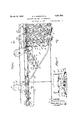
- Fig. l- is a side elevation of part of a complete handling and treating apparatus showing the loading station, a part of the treatment space, andthe means for moving carriers-irom the loading station tothe treat--' ment space;
- Fig. 2 is a transverse section on the line 2.*2.0,f Fig.- 1;
- Fig. 3' is an enlarged transverse section takenon theline 33 of Fig. 1, and showing one of the carriers in the treatment space with; its carrying element intermeshed with the treating members; V V
- Fig. 4 is awplan view of the carriershown Fig. 5 shows one of the carriers in the treatment space in central longitudinal section;
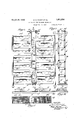
- Fig. 6 is asideelevation of a-carrier at the loading" station, omitting the tracks which supportjthe-carrier;
- Fig. 7 is a plan viewof'a carrier at the load-1 ingstation, omittingthe loading deviceand other partsabove the carrier; p 1
- Fig. Sis a. view similar to Fig.3"showing a modified apparatus;. f c
- the apparatus illustratedg in Figs. 1 to, 7 includes a large number of collapsible. car
- the fixed supports T1 carrying,projectingor overhanging treatment. members T2 7 which are entirely unconnected except for theattachment oftheir outerends; to the supports T1.
- the treatment memberseTZare heating members and; each consists of a gas pipe ha ving on itseu'pper surface"a plurai ity ofgas burners T3.
- theJfiX-ed supports T1 are-alg pipes, servgw PP'Wgas-to the members T2 aswellasto supportthem.
- Each carrier has a rearconn'ectin-g member llwhich may-'be 'made in one'piece,
- each tray is similarly hinged to the front connecting member 14 by means of two tabs 23 near the middle of its front lower edge and tabs 17 on the bars 15.
- the distance between the adjacent hinge pivots of each connecting member isequal to the length of one of the trays 21, so that the trays may be brought into edge-to-edge relation in a common plane by bringing the front and rear connecting members as close together as possible, as shown at the left in Fig. 1 and in Figs. 6 and 7.
- the rear connecting member 11 lies directly over and parallel to the trays 21, while the front connecting member 14: lies directly under the trays and is also parallel to them;
- the traysv 21 may bebrought into various superimposed relations, including a relation in which they lie one directly under another.
- the connecting members and middle portions of the trays form a collapsible parallelogram frame so that the trays are held parallel in all positions thereof.
- fittings 24 Secured to the sides of the uppermost tray 21a of-each carrier are fittings 24 carrying two pairs ofwheels 25, 26 of different gauges,
- the distance between the two tracks and the treatment space is substantially equal to the lengths of the connecting members 11 and 1 1, but it may be made less than this when the size ofthe treatment members T2 permits, as hereinafter eX- plained.
- the tracks 30 and 31. diverge, as clearly shown in Fig. 1. The result is that the trays of each carrier are located edge to edge; in a common horizontal plane as the carrier passes the loading station L, and are horizontal and superimposed when the carrier is in the treatment space.
- the movement of the carriers alongthe tracks is preferably automatic, and may be 'tomatic loading device at the loading'station. The nature of this device necessarily depends upon the nature of the material to be treated.
- the loading apparatus may include a chute L1, rollers L2 at the bottom of the chute, and scrapers L3.
- the middle portions of the trays, which are between the front and rear connecting members 11,14 are not used, and the rollers L2 and scrapers'L3 are positioned to direct the material only into the two overhanging portions 21 of each tray 20, as clearly shown in Fig. 2.
- each tray is preferably provided with partitions 200.
- the thin layerof material which is sprea upon the carrying element 20 at the loading station is broken up into short sections as the carrier moves from the loading station to the treatment space, and these section's'are intermeshed with the treating members T2 so that "each of them is subjected to direct he'attreatment by the treating members over which it passes.
- each carrier10 has a central collapsibleparallelogram frame which includes a rear connecting member 11', consisting of two bars 12 connected by hearing sleeves 16', in which are journalled bearing rods 22 connecting brackets 36 to which the inner sides of overhanging trays 20 are secured; and a front connecting member 14 having bars 15 and bearing sleeves 17 for bearing rods 23 which also connect the brackets 36.
- this parallelogram frame retains all the trays 20 parallel to one another, and permits those at each side of the carrier to be placed either in edge-to-edge relation as shown in Fig. 10 or in superimposed relation as shown in Figs. 8 and 9.
- each treating member T2 shown in Fig. 8 are arranged to direct forcible sprays of liquid directly against the thin layers of material on the carrying elements 20.
- each treating member is provided along its lower side with spray nozzles T3; and to permit the discharge of the liquid, the carrying elements 20 may be provided with foraminous bottoms 37, as shown in Figs. 8 and 11.
- a plurality of carriers such as the carrier 10 shown in Figs. 8 to 11, may be mounted for movement along tracks arranged in the same manner as the tracks 30, 31 shown in Fig. 1, except, of course, that each track is of a much narrower gauge.
- the operation is, therefore, the same as that of the first modification, except for the difference in the treatment applied to the material.
- the apparatus may be used for any other types 'of treatment by merely modifying the treating members to adapt them to effect the particular treatment desired. It should be clearly under-v parallelogram frame, and individual carrying elements projecting laterally from said frame, unconnected at their outer ends, and so positioned that they are located edge to edge when the frame is collapsed and are superimposed when the frame is extended.
- a carrier comprising a rigid connecting member, a plurality of trays each hinged to said connecting member near the middle of one of its edges so that said trays may turn with respect to said connecting member, and means for retaining said trays always parallel to each other.
- a carrier comprising a plurality of trays, a rigid connecting member hinged to the middle portion of one front edge of each tray, and a second rigid connecting member hinged to the middle portion of the op posite back edge of each tray, the hinge axes of each connecting member being separated by distances equal to the length of the trays.
- a balanced carrier comprising a col-' lapsible parallelogram frame, and a plurality of carrying elements projecting laterally from each side of said frame and unconnected at their outer ends.
Landscapes
- Engineering & Computer Science (AREA)
- Mechanical Engineering (AREA)
- Life Sciences & Earth Sciences (AREA)
- Food Science & Technology (AREA)
- Heat Treatments In General, Especially Conveying And Cooling (AREA)
Description
March 29, 1932. D. s. BAKER ET AL APPARATUS FOR' HANDLING MATERIALS Filed Dec. 8, 1927 4 Sheets-Sheet "INVENTORS BY -2Z4 2a. m
ATTORNEY 5 March 29, 1932. D. s. BAKER ET AL 1,851,534
APPARATUS FOR HANDLING MATERIALS Filed Dec. 8, 1927 4 Sheets-Sheet 2 20 ,e/ A; 4 I I INVEN l'ORS ATTORN EY March 29, 1932. D. s. BAKER ET AL APPARATUS FOR HANDLING MATERIALS Filed Dec. 8, 1927 4 Sheets-Sheet 3 INVENTORS Q fldmb/S 50AM Md BY Kawufl 94/ 7 ATTORNEY A? D. S. BAKER ET AL APPARATUS FOR HANDLING MATERIALS March 29, 1932.
Filed Dec. 8. 1927 4 Sheets-Sheet 4 ATQI'ORNEY Patented Mar. 29, 1932 UNITE: St r-rag;
P Em r nAvIDs; BAKER, or 'ennnnwron; CONNECTICUT, nn ENNETH! M, "sIMPson; oFjNEW YORKQN. Y.; saw SIMPSON AssIGn'oR T SAIDFBAKER APPARATUS FOR HANDLING MATERIALS Application: filed December 8, 1927; SeriaIiNo. 238 ,506:
' means so that the material may be thoroughly' and: effectively treated by heat, cold liq:
uids, gases, or.- other means, without any manual: handlingrof the material.
Apparatus 1 embodying the invention. in-' volves thecombinatjion. of fixed, overhanging, superimposed, and structurally independent treatingmembers with movable overhanging, super-imposed, and unconnected carrying; elements.- which, in their travel, intermeshwith the treating members so as to bring the material on each carrying element in close proximity: to one of the treating members.
A- specific and important object of the presentiinvention is to secure such intermeshing of-icarrying elements and treatingmembers inahandling, apparatus having collapsible carriers, of the type shown and claimed in the co-pending application of David Baker, Serial-No; 150,443, filed November 24, 1926.
In order that the invention may clearly be understood, We will describe in detail specific handling, apparatus of the type shown in the aforesaid Baker application, and embodying the present invention, which are illustrated in theaccompanying drawings, in which:
Fig. l-is a side elevation of part of a complete handling and treating apparatus showing the loading station, a part of the treatment space, andthe means for moving carriers-irom the loading station tothe treat--' ment space;
Fig. 2 is a transverse section on the line 2.*2.0,f Fig.- 1;
Fig. 3' is an enlarged transverse section takenon theline 33 of Fig. 1, and showing one of the carriers in the treatment space with; its carrying element intermeshed with the treating members; V V
Fig. 4 is awplan view of the carriershown Fig. 5 shows one of the carriers in the treatment space in central longitudinal section;
Fig; 6 is asideelevation of a-carrier at the loading" station, omitting the tracks which supportjthe-carrier; I
Fig. 7 is a plan viewof'a carrier at the load-1 ingstation, omittingthe loading deviceand other partsabove the carrier; p 1
Fig. Sis a. view similar to Fig.3"showing a modified apparatus;. f c
Fig. 9 is asection on the line 9'9 0Flg1 8; Fig. 10 is, a side elevationofthecarrier sheiwn inFigs. 8 and.9, in-loading position; Fig. 11 is a plan viewofnthe. carrienshown' in Fig. Sin treating position. 5 The apparatus illustratedg in Figs. 1 to, 7 includes a large number of collapsible. car
through a treatment spacefll. Itwill be unclerstood that, as is customary in apparatus of this character,;means (not illustrated in the drawings)iare provided formoving each carrier to a dumping station afterit; has passed through the treatment space, and then returning it. to the loading station, so that the-carriers move in a closed circuit andare reused repeatedly.
At'the sides of thetreatmentspacell: are
fixed supports T1: carrying,projectingor overhanging treatment. members T2 7 which are entirely unconnected except for theattachment oftheir outerends; to the supports T1. In the particularapparatusillustrated in Figs. 1. to 7, the treatment memberseTZare heating members, and; each consists of a gas pipe ha ving on itseu'pper surface"a plurai ity ofgas burners T3. Inthis'instance, theJfiX-ed supports T1 are-alg pipes, servgw PP'Wgas-to the members T2 aswellasto supportthem. a
As all the carriers- 10 are identi'cal inmon struction, adescription otoneof themwill suflice. Each carrier has a rearconn'ectin-g member llwhich may-'be 'made in one'piece,
but" which, for: the sake ofjlightness, pref: erably formedof two slightly separatedbar s '19.,and' a similar frontfconnecting[member which may-also consistoftwo-slightly spacedbars15. Anumbers of trays 21, are mounted on the connecting members.11, 14. Each tr ay has near the middle of-its upperrear. edge,
two projecting tabs 22 which are pivoted to inwardly projecting tabs'16 on the bars 12 of the rear connecting member 11 so as to provide a hinge connection between each tray and the rear connecting member. Each tray is similarly hinged to the front connecting member 14 by means of two tabs 23 near the middle of its front lower edge and tabs 17 on the bars 15. The distance between the adjacent hinge pivots of each connecting member isequal to the length of one of the trays 21, so that the trays may be brought into edge-to-edge relation in a common plane by bringing the front and rear connecting members as close together as possible, as shown at the left in Fig. 1 and in Figs. 6 and 7. In this position, the rear connecting member 11 lies directly over and parallel to the trays 21, while the front connecting member 14: lies directly under the trays and is also parallel to them; By spreading the connecting members apart, the traysv 21 may bebrought into various superimposed relations, including a relation in which they lie one directly under another. The connecting members and middle portions of the trays form a collapsible parallelogram frame so that the trays are held parallel in all positions thereof. a
Secured to the sides of the uppermost tray 21a of-each carrier are fittings 24 carrying two pairs ofwheels 25, 26 of different gauges,
andsecured to the sides of the lowest tray 21b of each carrier are fittings 27 carrying a pair of wheels, 28 0f a third gauge. Vv henever the two upper pairs of wheels 25, 26 are When the lower wheels 28 are supported on a track slightly below that supporting the upper wheels, the trays will be in edge-toedge relation in a common plane, while, when the lower wheels are supported on a track substantially below the level of that which supports the upper wheels, the trays will be in superimposed relation. It should be noted that the only support for the intermediate trays between the trays 21a and 21b of each carrier is the connecting members 11 and 14, and that each tray projects oroverhangs at each side beyond the connecting members. These overhanging portions 20 of the trays, which are the carrying elements of'the carrier,are unconnected so as to enable them to intermesh with the treating members T2, as best shown in Fig. 3. Tracks are provided for supporting and guiding the carriers 10. There is an upper track 30 for the upper wheels 25, 26, and a lower track 31 ofa slightly narrower gauge forthe lower wheels 28. The arrangement of a portion of the tracks 30, 31 is shown in members between them.
different levels in the treatment space T. In the form illustrated, the distance between the two tracks and the treatment space is substantially equal to the lengths of the connecting members 11 and 1 1, but it may be made less than this when the size ofthe treatment members T2 permits, as hereinafter eX- plained. Between the loading station L and the treatment space T, the tracks 30 and 31. diverge, as clearly shown in Fig. 1. The result is that the trays of each carrier are located edge to edge; in a common horizontal plane as the carrier passes the loading station L, and are horizontal and superimposed when the carrier is in the treatment space. The movement of the carriers alongthe tracks is preferably automatic, and may be 'tomatic loading device at the loading'station. The nature of this device necessarily depends upon the nature of the material to be treated. If the material is of a somewhat viscous nature, the loading apparatus may include a chute L1, rollers L2 at the bottom of the chute, and scrapers L3. The middle portions of the trays, which are between the front and rear connecting members 11,14 are not used, and the rollers L2 and scrapers'L3 are positioned to direct the material only into the two overhanging portions 21 of each tray 20, as clearly shown in Fig. 2. -To prevent thematerial from running into the middle portions of the trays, each tray is preferably provided with partitions 200. 1 The thin layerof material which is sprea upon the carrying element 20 at the loading station is broken up into short sections as the carrier moves from the loading station to the treatment space, and these section's'are intermeshed with the treating members T2 so that "each of them is subjected to direct he'attreatment by the treating members over which it passes.
It will be understood that the spacing of the superimposed treating members corre sponds to that of the trays whenthe carriers are extended to place the traysin superimposed position, and that the tracks are so arranged that the distance between adjacent trays of each carrier in the treatment space is sufficient to provide for one of the treating In the modification shown in Figs. :8 to 11, the inoperative middle portions of the trays are'omitted. In this instance, each carrier10 has a central collapsibleparallelogram frame which includes a rear connecting member 11', consisting of two bars 12 connected by hearing sleeves 16', in which are journalled bearing rods 22 connecting brackets 36 to which the inner sides of overhanging trays 20 are secured; and a front connecting member 14 having bars 15 and bearing sleeves 17 for bearing rods 23 which also connect the brackets 36. It is apparent that this parallelogram frame retains all the trays 20 parallel to one another, and permits those at each side of the carrier to be placed either in edge-to-edge relation as shown in Fig. 10 or in superimposed relation as shown in Figs. 8 and 9.
A further difference between the modifica tion shown in Figs. 8 to 11 and that first described consists in the fact that the wheels 25, 26 and 28 are mounted on the connecting members 11, 14, instead of on the trays, and that the tracks 30, 31 are consequently of a much narrower gauge than those shown in the first modification.
The treating members T2 shown in Fig. 8 are arranged to direct forcible sprays of liquid directly against the thin layers of material on the carrying elements 20. For this purpose, each treating member is provided along its lower side with spray nozzles T3; and to permit the discharge of the liquid, the carrying elements 20 may be provided with foraminous bottoms 37, as shown in Figs. 8 and 11.
A plurality of carriers, such as the carrier 10 shown in Figs. 8 to 11, may be mounted for movement along tracks arranged in the same manner as the tracks 30, 31 shown in Fig. 1, except, of course, that each track is of a much narrower gauge. The operation is, therefore, the same as that of the first modification, except for the difference in the treatment applied to the material.
Besides the use of the apparatus for subjecting material to direct heatfor cooking, drying, or other purposes, as illustrated in Fig. 3, and subjecting the material to direct treatment with a liquid or gas for washing, causing chemical reactions, or other purposes, as illustrated in Fig. 8, the apparatus may be used for any other types 'of treatment by merely modifying the treating members to adapt them to effect the particular treatment desired. It should be clearly under-v parallelogram frame, and individual carrying elements projecting laterally from said frame, unconnected at their outer ends, and so positioned that they are located edge to edge when the frame is collapsed and are superimposed when the frame is extended.
2. A carrier, comprising a rigid connecting member, a plurality of trays each hinged to said connecting member near the middle of one of its edges so that said trays may turn with respect to said connecting member, and means for retaining said trays always parallel to each other.
3. A carrier, comprising a plurality of trays, a rigid connecting member hinged to the middle portion of one front edge of each tray, and a second rigid connecting member hinged to the middle portion of the op posite back edge of each tray, the hinge axes of each connecting member being separated by distances equal to the length of the trays.
4. A balanced carrier, comprising a col-' lapsible parallelogram frame, and a plurality of carrying elements projecting laterally from each side of said frame and unconnected at their outer ends.
In testimony whereof we have hereunto set our hands.
DAVID S. BAKER. KENNETH M. SIMPSON.
Priority Applications (1)
| Application Number | Priority Date | Filing Date | Title |
|---|---|---|---|
| US238506A US1851534A (en) | 1927-12-08 | 1927-12-08 | Apparatus for handling materials |
Applications Claiming Priority (1)
| Application Number | Priority Date | Filing Date | Title |
|---|---|---|---|
| US238506A US1851534A (en) | 1927-12-08 | 1927-12-08 | Apparatus for handling materials |
Publications (1)
| Publication Number | Publication Date |
|---|---|
| US1851534A true US1851534A (en) | 1932-03-29 |
Family
ID=22898208
Family Applications (1)
| Application Number | Title | Priority Date | Filing Date |
|---|---|---|---|
| US238506A Expired - Lifetime US1851534A (en) | 1927-12-08 | 1927-12-08 | Apparatus for handling materials |
Country Status (1)
| Country | Link |
|---|---|
| US (1) | US1851534A (en) |
Cited By (2)
| Publication number | Priority date | Publication date | Assignee | Title |
|---|---|---|---|---|
| US4024947A (en) * | 1976-04-29 | 1977-05-24 | Knolle Ernst G | Bulk material conveyor |
| US4821755A (en) * | 1988-02-03 | 1989-04-18 | Palbam, A Registered Partnership | Continuous-flow type dishwashing apparatus |
-
1927
- 1927-12-08 US US238506A patent/US1851534A/en not_active Expired - Lifetime
Cited By (2)
| Publication number | Priority date | Publication date | Assignee | Title |
|---|---|---|---|---|
| US4024947A (en) * | 1976-04-29 | 1977-05-24 | Knolle Ernst G | Bulk material conveyor |
| US4821755A (en) * | 1988-02-03 | 1989-04-18 | Palbam, A Registered Partnership | Continuous-flow type dishwashing apparatus |
Similar Documents
| Publication | Publication Date | Title |
|---|---|---|
| US2250238A (en) | Industrial washing machine | |
| US1851534A (en) | Apparatus for handling materials | |
| US1719410A (en) | Machine for washing dishes and other articles | |
| US1987414A (en) | Apparatus for pressure cooking and subsequent cooling of hermetically sealed cans | |
| US2835003A (en) | Method and apparatus for sterilizing containers | |
| US1662847A (en) | Electrical cooking apparatus | |
| US2555193A (en) | Egg washing machine | |
| US1851820A (en) | Apparatus for treating the contents of closed containers | |
| US1225172A (en) | Can-conveyer. | |
| US2169054A (en) | Liquid treating apparatus | |
| US2529263A (en) | Unloading, curing, storing, and reloading plant | |
| US654369A (en) | Apparatus for pasteurizing beer. | |
| US2590291A (en) | Conveyer having pivotal pan | |
| US2328504A (en) | Conveyer for industrial washing and drying machines | |
| US1223176A (en) | Packing case or carton sealing machine. | |
| US1666671A (en) | Apparatus for washing glasses and the like | |
| US1504731A (en) | Drying machine | |
| US1655634A (en) | Machine for wrapping and sealing articles | |
| US1484629A (en) | Can-drying apparatus | |
| US1245242A (en) | Apparatus for facilitating the inspection of laundried articles or the like. | |
| US2012549A (en) | Baking oven | |
| US1787731A (en) | Oven conveyer | |
| US1335136A (en) | Apparatus for cooking and drying canned food | |
| US1625070A (en) | Apparatus for treating food products | |
| US1540820A (en) | Conveying mechanism for can washers |