US1851530A - Internal combustion engine - Google Patents
Internal combustion engine Download PDFInfo
- Publication number
- US1851530A US1851530A US396762A US39676229A US1851530A US 1851530 A US1851530 A US 1851530A US 396762 A US396762 A US 396762A US 39676229 A US39676229 A US 39676229A US 1851530 A US1851530 A US 1851530A
- Authority
- US
- United States
- Prior art keywords
- cylinder
- section
- head
- piston
- engine
- Prior art date
- Legal status (The legal status is an assumption and is not a legal conclusion. Google has not performed a legal analysis and makes no representation as to the accuracy of the status listed.)
- Expired - Lifetime
Links
- 238000002485 combustion reaction Methods 0.000 title description 8
- 230000006835 compression Effects 0.000 description 16
- 238000007906 compression Methods 0.000 description 16
- 239000000446 fuel Substances 0.000 description 9
- 238000004891 communication Methods 0.000 description 7
- 239000007789 gas Substances 0.000 description 4
- 238000007789 sealing Methods 0.000 description 3
- 238000010276 construction Methods 0.000 description 2
- 238000004880 explosion Methods 0.000 description 2
- 230000002093 peripheral effect Effects 0.000 description 2
- 230000008878 coupling Effects 0.000 description 1
- 238000010168 coupling process Methods 0.000 description 1
- 238000005859 coupling reaction Methods 0.000 description 1
- 235000013531 gin Nutrition 0.000 description 1
- 230000001050 lubricating effect Effects 0.000 description 1
- 238000005461 lubrication Methods 0.000 description 1
- 238000012856 packing Methods 0.000 description 1
- 229920000136 polysorbate Polymers 0.000 description 1
- 239000000523 sample Substances 0.000 description 1
- 210000000707 wrist Anatomy 0.000 description 1
Images

Classifications
-
- F—MECHANICAL ENGINEERING; LIGHTING; HEATING; WEAPONS; BLASTING
- F02—COMBUSTION ENGINES; HOT-GAS OR COMBUSTION-PRODUCT ENGINE PLANTS
- F02B—INTERNAL-COMBUSTION PISTON ENGINES; COMBUSTION ENGINES IN GENERAL
- F02B75/00—Other engines
- F02B75/28—Engines with two or more pistons reciprocating within same cylinder or within essentially coaxial cylinders
- F02B75/30—Engines with two or more pistons reciprocating within same cylinder or within essentially coaxial cylinders with one working piston sliding inside another
-
- F—MECHANICAL ENGINEERING; LIGHTING; HEATING; WEAPONS; BLASTING
- F02—COMBUSTION ENGINES; HOT-GAS OR COMBUSTION-PRODUCT ENGINE PLANTS
- F02B—INTERNAL-COMBUSTION PISTON ENGINES; COMBUSTION ENGINES IN GENERAL
- F02B75/00—Other engines
- F02B75/02—Engines characterised by their cycles, e.g. six-stroke
- F02B2075/022—Engines characterised by their cycles, e.g. six-stroke having less than six strokes per cycle
- F02B2075/025—Engines characterised by their cycles, e.g. six-stroke having less than six strokes per cycle two
Definitions
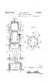
- This invention relates to internal combusfresh charge is entering the combustion chamtion engines, and more particularly to deher. 7 'vices of this character of the two-cycle type, i Fig. 4 isa horizontal section taken on the but'it is to be understood that an engine emline 44 of'Fig: 1. j V f 5 bodying the principles of this invention may Fig. 5 is a horizontalsection taken approxi- 55 be constructed for four-cycle or sixi-cycleopmately on the line 5 5 of Fig. 2. i V eration.
- character 1 designates generally provide, in amanner as hereinafter set forth, the cylinder, of the engine and comprises a 7 10 an engine of the aforementioned character lower portion or section 2 and an uppersec- 60 wherein the exhaust and intake operations tion 3 or less diameter than said section 2.
- Fig. 2 is a vertical sectional View showing the sectlon 2 of the e and upper the relative positions of the parts when the Section or extension 12 ofless diemeterthan exhaust operation is taking place'and when E SeCt1On 11 a p for pm 0 the incoming-gases have been drawn into the 111 the sectlfm 3 of t y n 1- lower chamber of the cylinder.
- the sect on 11 1s provided with sealing Fig, 3 is a vertical sectional View showing rings 13adjacent its upper end and the sec the relative position of the parts when the tion 12, is provided with-sealing, rings 14'adjacent its upper end.
- the section 11 of the piston is provided with a wrist pin 15 which is provided for connecting the connecting rod 16 thereto and, asusual, the'lower end of the connecting rod 16 is coupled to a crank shaft 17 V x
- the lower end of the cylinder 1 is adapted to be coupled to a crank case, not shown, and is provided with an annular flange 18.
- a The crank case of the engine is to have mounted therein a pair of vertically spaced bars 19 and 20, the purpose of which will bepresently set forth, On diametrically opposite sides,
- the reciprocating head 4 is provided with outwardly extending lugs or arms 21 having vertical bores extending therethru for the reception of the upper end of a pair of elongated lift rods 22'which are secured rigidly in the arms 21 in any suitable manner.
- the lift rods22 extendslidinglythrough openings in the flange 18,.b ar 19 and bar 20 in the crank case and terminate a distance below saidbar 20. j. f 3
- the bar 19 is of a configuration to avoid contact with the crankshaft 17.
- a cross rod connects the lift rods 22 intermediate the I 7 bars 19 and 20 and expansible coiled springs 24 encircle said lift rods .and impinge the' rods 23 and the lower guide rod 20.
- Aroller 25 is mounted'on the coupling rod' 23 beneath V the crank sh'aftl 'l'. Rigidly mounted on said crank shaft 17 is a cam 26 of a suitable configuration with which the'roller 25 is maintained in constant engagement through the 7 medium of the spring 24, as will be obvious.
- An intake conduit 27 communicates with theinterior of the section 20f the cylinder at its upper end through the medium of the intake valve 28, which is actuated in any suit able manner.
- the cylinders, piston, and reciprocating head receive their lubrication by the splash system from the crank case and the oil works itsway up between the sections 2 and 3 of the cylinder and the sect-ions 11 through the chamber 29 and 12 of thepiston, and in so doing, it'passes v which is warmed'by sa1d section 20f the cylinder and 11 of the piston. Owing to the greater size of the section 11 and its closer proximity to the crank case, more oil will enter the chamber .29 than will workupwardly between the piston section 12 and the cylinder section 3, and
- this oil enters the ducts 7 anddischarges into the recesses or grooves 6 ma manner to lu- 1 bricate the side walls of said reciprocating head and the adjacent outer walls and rings on the section 3.
- a plurality of elongated substantially'U-shaped conduits 3O communicats at their upper ends with the lower ends of said recesses and extending a distance therebelow' where they connect with conjductor plates 31' extending downwardly through the wall of'the cylinder section 2 and communicating with the interior of the crank case.
- the cam26 has rotated .to' a position which permits the spring 24 to raise the head 42 through the'medium of the lift rods 22 and When the piston starts on its upstroke,
- the segmental grooves or channels 6 establish communication between the upperfends of said ducts 7 and the interior of the head.
- ton is driven downwardly on 2 the power stroke inthe usual manner.
- a slightlylowerplace' on the cam 26 engages the roller 25 and permits a very slight" upward movement'of the head 4 at the time the explosion takes place, to. eliminate what is commonly known as knocking 'or compression'knocks.
- valve 28 closes as soon as the upstroke, l a V
- An engine of the character described comprising a cylinder having upper and lower sections, said lower section being of greater diameter than the upper section, a piston having upper and lower sections mounted for reciprocation in the corresponding sections of the cylinder, a reciprocating compression head enclosing the upper end of the upper section and communicating with the interior thereof, a valve for supplying fuel to the interior of the lower section of the cylinder, the upper section of the cylinder being provided with a plurality of passages extending from an upper peripheral portion to the lower end thereof and communicating with the lower portion of the cylinder for the reception of fuel therefrom, the compression head being provided with longitudiinvention, what nally extending recesses in the inner wall thereof adapted for registry with the passages upon reciprocation of said head in a manner to establish communication between said passages and the interior of the compression head, said passages and the recesses constituting means for conducting the fuel from the lower cylinder section to the interior of the compression head, and means for rapidly lowering the compression head on the cylinder
- An engine of the character described comprising a cylinder having a lower section, and means for supplying fuel thereinto, an upper section on said lower section of smaller diameter than said lower section, a piston comprising a lower section mounted for reciprocation in the corresponding section of the cylinder and an upper section for reciprocation in the upper section of the cylinder, a vertically reciprocating compression head slidably mounted on the upper portion of the upper cylinder section, said compression head and the upper cylinder section being provided with passages adapted to be peroidically brought into communication with each other in a manner to establish communication between the lower cylinder section and the cam mounted on said crank shaft, and means engageable with the cam and connected to the compression head for lowering same on the cylinder while the piston is in substantially its uppermost position for compressing the fuel charge therein.
- An internal combustion engine of the 'a reciprocating compression head mounted for longitudinal sl1d1ng movement on the i upper cylinder sectlon, said compresslon head and cylinder section being provided with a series of circumferentially spaced coacting passages adapted to be periodically brought into communication with each other by the reciprocation of the compression head in a manner to establish communication between the interior of said head and the interior of the lower cylinder section, said upper cylinder section being further provided with radially extending exhaust passages adapted to '5 v be closed by the adjacent cylinder section,
- crank shaft operatively connected to the piston, a cam mounted onsaid crankshaft,
Landscapes
- Engineering & Computer Science (AREA)
- Chemical & Material Sciences (AREA)
- Combustion & Propulsion (AREA)
- Mechanical Engineering (AREA)
- General Engineering & Computer Science (AREA)
- Cylinder Crankcases Of Internal Combustion Engines (AREA)
Description
Mai'ch 29, 1932. w. s. STEWART INTERNAL COMBUSTION ENGINE Ori inal Filed Oct. 2, 1929 3 Sheets-She et 1 70 Inventor l l a/fer J? Jfen/arf Ati March 29,1932, w 5 T T 1,851,530
INTERNAL COMBUSTION ENGINE Original Filed Oct. 2, 1929 3 Sheets-Sheet 2 Inventor 20 w/fel" Q9. (Syd/var? By 2mm;
A iiorney I Patented Mar. 29, 1932 a g g v i ,l iv
UNITED STATES PATENT oFFiciEY Application filed October 2, 1929, Serial N;396,762. Renewed September 4, 1931.v
This invention relates to internal combusfresh charge is entering the combustion chamtion engines, and more particularly to deher. 7 'vices of this character of the two-cycle type, i Fig. 4 isa horizontal section taken on the but'it is to be understood that an engine emline 44 of'Fig: 1. j V f 5 bodying the principles of this invention may Fig. 5 is a horizontalsection taken approxi- 55 be constructed for four-cycle or sixi-cycleopmately on the line 5 5 of Fig. 2. i V eration. Referring to the drawings indetailQthe An important objectof the invention is to reference character 1 designates generally provide, in amanner as hereinafter set forth, the cylinder, of the engine and comprises a 7 10 an engine of the aforementioned character lower portion or section 2 and an uppersec- 60 wherein the exhaust and intake operations tion 3 or less diameter than said section 2. are caused when the piston is in distinctly The upper portion of the section 3 is adapted different positions in the cylinder, thus elimfor telescopic distortion in aevertically re inating the danger of pre-ignition which ciprocating head& in the closedupper end often occurs in conventional two-cycle enof which is a spark plug 5; Adj acentits low- 55 gines' due to the incoming gas contacting er end and on itsinner periphery, therecipwith the hot exhaust gases which have not rocatinghead 4: is provided with aseries of completely left the cylinder. circumferentially spaced segmental recesses g Another important object of the invention or grooves 6.- i V is to provide an engine of the aforementioned The walls'of the section 3 of the cylinder, 70 character wherein a vertically reciprocating are provided with circumferentially spaced cylinder head is utilized for the purpose of ducts 7 which communicate at their lower compressing theexplosive charge and whereendswith the interior of the section 2 andare in said reciprocating head constitutes the turned outwardly at right angles adjacent major portion of the combustion chamber. the top of saidsection and are adapted'to 75 Other objects of the invention are to probe brought into communication with the vids an internal combustion engine of the grooves or recesses 6 of the reciprocating aforementioned character which will be simhead 4. V y
ple in construction, strong, durable, eflicient Packing rings 8'are mounted onthe upper '30 in its use,':and which may be manufactured end portions of the section 3 on opposite sides at l w o t, of the adjacent terminals of the ducts 7 for Other objects and advantages of the invenengagement With the inner walls of the reciption. will become apparent from a study of rocating head 4 for sealing the joint therebethe following specification, taken 1n connectween Adj t it l d f ti g H W h accompanying drawings W is provided with a plurality of radially exin like characters of references designate t di h t d it g hi h s be- Prrespondmg Pa throughout the Save-m1 tween the ducts 7 and communicate with the i i fifi is sie ftical sectional view show interior 0f said Section; I i i i 10 ing the position of the piston and the recip- A plst'on deslgnated generally by the refer 00 e v I ence character 10 is mounted for reciprocarocatmg head as Well as an of the movmg' tion in the cylinder 1 and comprisesamain P rts of the engine at the tune the explosion or s section 1 mounted pr a takes place in the combustion chamber. c V v, p i
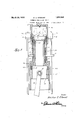
Fig. 2 is a vertical sectional View showing the sectlon 2 of the e and upper the relative positions of the parts when the Section or extension 12 ofless diemeterthan exhaust operation is taking place'and when E SeCt1On 11 a p for pm 0 the incoming-gases have been drawn into the 111 the sectlfm 3 of t y n 1- lower chamber of the cylinder. 1 The sect on 11 1s provided with sealing Fig, 3 is a vertical sectional View showing rings 13adjacent its upper end and the sec the relative position of the parts when the tion 12, is provided with-sealing, rings 14'adjacent its upper end. The section 11 of the piston, is provided with a wrist pin 15 which is provided for connecting the connecting rod 16 thereto and, asusual, the'lower end of the connecting rod 16 is coupled to a crank shaft 17 V x The lower end of the cylinder 1 is adapted to be coupled to a crank case, not shown, and is provided with an annular flange 18. a The crank case of the engine is to have mounted therein a pair of vertically spaced bars 19 and 20, the purpose of which will bepresently set forth, On diametrically opposite sides,
the reciprocating head 4 is provided with outwardly extending lugs or arms 21 having vertical bores extending therethru for the reception of the upper end of a pair of elongated lift rods 22'which are secured rigidly in the arms 21 in any suitable manner. The lift rods22 extendslidinglythrough openings in the flange 18,.b ar 19 and bar 20 in the crank case and terminate a distance below saidbar 20. j. f 3
The bar 19 is of a configuration to avoid contact with the crankshaft 17. A cross rod connects the lift rods 22 intermediate the I 7 bars 19 and 20 and expansible coiled springs 24 encircle said lift rods .and impinge the' rods 23 and the lower guide rod 20. Aroller 25 is mounted'on the coupling rod' 23 beneath V the crank sh'aftl 'l'. Rigidly mounted on said crank shaft 17 is a cam 26 of a suitable configuration with which the'roller 25 is maintained in constant engagement through the 7 medium of the spring 24, as will be obvious.
An intake conduit 27 communicates with theinterior of the section 20f the cylinder at its upper end through the medium of the intake valve 28, which is actuated in any suit able manner. 'The cylinders, piston, and reciprocating head receive their lubrication by the splash system from the crank case and the oil works itsway up between the sections 2 and 3 of the cylinder and the sect-ions 11 through the chamber 29 and 12 of thepiston, and in so doing, it'passes v which is warmed'by sa1d section 20f the cylinder and 11 of the piston. Owing to the greater size of the section 11 and its closer proximity to the crank case, more oil will enter the chamber .29 than will workupwardly between the piston section 12 and the cylinder section 3, and
this oil enters the ducts 7 anddischarges into the recesses or grooves 6 ma manner to lu- 1 bricate the side walls of said reciprocating head and the adjacent outer walls and rings on the section 3.
For taking care of an excess of lubricating I oil in the recesses 6, a plurality of elongated substantially'U-shaped conduits 3O communicats at their upper ends with the lower ends of said recesses and extending a distance therebelow' where they connect with conjductor plates 31' extending downwardly through the wall of'the cylinder section 2 and communicating with the interior of the crank case. I
The inner side of the members 30 engage V the peripheral'walls of the section 3 and are closed thereby. In the operation of the engine, the piston 10 is moved to the position shown in Fig.2 of the drawings, the intake valve 28 opens and a charge of fuel is drawn haustion ofthe gases and at the momentwhen the exhaust ports 9 are uncovered, the highest position or point on the cam 26 engages the roller 25 and the reciprocating cylinder head is brought rapidly. down to a position closely adjacent the upper end 0 the cylinder for the purpose of ejecting'zprac- 7 tically all of the exhaustgases,therefrom.
the cam26 has rotated .to' a position which permits the spring 24 to raise the head 42 through the'medium of the lift rods 22 and When the piston starts on its upstroke,
the fuel charge which has entered the chamber 29 is compressed in said chamber andthe ducts 7 until'the heads 4 reaches the'posi-r tion shown in Fig.3 of the drawings, when.
j the segmental grooves or channels 6 establish communication between the upperfends of said ducts 7 and the interior of the head.
At this time, another comparatively high place on the cam 26 engages the roller 25 and the head 4 is brought rapidly downwardly I to compress the charge therein. As soon as the head 4 reaches the limitiofthis compression stroke, the charge exploded through the medium of, the spark plug trend the pis-.,
ton is driven downwardly on 2 the power stroke inthe usual manner. As soon as the piston reaches the uppermost point' of the "compression stroke, a slightlylowerplace' on the cam 26 engages the roller 25 and permits a very slight" upward movement'of the head 4 at the time the explosion takes place, to. eliminate what is commonly known as knocking 'or compression'knocks.
valve 28 closes as soon as the upstroke, l a V It is believed that the many advantages of an engine constructed in accordance with this invention will be readily understood, and although the, preferred" embodiment of the invention is as illustrated anddescribed, it is to be understood that changes in the details. of construction may-be had, which the pistonstarts It is understood, of course, that the intake will fall within the scope of the invention as claimed.
Having thus described my I claim as new is 1. An engine of the character described comprising a cylinder having upper and lower sections, said lower section being of greater diameter than the upper section, a piston having upper and lower sections mounted for reciprocation in the corresponding sections of the cylinder, a reciprocating compression head enclosing the upper end of the upper section and communicating with the interior thereof, a valve for supplying fuel to the interior of the lower section of the cylinder, the upper section of the cylinder being provided with a plurality of passages extending from an upper peripheral portion to the lower end thereof and communicating with the lower portion of the cylinder for the reception of fuel therefrom, the compression head being provided with longitudiinvention, what nally extending recesses in the inner wall thereof adapted for registry with the passages upon reciprocation of said head in a manner to establish communication between said passages and the interior of the compression head, said passages and the recesses constituting means for conducting the fuel from the lower cylinder section to the interior of the compression head, and means for rapidly lowering the compression head on the cylinder when the piston is substantially in its uppermost position in a manner to compress the fuel charge therein.
2. An engine of the character described comprising a cylinder having a lower section, and means for supplying fuel thereinto, an upper section on said lower section of smaller diameter than said lower section, a piston comprising a lower section mounted for reciprocation in the corresponding section of the cylinder and an upper section for reciprocation in the upper section of the cylinder, a vertically reciprocating compression head slidably mounted on the upper portion of the upper cylinder section, said compression head and the upper cylinder section being provided with passages adapted to be peroidically brought into communication with each other in a manner to establish communication between the lower cylinder section and the cam mounted on said crank shaft, and means engageable with the cam and connected to the compression head for lowering same on the cylinder while the piston is in substantially its uppermost position for compressing the fuel charge therein.
3. An internal combustion engine of the 'a reciprocating compression head mounted for longitudinal sl1d1ng movement on the i upper cylinder sectlon, said compresslon head and cylinder section being provided with a series of circumferentially spaced coacting passages adapted to be periodically brought into communication with each other by the reciprocation of the compression head in a manner to establish communication between the interior of said head and the interior of the lower cylinder section, said upper cylinder section being further provided with radially extending exhaust passages adapted to '5 v be closed by the adjacent cylinder section,
the crank shaft operatively connected to the piston, a cam mounted onsaid crankshaft,
7 arms extending laterally from the compression head, vertical lift rods anchored in said arms and extending downwardly on opposite 1 sides of the crank shaft, expansible coiled springs associated with said rods in a manner to urge the compression head upwardly on the cylinder, and means carried by said rod engageable with the cam for shifting the compression head downwardly on the cylinder through the medium of said lift rodsand against the tension of the coiled springs for compressing the fuel charge in said head when the piston is substantially in its uppermost position in the cylinder.
In testimony whereof I affix my signature.
WALTER SCOTT STEWART.
Priority Applications (1)
| Application Number | Priority Date | Filing Date | Title |
|---|---|---|---|
| US396762A US1851530A (en) | 1929-10-02 | 1929-10-02 | Internal combustion engine |
Applications Claiming Priority (1)
| Application Number | Priority Date | Filing Date | Title |
|---|---|---|---|
| US396762A US1851530A (en) | 1929-10-02 | 1929-10-02 | Internal combustion engine |
Publications (1)
| Publication Number | Publication Date |
|---|---|
| US1851530A true US1851530A (en) | 1932-03-29 |
Family
ID=23568522
Family Applications (1)
| Application Number | Title | Priority Date | Filing Date |
|---|---|---|---|
| US396762A Expired - Lifetime US1851530A (en) | 1929-10-02 | 1929-10-02 | Internal combustion engine |
Country Status (1)
| Country | Link |
|---|---|
| US (1) | US1851530A (en) |
Cited By (4)
| Publication number | Priority date | Publication date | Assignee | Title |
|---|---|---|---|---|
| WO2001057377A1 (en) * | 2000-02-02 | 2001-08-09 | Normand Beaudoin | Mechanical discharge self-supercharging engine |
| CN101624936B (en) * | 2009-08-03 | 2014-03-19 | 靳北彪 | Self compression timing gas occupied suspension piston engine |
| CN101660448B (en) * | 2009-10-09 | 2014-07-16 | 靳北彪 | Slide-cylinder gas distribution suspending piston engine |
| RU2752214C2 (en) * | 2016-08-30 | 2021-07-23 | Сесар МЕРСИЕР | Two-stroke engine with valves activated by air pressure near the bottom dead point |
-
1929
- 1929-10-02 US US396762A patent/US1851530A/en not_active Expired - Lifetime
Cited By (4)
| Publication number | Priority date | Publication date | Assignee | Title |
|---|---|---|---|---|
| WO2001057377A1 (en) * | 2000-02-02 | 2001-08-09 | Normand Beaudoin | Mechanical discharge self-supercharging engine |
| CN101624936B (en) * | 2009-08-03 | 2014-03-19 | 靳北彪 | Self compression timing gas occupied suspension piston engine |
| CN101660448B (en) * | 2009-10-09 | 2014-07-16 | 靳北彪 | Slide-cylinder gas distribution suspending piston engine |
| RU2752214C2 (en) * | 2016-08-30 | 2021-07-23 | Сесар МЕРСИЕР | Two-stroke engine with valves activated by air pressure near the bottom dead point |
Similar Documents
| Publication | Publication Date | Title |
|---|---|---|
| US1565184A (en) | Internal-combustion engine | |
| US10513927B2 (en) | Internal combustion engine | |
| US1045505A (en) | Two-stroke-cycle internal-combustion engine. | |
| US4203406A (en) | Expanding piston | |
| US1851530A (en) | Internal combustion engine | |
| US1533926A (en) | Internal-combustion engine | |
| US2122677A (en) | Internal combustion engine | |
| US1281669A (en) | Internal-combustion engine. | |
| US1079622A (en) | Internal-combustion engine. | |
| US1764386A (en) | Sleeve-valve gas engine | |
| US1568964A (en) | Internal-combustion engine | |
| US1662740A (en) | Internal-combustion engine | |
| US1491940A (en) | Internal-combustion engine | |
| US1270295A (en) | Internal-combustion engine. | |
| US1461089A (en) | Internal-combustion engine | |
| US2545946A (en) | Internal-combustion engine | |
| US1666941A (en) | Internal-combustion engine | |
| US2269945A (en) | Internal combustion engine | |
| US946158A (en) | Internal-combustion engine. | |
| US1568391A (en) | Rotary internal-combustion engine | |
| US1854285A (en) | Internal combustion engine | |
| US1710083A (en) | Internal-combustion engine | |
| US1356865A (en) | Internal-combustion engine | |
| US1513310A (en) | Internal-combustion engine | |
| US1360689A (en) | Two-cycle gas-motor |