US1851527A - Separator - Google Patents
Separator Download PDFInfo
- Publication number
- US1851527A US1851527A US441789A US44178930A US1851527A US 1851527 A US1851527 A US 1851527A US 441789 A US441789 A US 441789A US 44178930 A US44178930 A US 44178930A US 1851527 A US1851527 A US 1851527A
- Authority
- US
- United States
- Prior art keywords
- disks
- stem
- passages
- cream
- disk
- Prior art date
- Legal status (The legal status is an assumption and is not a legal conclusion. Google has not performed a legal analysis and makes no representation as to the accuracy of the status listed.)
- Expired - Lifetime
Links
- 239000006071 cream Substances 0.000 description 15
- 239000000470 constituent Substances 0.000 description 9
- 239000007788 liquid Substances 0.000 description 6
- 235000008939 whole milk Nutrition 0.000 description 6
- 230000004048 modification Effects 0.000 description 2
- 238000012986 modification Methods 0.000 description 2
- 238000000926 separation method Methods 0.000 description 2
- 235000017276 Salvia Nutrition 0.000 description 1
- 241001072909 Salvia Species 0.000 description 1
- 238000010276 construction Methods 0.000 description 1
- 235000013367 dietary fats Nutrition 0.000 description 1
- 239000010520 ghee Substances 0.000 description 1
- 235000019988 mead Nutrition 0.000 description 1
- 239000002184 metal Substances 0.000 description 1
- 235000013336 milk Nutrition 0.000 description 1
- 239000008267 milk Substances 0.000 description 1
- 210000004080 milk Anatomy 0.000 description 1
- 239000000203 mixture Substances 0.000 description 1
- 235000020183 skimmed milk Nutrition 0.000 description 1
- 210000005239 tubule Anatomy 0.000 description 1
Images

Classifications
-
- B—PERFORMING OPERATIONS; TRANSPORTING
- B04—CENTRIFUGAL APPARATUS OR MACHINES FOR CARRYING-OUT PHYSICAL OR CHEMICAL PROCESSES
- B04B—CENTRIFUGES
- B04B7/00—Elements of centrifuges
- B04B7/08—Rotary bowls
- B04B7/12—Inserts, e.g. armouring plates
- B04B7/14—Inserts, e.g. armouring plates for separating walls of conical shape
Definitions
- Still anotherobject is separator having aplurality of channels per Patented Mar. 29,1932
- the invention' relates to centrifugal separator which eliminates the necessity of sepa-f rated portions passing back-through the 1ncoming u'nseparated' portions in order to pass out from the machine.
- Another object is to provide such a sepa'rator having a plurality-of'radially spacedpassages-for leading ofi theseparated portion as soon as it is 'separatedr Inittingthe incoming liquid to flow directly to, the disk on'which: separation of thatpor tion-of the liquidtakes place without having to pass through the other disks.
- i Fig. 3 is a plan view ofthe bowlassembly with the bowl cover removed.
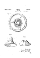
- I f Fig. 4 is a reduced perspective viewof the dividingdisk.
- 1 f1 Fig. 5 is a'reclu ed'perspective view of one ofthe skimming disk
- n i I Fig. 6 is a fragmentary section taken along. the line6of Fig.1. x v While the invention is susceptible of vari-. ous modifications and alternative constructions,' I have shown in the drawings and will herein describe.
- W a n Z l/Vhile the invention isadap'ted fo'risepai rating the lighter and heavier constituents i ofvarious liquids, for purposes of clarity it is described herein as: lCJBlIIg-lBGClfOIf separating cream aridiskiin-hailk; f; f "i":
- the bowl assembly is adapted to be .inounted Jon the upper end of a drive shaft and to, 'be rotated at a high; constanthpeedthereby;
- the bowl assembly comprises: in gen- Q eral a central stem, a pluralityof'skimming' disks surrounding said stem, 1neansjformed on said stem for. introducing the' whole-milk directlytherefrom to eachdisk, andxtwo sets of creamexit passages througlrsaidfdisks,
- a stem llOfisf provided which is tubular"in .form and open, at its top; Abowl 11 having a' -conical botef' tom and iuptu'rned sides; is rigidly attached to the lower end of thejstem'so that the lat-xter projects centrally upward from thefbottom of the bowl 11.
- The'stem 10 is adapted to beseated'supon and driven by a'shaft (not ab V 1 1 shown) running ata high'rot ative'speed.
- bow-l cover 12 having a conical shape is adapt y ed to close the bowl 11f with 'a liquid-tight seal therebetween and to be rigidly held by a nut 13 threaded to the topofthe.
- skimming disks l4 there are a plurality of conical skimming disks l4.(see Fig. 1) centrally apertured' to, surround the stem '10 and held' in axially spacedrelation to each i other.” Covering the skimming disks 1413a dividing diskjl5 which, in conjunction i the stem 10 and with the bowl cover 12, pro; vides separate paths for the cream and skim ⁇ milk'respectively-to follow in passing out of the bowl.”"
- the stem 10' being tubular and open-at its top forms an inlet through which whole-milk may be introduced'to thebowh On the side i 1 o f the stem; a plurality of radially extending wings 16 are formed (see Figs. land 2) each of which, at its upper end, has a radial orifice '17 communicating with the -in-' ly downward from the orifice 17 past all of. the skimming disks 14;.
- the whole-milk mayfipass front the iainterior L1 of the a stem through the orifices 17 andidown in the chain nels 18"freely and'without restriction toeach skimming disk 14; c T
- said creameXit passages are angularly spaced from thejorificesvl'i and are closer to the axis of rotation than the outerendsofsaid orifices.
- Eacli' skimming disk is provided with a j I c hat.
- I have Pro id d? eparateriw ehh s a ⁇ plurality of holes "21 punched in the disk at the onterlendl ofsaidorifices; the 110-16521 mead; disk being alined with those ine t-he other disks ⁇ ; hus,a second set'of cream exit j Zpassagesisformedfwhichisrad-ially spaced;
- cgg I disks surrounding said stem and radially spaced therefrom to form a first set of exit I passages for the lighter constituent therebetween, said disks having a plurality of alined holes forming a second set of exit passages for the lighter constituent radially spaced from said first set, and a dividing disk overlying said disks and spaced from said stem to form an outlet forthe lighter constituent from said first set of exit passages, said dividing disk having grooves opening downwardly over said holes in saiddisks and extending radially therefrom to said outlet to permit the lighter constituent from saidsec- 0nd set of exit passages to pass to said outlet.
- a centrifugal separator the combination of a bowl, a stem through which unsepa rated liquid may be introduced centrally of said bowl, a plurality of separating disks mounted in said bowland having alined holes radially spaced from said stem and constituting a set of exit passages for the lighter constituent, and a dividing disk overlying said separating disks and having radial grooves opening downwardly over said holes 1 to form an outlet for the lighterconstituent from said exit passages.
- a bowl a plurality of separating disks each having a plurality of radially T spaced passages at different distances from the axis of the disks, and acting to carry off" different portions of the lighterconstituent as it is separated, and means adjacent the ends of said passages for permitting free egress of the lighter constituent from all of said passages, including an enlarged duct communicating with the passages at the greatest distance from the axis;
- a centrifugal cream separator having a plurality of separating disks each having an inner passage for one portion of thev separated cream and outer openingsat a greater radial distance from the axis of the disks for another portion of the separated cream, and a dividing disk covering said disks and having an outlet neck leading from said inner pas sages and also having grooves connecting said outer openings with said neck.
Landscapes
- Centrifugal Separators (AREA)
Description
P. B. SHEE Ma-uh 29, 1932,
Filed April 5, 1930 2 $h88tS-Sh68c 2 lnderzwn- Parke E- Ghee/- o ndal 944W MW.
PARKE B. SHEE,
16 Still anotherobject is separator having aplurality of channels per Patented Mar. 29,1932
UNITED swig or 0.413 PARK, rumors; AssreNoR' TO snARs, :RoE'nUcK Ann co pe 2 onioneo, ILLINOIS, econronarioivorkivnw YORKJQQ 1' snPARAroR A "The invention'relates to centrifugal separator which eliminates the necessity of sepa-f rated portions passing back-through the 1ncoming u'nseparated' portions in order to pass out from the machine. 3 I
Another object is to provide such a sepa'rator having a plurality-of'radially spacedpassages-for leading ofi theseparated portion as soon as it is 'separatedr Inittingthe incoming liquid to flow directly to, the disk on'which: separation of thatpor tion-of the liquidtakes place without having to pass through the other disks.
A still further object is toprovide a novel methodfor separating different constituentsofa'liquid. I V Q Other objects and advantages will become apparent from the following" description the accompanying taken in connection with drawings, in which: I g Y Figure 1 is a vertical section through a separator bowl assembly embodying the features 80 ofthe invention,
2 is a horizontal line 22 of Fig, 1,. I l
i Fig. 3 is a plan view ofthe bowlassembly with the bowl cover removed. I f Fig. 4 is a reduced perspective viewof the dividingdisk. 1 f1 Fig. 5 is a'reclu ed'perspective view of one ofthe skimming disk n i I Fig. 6 is a fragmentary section taken along. the line6of Fig.1. x v While the invention is susceptible of vari-. ous modifications and alternative constructions,' I have shown in the drawings and will herein describe. ,in detail the preferred em bodiment, but it is to, beunderstoodi-that I do not thereby intend to limit the invention to the specific form disclosed but-intend torcover all modifications and; alternative construetions falling within the spirit andsco'pe'of' section taken along the to provide 7 such a place "stemi 193 Serial No. 141, 759. i
the invention as expressed the l appended;
claims. W a n Z l/Vhile the invention isadap'ted fo'risepai rating the lighter and heavier constituents i ofvarious liquids, for purposes of clarity it is described herein as: lCJBlIIg-lBGClfOIf separating cream aridiskiin-hailk; f; f "i":
Ina centrifugal creainseparator, the bowl assembly is adapted to be .inounted Jon the upper end of a drive shaft and to, 'be rotated at a high; constanthpeedthereby; In the cream separator constituting the present invention, the bowl assembly comprises: in gen- Q eral a central stem, a pluralityof'skimming' disks surrounding said stem, 1neansjformed on said stem for. introducing the' whole-milk directlytherefrom to eachdisk, andxtwo sets of creamexit passages througlrsaidfdisks,
said sets being radially spaced: from each .ratedand the other to catch the=cream less easilyseparated inorder to prevent it p'a'ss other, one to catch the cream easily. sepaing back through the incoming wholeinilk.
" As shown in the-drawings, a stem llOfisf" provided which is tubular"in .form and open, at its top; Abowl 11 having a' -conical botef' tom and iuptu'rned sides; is rigidly attached to the lower end of thejstem'so that the lat-xter projects centrally upward from thefbottom of the bowl 11. The'stem 10 is adapted to beseated'supon and driven by a'shaft (not ab V 1 1 shown) running ata high'rot ative'speed. A'
bow-l cover 12 having a conical shape is adapt y ed to close the bowl 11f with 'a liquid-tight seal therebetween and to be rigidly held by a nut 13 threaded to the topofthe.
lVithin 'the-lbowl'jll there are a plurality of conical skimming disks l4.(see Fig. 1) centrally apertured' to, surround the stem '10 and held' in axially spacedrelation to each i other." Covering the skimming disks 1413a dividing diskjl5 which, in conjunction i the stem 10 and with the bowl cover 12, pro; vides separate paths for the cream and skim} milk'respectively-to follow in passing out of the bowl.""
; The stem 10' being tubular and open-at its top forms an inlet through which whole-milk may be introduced'to thebowh On the side i 1 o f the stem; a plurality of radially extending wings 16 are formed (see Figs. land 2) each of which, at its upper end, has a radial orifice '17 communicating with the -in-' ly downward from the orifice 17 past all of. the skimming disks 14;. Thus, the whole-milk mayfipass front the iainterior L1 of the a stem through the orifices 17 andidown in the chain nels 18"freely and'without restriction toeach skimming disk 14; c T
around' the wings -1 6 (seeFigQ 2.), one wing ming disks willialways be assembled in the I I same relationto'the stem. Theapertur'es are offsuchdiameter that theedges thereof are radially sp aced' fronithe main bod} of the stem' to'form gapsQO therebetween constituting a first of cream exit passages. Thus,
; said creameXit passages are angularly spaced from thejorificesvl'i and are closer to the axis of rotation than the outerendsofsaid orifices.
Eacli' skimming disk is provided with a j I c hat. I have Pro id d? eparateriw ehh s a} plurality of holes "21 punched in the disk at the onterlendl ofsaidorifices; the 110-16521 mead; disk being alined with those ine t-he other disks}; hus,a second set'of cream exit j Zpassagesisformedfwhichisrad-ially spaced;
from said first set; i Y
' ,A portionof the metal punchedout of ieach hole 21 isleft attached to the outer edge of the-hole'and'is bentb'aek ontov theupper Surface oflthe' disk-toiproyide a caulk 19 by" which thed isks are held: in their spaced rela- J tion. 1- Caulks adjacent the outer edges of the may: be provided as weldingsmall pieces wof rnetaltothe upper surfaces of the disks' c disks l 'f rorn the channels 18, and the cream eas ly; separated, being'light' i l-weight, n
7 7 immediately "lag :behind' the channel from whichit'cameandbe forcedradiallyinward around the ,followiiig' edges of thewings where it is caught in the firstset of creamexit assages, The cream lesseasily separated, aving already passed part wayout to the V periphery of the skimming. disks before it is separated, and being" light in iw eight, lags;
behind 1 the incomin whole-milk and is caught the second settof cream exit-passages, the'skim-milk passing on out to the pc- 7 r iphery.of thedisks. Thus,'noneof the cream,
has -to pass back c through the. incoming stream of whole-milk and}, large part ofa th separation may take placeclose to the T wings d r d hg-di 1-. wh ch was he ine the skimming diskstsee vFig. 3)',I-a p111; .rality of downwardlyopeningi grooves 26 The edges ofthe centralapertures in skimming disks-are notched toifit" closely 'Plu alityef em rs 27 1 a pa ed e a nt liebevl ev r 2 far w u l t 8- points angularly 'spaced fromthe orifices 1 7 andffarther frointhe axis of rotation than;
permitting the incomingiunseparated liquid flew direc ly e h disk-0 wh ch h en i I f mbi a on, a t abifl r emz rni s minnu In separatmgcream from the slt m m lk r15) v the whole-milk passes onto the skimming by-th'e lighter constituent from said second skimming disks, is formedzwith a firstc'y lindrical portion QQ-capping. the main conical'part and a smaller'conical' portion 23 whose upper end blends abovethe wings 16 into a second cylindricalportion 2a which is radially spaced from the stem to form therewith a path 7 to an outlet tor the V cream. r r At points immediately above the holes 21 are formed in the dividing disk; vby placing a biil ge-in the 1netal,to extend from above a V 7' 'i saidholes radially inward to provide a duct by which thecre'am'from the-second set of a V 1 ream exi Passa es may-b le tie a P9 her t j ns the c m flowin from the fi s se 9f e -am e t ra se es nd th n e-r passes to the creaI l 0l Pl6t 25.
The d ng idisk We iich hold in he ew h apa s eji re .1 1 i es f, vthe; e i -beye ilthslp riplh r1 f th k mm n disks through which theslginr-rnilk may flow' t -e den remrth abet-e d sc pti w plurality of radially spaced ezgit passages h l e onst u t e actqu d shar aat? et ae c ss ty of aid;'Ql P%$ g: ack. h ne-h t e. ncomin Str am, f. 1 pa ated liqu n r er I t was item "th a hinajwhi h' es a eler l ty Qf hae l' at oz take yplese iv theet av verse through 'othergdis'ks and which,-
reason hereot e fe ts, theiro hl eneretion 0f h lighter cons tuen s ite -th heav wea tuents; gr w I claim as'my invention A c rif earete m ia e aim d bal s radially s a ed rem sa Pe tions forming a secondiset of exitfpassages for the lighter-constituent. anda dividing &9
disk c overi g'said disks aiid radiallyi spaced from said stem to form an-outlet" from-said first set ofexit 'passages, 'said dividing disk having downwardly openingfradi-al grooves overlying said" holes to provide duc'ts; whereset of exit passages may pass to: the; i'outlet ofrsaid'firstsetof exit passages. 1
2; In a centrifugaljiseparator, a, tubules stem thro ghwh ch;unsepanated liquid;may;
e, introduced, a plurality; -o.f-- axiallywspaced:
cgg I disks surrounding said stem and radially spaced therefrom to form a first set of exit I passages for the lighter constituent therebetween, said disks having a plurality of alined holes forming a second set of exit passages for the lighter constituent radially spaced from said first set, and a dividing disk overlying said disks and spaced from said stem to form an outlet forthe lighter constituent from said first set of exit passages, said dividing disk having grooves opening downwardly over said holes in saiddisks and extending radially therefrom to said outlet to permit the lighter constituent from saidsec- 0nd set of exit passages to pass to said outlet.
3. In a centrifugal separator, the combination of a bowl, a stem through which unsepa rated liquid may be introduced centrally of said bowl, a plurality of separating disks mounted in said bowland having alined holes radially spaced from said stem and constituting a set of exit passages for the lighter constituent, and a dividing disk overlying said separating disks and having radial grooves opening downwardly over said holes 1 to form an outlet for the lighterconstituent from said exit passages.
4. A centrifugal separator comprlsmg, in
combination, a bowl, a plurality of separating disks each having a plurality of radially T spaced passages at different distances from the axis of the disks, and acting to carry off" different portions of the lighterconstituent as it is separated, and means adjacent the ends of said passages for permitting free egress of the lighter constituent from all of said passages, including an enlarged duct communicating with the passages at the greatest distance from the axis;
5. A centrifugal cream separator having a plurality of separating disks each having an inner passage for one portion of thev separated cream and outer openingsat a greater radial distance from the axis of the disks for another portion of the separated cream, and a dividing disk covering said disks and having an outlet neck leading from said inner pas sages and also having grooves connecting said outer openings with said neck.
In testimony whereof, I have hereunto affixed my signature. PARKE B. SHEE.
Priority Applications (1)
| Application Number | Priority Date | Filing Date | Title |
|---|---|---|---|
| US441789A US1851527A (en) | 1930-04-05 | 1930-04-05 | Separator |
Applications Claiming Priority (1)
| Application Number | Priority Date | Filing Date | Title |
|---|---|---|---|
| US441789A US1851527A (en) | 1930-04-05 | 1930-04-05 | Separator |
Publications (1)
| Publication Number | Publication Date |
|---|---|
| US1851527A true US1851527A (en) | 1932-03-29 |
Family
ID=23754284
Family Applications (1)
| Application Number | Title | Priority Date | Filing Date |
|---|---|---|---|
| US441789A Expired - Lifetime US1851527A (en) | 1930-04-05 | 1930-04-05 | Separator |
Country Status (1)
| Country | Link |
|---|---|
| US (1) | US1851527A (en) |
Cited By (2)
| Publication number | Priority date | Publication date | Assignee | Title |
|---|---|---|---|---|
| US5477021A (en) * | 1990-02-24 | 1995-12-19 | Westfalia Separator | Centrifuge-drum disk |
| US6526794B1 (en) | 1998-04-15 | 2003-03-04 | Südmo Schleicher AG | Plate for the spin drum of a centrifuge with spacers and process for its manufacture |
-
1930
- 1930-04-05 US US441789A patent/US1851527A/en not_active Expired - Lifetime
Cited By (2)
| Publication number | Priority date | Publication date | Assignee | Title |
|---|---|---|---|---|
| US5477021A (en) * | 1990-02-24 | 1995-12-19 | Westfalia Separator | Centrifuge-drum disk |
| US6526794B1 (en) | 1998-04-15 | 2003-03-04 | Südmo Schleicher AG | Plate for the spin drum of a centrifuge with spacers and process for its manufacture |
Similar Documents
| Publication | Publication Date | Title |
|---|---|---|
| US6183407B1 (en) | Centrifugal separator having axially-extending, angled separation discs | |
| EP1991337B1 (en) | Centrifugal separator | |
| US2599619A (en) | Method and apparatus for centrifugal separation | |
| EP0534943B1 (en) | Method and plant for freeing a liquid from a substance dispersed therein and having a larger density than the liquid | |
| US6602180B2 (en) | Self-driven centrifuge with vane module | |
| JPS62102846A (en) | Inflow apparatus for centrifugal separator | |
| GB1565438A (en) | Nozzle type centrifugal machine with slurry pumping chambers | |
| US1851527A (en) | Separator | |
| SE504007C2 (en) | Centrifugal separator inlet device | |
| EP1068016A1 (en) | Rotor for centrifugal separator | |
| JP3960361B2 (en) | centrifuge | |
| GB460362A (en) | Improvements in or relating to centrifugal separators | |
| US3777972A (en) | Sludge centrifuge | |
| CA1115649A (en) | Apparatus for separating or concentrating gaseous mixtures | |
| US993791A (en) | Liner for centrifugal liquid-separators. | |
| US1634759A (en) | Centrifugal milk separator | |
| US694736A (en) | Liner for centrifugal liquid-separators. | |
| US2039127A (en) | Rotary dust separator | |
| US3438571A (en) | Centrifugal separator | |
| US1256810A (en) | Froth-reducing discharge apparatus and process. | |
| US2224617A (en) | Rotary dust separator impeller | |
| US432719A (en) | von bechtolsheim | |
| EP1142644B1 (en) | Self-driven centrifuge with separation vane module | |
| US1721230A (en) | Centrifugal separator | |
| US640358A (en) | Centrifugal cream-separator. |