US1851516A - Indicating chart - Google Patents
Indicating chart Download PDFInfo
- Publication number
- US1851516A US1851516A US506232A US50823231A US1851516A US 1851516 A US1851516 A US 1851516A US 506232 A US506232 A US 506232A US 50823231 A US50823231 A US 50823231A US 1851516 A US1851516 A US 1851516A
- Authority
- US
- United States
- Prior art keywords
- chart
- cylinder
- spiders
- aluminum
- indicating
- Prior art date
- Legal status (The legal status is an assumption and is not a legal conclusion. Google has not performed a legal analysis and makes no representation as to the accuracy of the status listed.)
- Expired - Lifetime
Links
- 241000239290 Araneae Species 0.000 description 31
- 229910052782 aluminium Inorganic materials 0.000 description 16
- XAGFODPZIPBFFR-UHFFFAOYSA-N aluminium Chemical compound [Al] XAGFODPZIPBFFR-UHFFFAOYSA-N 0.000 description 16
- 238000005303 weighing Methods 0.000 description 9
- 238000000034 method Methods 0.000 description 5
- 239000000463 material Substances 0.000 description 4
- 229910052751 metal Inorganic materials 0.000 description 4
- 239000002184 metal Substances 0.000 description 4
- 238000010521 absorption reaction Methods 0.000 description 3
- 238000010276 construction Methods 0.000 description 3
- TWNQGVIAIRXVLR-UHFFFAOYSA-N oxo(oxoalumanyloxy)alumane Chemical compound O=[Al]O[Al]=O TWNQGVIAIRXVLR-UHFFFAOYSA-N 0.000 description 2
- GRYLNZFGIOXLOG-UHFFFAOYSA-N Nitric acid Chemical compound O[N+]([O-])=O GRYLNZFGIOXLOG-UHFFFAOYSA-N 0.000 description 1
- 101150034459 Parpbp gene Proteins 0.000 description 1
- 238000004140 cleaning Methods 0.000 description 1
- 239000011248 coating agent Substances 0.000 description 1
- 238000000576 coating method Methods 0.000 description 1
- 230000008021 deposition Effects 0.000 description 1
- 230000005484 gravity Effects 0.000 description 1
- OYIKARCXOQLFHF-UHFFFAOYSA-N isoxaflutole Chemical compound CS(=O)(=O)C1=CC(C(F)(F)F)=CC=C1C(=O)C1=C(C2CC2)ON=C1 OYIKARCXOQLFHF-UHFFFAOYSA-N 0.000 description 1
- 239000004922 lacquer Substances 0.000 description 1
- 229910001234 light alloy Inorganic materials 0.000 description 1
- 229910017604 nitric acid Inorganic materials 0.000 description 1
- 239000003973 paint Substances 0.000 description 1
- 238000007665 sagging Methods 0.000 description 1
- 230000003068 static effect Effects 0.000 description 1
- 239000000126 substance Substances 0.000 description 1
Images
Classifications
-
- G—PHYSICS
- G01—MEASURING; TESTING
- G01G—WEIGHING
- G01G23/00—Auxiliary devices for weighing apparatus
- G01G23/18—Indicating devices, e.g. for remote indication; Recording devices; Scales, e.g. graduated
- G01G23/20—Indicating weight by mechanical means
- G01G23/22—Indicating weight by mechanical means combined with price indicators
Definitions
- This invention relates to weighing scales such as are used in retail shops and in particular to suchscales which employ a rotatable cylindrical chart to indicate the weight'v and the computed money value of a commodity.
- the usual way of constructing these charts is to make alight framework over which a cylinder of paper is slipped on which the weight and value graduations are printed. ⁇ This paper cylinder 1s then fastened to the ⁇ framework by staples made of thin wire.
- va sheet of paper of a given size is' lighter than a sheet of aluminum of equal size; the. thickness of each sheet being suitable for the purpose; the assembled paper chart will weigh more, as owing to the hygroscopic qualities of'the paper it must be thoroughly sealed against absorption of tmospheric ⁇ moisture. lThis absorption by paper is not uniform and unlessy prevented entirely, the condition of static balance of the chart would soon be destroyed. Scale manufacturers therefore (seal the paper againstmoisture by applying several coats of lacquer. As many as seven coats have been applied to charts ⁇ intended to be used in the humid atmosphere of the tropics; an
- the primaryI4 object of this Ainvention is therefore the improved construction of an aluminum chart which is adapted to obviate the diiculties hereabove referred to.
- Another object of the invention is the provision of a chart of non-hygroscopic material.
- Another object of the invention is the provision of means for Vmaking a cylindrical chart for scales i-n which the thickened portion ofthe ,seam or joint is disposed in the interior of the cylinder leaving the periphery smooth and perfectly round.
- Another object of the invention is the provision lof means for treating the polished surface of a metallic chart'bymeans of chemical action sothat lit becomes non-reflecting.
- a still further object of the invention is the provision of means for fastening the cylinder to -a framework without the Laid of staples or other .extraneous means.
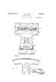
- Figure I is a front elevation of a cylinder embodying myimproved chart.
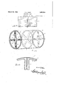
- Figure'IV is an enlarged fragmentary end elevation of the chart and frame showing the construction of the seam in detail.
- Figure V is an enlarged fragmentary portion of the chartand frame, a portion broken away substantially along the line V-V of Figure III and showing the method of fastening the chart cylinder to the frame.
- a base 1 suitably houses a load receiving lever mech-l anism (not shown) on which a load receiver 2 is mounted.
- a housing 3 contains a load counterbalancing mechanism which may be of any preferred type and which is operatively connected to an indicating mechanism located within the casing 4.
- This indicating mechanism comprises an aluminum chart 5 vin which the indicating surface is rendered non-,reflecting by the deposition of a coating of aluminum oxide.
- the chart 5 is exposed to view through an opening 6 in the casing 4.
- the chart 5 comprises a st eel shaft 7 upon which, adjacent the ends, chart spiders 8 and 1() are fastened to suitable hubs.
- the spiders may have any desired number of'arms; but 4 shown and described is to be regarded as 1lthe center of mass of each should be substantially at its axis.
- a pinion 7a is fastened adjacent one of the ends yand itis through this pinion that the reciprocating motion of the counterbalancing lmechanism is translated into rotation.v
- the spider 9 is located i1 termediate the spiders 8 and 10 and differs from them in that it is not fastened to the shaft,
- the purpose of the spider 9 is to prevent the central portion of the chart cylinder from sagging.
- the cylinder 11 is formed from a single sheet of aluminum.
- the folded seamv which connects the ends of the sheet from which the cylinderis formed, differs from the ordinary seam by the lfactv that its folds are adapted to be disposed entirely within the interior of the cylinder.4
- the outside lsurface is continuous and absolutely flush. As the chart is perfectly round, and there 1re no projections, an indicating wirel 12 can be stretched very close to the chart across the opening 6 inthe casing 5.
- the spiders 8, 9 and 10 have a small segment 14 cut out oftheir peri pheries see Figure IV) These segmental cutouts are substantially on the ⁇ longitudinal axis of a spider arm 15 so that the additional Weight of the folds may be counterbalanced by the weights 16 which are adjustable along the axis 4of the spider arms.
- the purpose of the adjustable weights 16 and 17 is to statically bal-ance the chart so that no force components are set up during rotation which tend to destroy the accuracy of the scales.
- weighing mechanism and indicating mechanism operated thereby, said indicating mechanism comprising a shaft, spiders of light material secured thereto and an aluminum cylinder surrounding said spiders,
- said aluminum cylinder having a folded seam below the surface thereof.
- said indicatin mechanism comprising a shaft, spiders o light material secured thereto, a cylinder of aluminum o r a light alloy containing aluminum surrounding said spiders, avlm of the aluminum at the exposed surface of said cylf inder having been converted to aluminuml 1 oxide.
- said indicating mechanism comprising a shaft, a plurality of spiders, each having arms secured to said shaft, a cylinder of light metal having an interlocked seam surrounding said spiders andcweights adjustable on the arms of a spider Yto counterbalance the weight of said interlocked seam.
- said indicating mechanism comprising a shaft, a plurality of circular spiders each having a plurality of arms secured to said shaft, the axes of said arms intersecting substantially at an angle of 90, a statically unbalanced cylinder of thin aluminum surrounding said spidersv and weights adjustable on said spider arms to statically balance said chart.
- said indicating mechanism comprising a shaft, a,plurality of spiders secured thereto having a circular periphery, a cylinder of light metal having an interlocked seam disposed in the interior of said cylinder surrounding said spiders and v each of said circular spiders having a por- 30 tion removed from its periphery to receive said interlocked seam.
- said in-I dicating mechanism including a spider having a clrcular periphery, a plurality of arms and a portion removed from the periphery ⁇ of said spider substantially on the axis of one of said arms.
- weighing mechanism in combination, weighing mechanism, indicatingl mechanism in co-oper'ation therewith, said indicating mechanism including a rotary chart comprising a cylinder of light metal, a light metallic framework having openings and portions of said cylinder forced into said openings to retain said cylinder to said framework.
- rotary chart comprising a cylinder formed from a sheet of thin aluminum having a nonglare surface of aluminum oxide, a framework including a plurality of spiders having a circular periphery and means formed by said cylinder and said spiders for fastening said cylinder to said spider.
- weighing mechanism in combination, weighing mechanism, indicating mechanism operatively connected thereto, said indicating mechanism including a chart comprisin a 6.5 shaft, -a plurality of anged circularspi ers fastened thereto, a cylinder of light, thinA aluminum having an interlocking seam disposed in the interior thereof, said spiders having portions removed as clearance for said interlocking seam, a plurality of spaced open-
Landscapes
- Physics & Mathematics (AREA)
- General Physics & Mathematics (AREA)
- Treatment Of Fiber Materials (AREA)
Description
March 29, 1932. 55,i N HUR-r 1,851,516
INDICATING CHART Filed Jan. l2, 1931 2 Sheets-Sheet l @L INVENTOR ATTORNEY March 29, 1932. s. N. HURTl INDICATING CHART Filed Jan. 12. 1951 2 Sheets-Sheet 2' amue//M/far INVENTOR.
A T TORNE Y.
Patented Mar. 29, 1932 UNITED STATES lPATENT ori-Ica SAMUEL N. HURT, OF TOLEDO, OHIO, ASSIGNOR TO TOLEDO SCALENMANUFACT'RING GOMPANY, OF TOLEDO, OHIO, lA CORPORATION OF NEW JERSEY mnrca'rme enana* I Application led January 12,1931. Seri-a1 No. 508,232.
This invention relates to weighing scales such as are used in retail shops and in particular to suchscales which employ a rotatable cylindrical chart to indicate the weight'v and the computed money value of a commodity. The usual way of constructing these charts is to make alight framework over which a cylinder of paper is slipped on which the weight and value graduations are printed.` This paper cylinder 1s then fastened to the `framework by staples made of thin wire. It has been attempted to substitute a sheet of thin aluminum for the paper on which'the indicia lare printed, but scales constructed with aluminum charts were soon abandoned as the construction, particularly the heretofore known methods of making the seam or vjoint and the method of retaining the .cylindrical sheet portion of the chart to the framework, were'unsatisfactory; In scales of this .kind an index line, which is usually a thin wire, mustbe stretched across the chart a very short distance from it to prevent errors in reading the indication due to parallax. The seams o r joints heretofore made, however, projected such a distance from the surface that the indicating wire had to be stretched a considerable distance awayfrom the chart to prevent the seamv from striking it. This resulted in agreat many errors due to the aforementioned parallax, Staples are used in fastening the paper cylinder to flush. When a sheet of aluminum is .use'd in v -the framework of cylinder sheets 'at the present time, but as paper is easil compressible, the staple is embedded an there- -fore the outer surface of the chartremams Y Attempts to obviate these objections by coat-' ing the surface with paint resulted in a prohi i tive increase in weight.
oo It is essential that rotary pari, 'such as the herein described chart, in scales, be as light as possible'so that the inertia, of the part, occasioned by the rotation, is as small as possible. The reason for this is obvious.
Although va sheet of paper of a given size is' lighter than a sheet of aluminum of equal size; the. thickness of each sheet being suitable for the purpose; the assembled paper chart will weigh more, as owing to the hygroscopic qualities of'the paper it must be thoroughly sealed against absorption of tmospheric `moisture. lThis absorption by paper is not uniform and unlessy prevented entirely, the condition of static balance of the chart would soon be destroyed. Scale manufacturers therefore (seal the paper againstmoisture by applying several coats of lacquer. As many as seven coats have been applied to charts` intended to be used in the humid atmosphere of the tropics; an
aluminum chart requires no special treatment against the absorption of. moisture and in spite of the' greater specific gravity of the material is considerably lighter than a paper` chart which must be fully protected.
The primaryI4 object of this Ainvention is therefore the improved construction of an aluminum chart which is adapted to obviate the diiculties hereabove referred to.
Another object of the invention is the provision of a chart of non-hygroscopic material.
Another object of the invention is the provision of means for Vmaking a cylindrical chart for scales i-n which the thickened portion ofthe ,seam or joint is disposed in the interior of the cylinder leaving the periphery smooth and perfectly round.
Another object of the invention is the provision lof means for treating the polished surface of a metallic chart'bymeans of chemical action sothat lit becomes non-reflecting.
A still further object of the invention is the provision of means for fastening the cylinder to -a framework without the Laid of staples or other .extraneous means.
Other objects and advantages will be a pa,- rent from the following description in which reference 'is had.`v i
In the drawings y Figure I is a front elevation of a cylinder embodying myimproved chart.
lan view of a cylinder chart showing a preerred method of fastening the chart cylinder to the frame.
Figure'IV is an enlarged fragmentary end elevation of the chart and frame showing the construction of the seam in detail.
Figure V is an enlarged fragmentary portion of the chartand frame, a portion broken away substantially along the line V-V of Figure III and showing the method of fastening the chart cylinder to the frame.
Scales employing cylindrical charts `of the type in which I have shown my invention embodied are well known and I will therefore describe the scale per se only so far as is necessary to properly disclose my invention.
Referring to the drawings in detail, a base 1 suitably houses a load receiving lever mech-l anism (not shown) on which a load receiver 2 is mounted. A housing 3 contains a load counterbalancing mechanism which may be of any preferred type and which is operatively connected to an indicating mechanism located within the casing 4. This indicating mechanism comprises an aluminum chart 5 vin which the indicating surface is rendered non-,reflecting by the deposition of a coating of aluminum oxide. The chart 5 is exposed to view through an opening 6 in the casing 4. The chart 5 comprises a st eel shaft 7 upon which, adjacent the ends, chart spiders 8 and 1() are fastened to suitable hubs. The spiders may have any desired number of'arms; but 4 shown and described is to be regarded as 1lthe center of mass of each should be substantially at its axis. A pinion 7a is fastened adjacent one of the ends yand itis through this pinion that the reciprocating motion of the counterbalancing lmechanism is translated into rotation.v The spider 9 is located i1 termediate the spiders 8 and 10 and differs from them in that it is not fastened to the shaft,
but is held in place by a cylinder of aluminumv 11 to which its periphery is -cemented. The purpose of the spider 9 is to prevent the central portion of the chart cylinder from sagging. The cylinder 11 is formed from a single sheet of aluminum. ,The folded seamv which connects the ends of the sheet from which the cylinderis formed, differs from the ordinary seam by the lfactv that its folds are adapted to be disposed entirely within the interior of the cylinder.4 The outside lsurface is continuous and absolutely flush. As the chart is perfectly round, and there 1re no projections, an indicating wirel 12 can be stretched very close to the chart across the opening 6 inthe casing 5.
the interior of the chart, the spiders 8, 9 and 10 have a small segment 14 cut out oftheir peri pheries see Figure IV) These segmental cutouts are substantially on the`longitudinal axis of a spider arm 15 so that the additional Weight of the folds may be counterbalanced by the weights 16 which are adjustable along the axis 4of the spider arms. The purpose of the adjustable weights 16 and 17 is to statically bal-ance the chart so that no force components are set up during rotation which tend to destroy the accuracy of the scales.
When the circular chart has been assembled to the spiders, it is fastened by an improved method Which does not add to the Weight of the chart nor form any projection beyond the outer surface which might interfere with the location of the index wire. lThis is accomplished by f piercingl a pointed instrument through the metallic cylinder of the flanges 18 and the spiders 8, 9, and 10. This operation forces a portion of the metal of the cylinder 11 into the puncture in the flange 18. As many of these punctures may be made as are necessary to securely hold and retain the cylinder on the spider. The result is shown" ily seen that the cylinder 11 is thereby rmly l secured to the framework consisting of the sh aft 7 and the spiders 8 and 10.
To provide a surface suitable for printing on the cylinder 11 it is proposed tov form a layer of laluminum oxide-thereon; this is readily accomplished by subjecting it to the action of concentrated nitric acid for a short time after first thoroughly cleaning the sheet; The resulting surface is white, non-reflecting and indicia printed thereon is easily read.
The embodiment of my invention herein lustrative only, and it isto be understood that the invention is susceptible to variation,
modilication and change within the spirit and scope of the subjoined claims.
Having described my invention, I claim:
1. In a device of the class described, in combination, weighing mechanism and indicating mechanism operated thereby, said indicating mechanism comprising a shaft, spiders of light material secured thereto and an aluminum cylinder surrounding said spiders,
said aluminum cylinder having a folded seam below the surface thereof.
2. In a device of the class described, in combination, weighing mechanism and indicating mechanism operated thereby, said indicatin mechanism comprising a shaft, spiders o light material secured thereto, a cylinder of aluminum o r a light alloy containing aluminum surrounding said spiders, avlm of the aluminum at the exposed surface of said cylf inder having been converted to aluminuml 1 oxide. To accommodate the folds of the seam 13v in combination, weighing mechanism and indieating mechanism operated thereby, said indicating mechanism comprising a shaft, a plurality of spiders, each having arms secured to said shaft, a cylinder of light metal having an interlocked seam surrounding said spiders andcweights adjustable on the arms of a spider Yto counterbalance the weight of said interlocked seam.
4. In a device of the class described, in combination, weighing mechanism and indicating mechanism operated thereby, said indicating mechanism comprising a shaft, a plurality of circular spiders each having a plurality of arms secured to said shaft, the axes of said arms intersecting substantially at an angle of 90, a statically unbalanced cylinder of thin aluminum surrounding said spidersv and weights adjustable on said spider arms to statically balance said chart.
5. In a device of the class described, in com# bination, weighing mechanism and indicating mechanism operated thereby, said indicating mechanism comprising a shaft, a,plurality of spiders secured thereto having a circular periphery, a cylinder of light metal having an interlocked seam disposed in the interior of said cylinder surrounding said spiders and v each of said circular spiders having a por- 30 tion removed from its periphery to receive said interlocked seam.
6. In a device of the class described, in combination, weighing mechanism, indicating mechanism in co-operation therewith, said in-I dicating mechanism including a spider having a clrcular periphery, a plurality of arms and a portion removed from the periphery` of said spider substantially on the axis of one of said arms.
40 7. In a device of the class described, in combination, weighing mechanism, indicatingl mechanism in co-oper'ation therewith, said indicating mechanism including a rotary chart comprising a cylinder of light metal, a light metallic framework having openings and portions of said cylinder forced into said openings to retain said cylinder to said framework.
8. In a deviceof the class described, a
rotary chart comprising a cylinder formed from a sheet of thin aluminum having a nonglare surface of aluminum oxide, a framework including a plurality of spiders having a circular periphery and means formed by said cylinder and said spiders for fastening said cylinder to said spider.
9. A chart according to claim 8 inwhich the means employed to fasten the cylinder to the spiders do not. project beyond the outer surface. h
10. In aweighing scale, in combination, weighing mechanism, indicating mechanism operatively connected thereto, said indicating mechanism including a chart comprisin a 6.5 shaft, -a plurality of anged circularspi ers fastened thereto, a cylinder of light, thinA aluminum having an interlocking seam disposed in the interior thereof, said spiders having portions removed as clearance for said interlocking seam, a plurality of spaced open-
Priority Applications (1)
| Application Number | Priority Date | Filing Date | Title |
|---|---|---|---|
| US506232A US1851516A (en) | 1931-01-12 | 1931-01-12 | Indicating chart |
Applications Claiming Priority (1)
| Application Number | Priority Date | Filing Date | Title |
|---|---|---|---|
| US506232A US1851516A (en) | 1931-01-12 | 1931-01-12 | Indicating chart |
Publications (1)
| Publication Number | Publication Date |
|---|---|
| US1851516A true US1851516A (en) | 1932-03-29 |
Family
ID=24021906
Family Applications (1)
| Application Number | Title | Priority Date | Filing Date |
|---|---|---|---|
| US506232A Expired - Lifetime US1851516A (en) | 1931-01-12 | 1931-01-12 | Indicating chart |
Country Status (1)
| Country | Link |
|---|---|
| US (1) | US1851516A (en) |
Cited By (1)
| Publication number | Priority date | Publication date | Assignee | Title |
|---|---|---|---|---|
| US2499923A (en) * | 1945-10-31 | 1950-03-07 | Sanitary Scale Co | Scale chart |
-
1931
- 1931-01-12 US US506232A patent/US1851516A/en not_active Expired - Lifetime
Cited By (1)
| Publication number | Priority date | Publication date | Assignee | Title |
|---|---|---|---|---|
| US2499923A (en) * | 1945-10-31 | 1950-03-07 | Sanitary Scale Co | Scale chart |
Similar Documents
| Publication | Publication Date | Title |
|---|---|---|
| US1851516A (en) | Indicating chart | |
| US2778219A (en) | Impact tester for brittle materials | |
| US1599551A (en) | Micrometer weighing instrument | |
| US1522986A (en) | Indicating instrument | |
| US1835852A (en) | Scale | |
| US1634785A (en) | Lloyd alan laflin | |
| US1550125A (en) | Indicating mechanism for pendulous weighing scales | |
| US2244587A (en) | Measuring instrument | |
| US1689686A (en) | X a assig-nob | |
| US1562351A (en) | Tachometer | |
| US1498112A (en) | Weighing scale | |
| GB272424A (en) | Improvements in large measuring instruments for machine installations legible at great distances using luminous indicators | |
| US1250721A (en) | Attachment for scales. | |
| US1329886A (en) | Recording apparatus | |
| US1495337A (en) | George m | |
| US1701021A (en) | Testing device | |
| US2334367A (en) | Weighing scale | |
| US1645321A (en) | Meter and indicating means therefor | |
| US1601026A (en) | Scale | |
| US1470840A (en) | Indicating means for measuring machines | |
| US1409181A (en) | Weight indicator | |
| US383451A (en) | Registering and recording weighing-scale | |
| SU151851A1 (en) | Device for measuring the angle of twist of the shaft | |
| US512639A (en) | Cash register | |
| US2793025A (en) | Price indicating apparatus for weighing scales |