US1851500A - Air intake for engines - Google Patents
Air intake for engines Download PDFInfo
- Publication number
- US1851500A US1851500A US391547A US39154729A US1851500A US 1851500 A US1851500 A US 1851500A US 391547 A US391547 A US 391547A US 39154729 A US39154729 A US 39154729A US 1851500 A US1851500 A US 1851500A
- Authority
- US
- United States
- Prior art keywords
- air
- air intake
- engines
- intake
- engine
- Prior art date
- Legal status (The legal status is an assumption and is not a legal conclusion. Google has not performed a legal analysis and makes no representation as to the accuracy of the status listed.)
- Expired - Lifetime
Links
- 238000002485 combustion reaction Methods 0.000 description 5
- 241001289435 Astragalus brachycalyx Species 0.000 description 1
- OMPJBNCRMGITSC-UHFFFAOYSA-N Benzoylperoxide Chemical compound C=1C=CC=CC=1C(=O)OOC(=O)C1=CC=CC=C1 OMPJBNCRMGITSC-UHFFFAOYSA-N 0.000 description 1
- 235000002917 Fraxinus ornus Nutrition 0.000 description 1
- 238000001816 cooling Methods 0.000 description 1
- 230000003467 diminishing effect Effects 0.000 description 1
- 230000000694 effects Effects 0.000 description 1
- 239000011888 foil Substances 0.000 description 1
- 239000000446 fuel Substances 0.000 description 1
- 235000002020 sage Nutrition 0.000 description 1
- 238000010408 sweeping Methods 0.000 description 1
Images
Classifications
-
- B—PERFORMING OPERATIONS; TRANSPORTING
- B64—AIRCRAFT; AVIATION; COSMONAUTICS
- B64D—EQUIPMENT FOR FITTING IN OR TO AIRCRAFT; FLIGHT SUITS; PARACHUTES; ARRANGEMENT OR MOUNTING OF POWER PLANTS OR PROPULSION TRANSMISSIONS IN AIRCRAFT
- B64D33/00—Arrangement in aircraft of power plant parts or auxiliaries not otherwise provided for
- B64D33/02—Arrangement in aircraft of power plant parts or auxiliaries not otherwise provided for of combustion air intakes
- B64D2033/0266—Arrangement in aircraft of power plant parts or auxiliaries not otherwise provided for of combustion air intakes specially adapted for particular type of power plants
- B64D2033/028—Arrangement in aircraft of power plant parts or auxiliaries not otherwise provided for of combustion air intakes specially adapted for particular type of power plants for piston engines
Definitions
- thisy invention lthe' kinetic eiiergyof the air stream is ,utilized'by ⁇ forming'the Iinlet of the intake-as the secondstage of a Venturi tube and consists in a forwardly projecting tube or member, provided with a passage way or passage .ways,veach of which presents to the air stream acomparatively restricted orifice, and as it recedes from such orifice expands in cross section area, andiat its inward end merges or opens into a pipeV or passage way leading to the engine.
- I by preference construct the forn wardly projecting tube or member in aerofoil form, that is tosay, so shaped as to oer a minimuinresistance to movement through the air, and to bring about a negative pressure or vacuum above, and a positive pressure below; and in the tube or member so ⁇ formed I construct by preference a number of passage Ways, rectangular and tapering in cross section, each such way having its smaller end open to the atmosphere on Vthe 'l under side of the tube or 'member and its larger end merging or opening into the tube or passage way leading to the engine.
- the cross section area of the orifice or oriicespresented tothe atmosphere is so rela-ted to the cross section area ofthe inaiiipip'e or passageway leadin'gftothe-car-e l' burettor, that the velocityf'of V"air venter-ing such orifice ororiices is approximately that ofthe airstream.
- the engine should be provided Withjtwo such intakes, one on each side. The effect Vof the arrangement is that the pressure where the rair isbeing delivered to the engine is substantially increased according'to the well knowniprincipleof'theVem turi tubefv H .i i-
- the ⁇ invention is particularly us'efulfincon- ⁇ nection with engines provided Withra "supers charger, no matter Wliicliroftheknowntypes ,of super-,chargers ⁇ is ⁇ adopted. 2 i
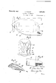
- Figure 1 is a sideelevation of anaeroplane x having another formv ofair intakeginadei-n accordance with this inventionwf: Y.
- I Figure 7 isJan'enlarged section plan View ofr'one oit the air' intakes a'cc'ordingtd 'the form of the' invention illustrated in : Figures Y Figures 8 and 9 are respectively sid'ejelei vations 'and' forward fend. elevations ofpart of the engine'cowling andv air yintake fof" a form slightly ditl'eringto 'thatillustratedlrin Figures 5 to 7. l f
- ⁇ a is an aeroplaneengine contained in 'a covvling t part of the4 propeller being shown at ci d is the super .charging blowen.
- fe isft'he main air intake pipe which is divided intotwo branches e1 which at'the'point oitlieir:emergeVV f enceV from thelcowling arerformed 'i1 , ⁇ 1iri i jectio'ns 'of aerofoil'sliape v@21 as isl illustrated inzj Figures 3" and 4.
- projeetions'ai'e formed with an opening on the underside and across such ⁇ opening areliiied a number l1 fr of horizontal sla-tsoristrip's]c parallel to'eacli each of the projections ther'eis'formeda pres# other, andof'forwagrdly curvingshapfe.: ingl to the shape lofthe@aero-foil?shape f Pil stream. ⁇ Y r Y.
- Another'- form' ofthis invention is illustween the slats'and so into the main air intrated in Figures 5, 6 and 7 where in lieu of formingtheends of the .pipe in aerofoil section;L on tli-eiidsfthereof are -iitted bent-pieces g which in manner shown project yforwardV close to the cowling of the engine in such manner that the air sweeping along such- ⁇ @Wange desde@ Viiii-wiie Said. ineke with themini'inumamount of disturbance.
- carburetterfthat the/velocity ofthel ain ente"1i ing the korifice is approximately the saine as section area t0 the pipeconductingf air to .
- the slats being curved upwards to kform a tapering slaughter between each two of them;
- an air intake member having jan air intake passage way of variable ci'oss section, an orifice presented to the vair being ofvsma-ller Across section area thanftliat ofanyotherlpart'of thek passageway, and being so related incross section area to the pipe conducting air to the that of theexternal air stream.4 Y Y V7.
- an 4air intake niember having an airfintake ypassage ofV variable cross section, and havingfaplu- S0 an; air intake passage of variable 'cross sec;V tionarea and ,with an orifice presented to the air, the cross section of which .is smaller thany thatV of the other partsof the passageway and superchargin 'bl'OWe-r, the 'intake pas'- ,g sage way ott-he inta remember being connect-I ed tothe receiving end of theblower, and the.
Landscapes
- Engineering & Computer Science (AREA)
- Chemical & Material Sciences (AREA)
- Combustion & Propulsion (AREA)
- Aviation & Aerospace Engineering (AREA)
- Cylinder Crankcases Of Internal Combustion Engines (AREA)
Description
March 29, 1932. J. E. ELLOR AIR INTAKE FOR ENGINES RlSheets-Sheet Filed sept. 1o. 1929 March 29, 1932. J. E. ELLoR AIR INTAKE FOR ENGINES 2 Sheets-Sheet 2 Filed Sept. l0. 1929 Patented Mar.V 1932 JAMES EDWINIEIQLOR, OFSERBY, ENGLANQASSIGNOR To noiisfnofcii.niixt'nioi 1 nnnBmEneLsNnf1 'j periencedin/connection with the shape of the Y' am manna non ENGINES locomotive-machines, such as aeroplanes, and
has for itsobject improved means of supplying :the required air tojthe engine, whether for fuel purposes, cooling purposes or orany other .purposes in respect oi' which admitted airis required to `be `above external `atmospheric pressure.: Difficulties ,have been exair intake in engines `ifor vhigh speed loco-4 motive machines, it being found that in some forms ofsintake theeddies caused by the greatvv speed of the stream'ofairunder certain .conditions inhibit or disturb the passage of air Vthrough the' opening andthe main pipe "lead` ing to the engine. Y
Accordfng to "thisy invention lthe' kinetic eiiergyof the air stream is ,utilized'by `forming'the Iinlet of the intake-as the secondstage of a Venturi tube and consists in a forwardly projecting tube or member, provided with a passage way or passage .ways,veach of which presents to the air stream acomparatively restricted orifice, and as it recedes from such orifice expands in cross section area, andiat its inward end merges or opens into a pipeV or passage way leading to the engine.
In order to avoid so far as possible the air resistance commonly called skin friction which would be produced by such a tube or member, I by preference construct the forn wardly projecting tube or member in aerofoil form, that is tosay, so shaped as to oer a minimuinresistance to movement through the air, and to bring about a negative pressure or vacuum above, and a positive pressure below; and in the tube or member so` formed I construct by preference a number of passage Ways, rectangular and tapering in cross section, each such way having its smaller end open to the atmosphere on Vthe 'l under side of the tube or 'member and its larger end merging or opening into the tube or passage way leading to the engine.
Preferably the cross section area of the orifice or oriicespresented tothe atmosphere is so rela-ted to the cross section area ofthe inaiiipip'e or passageway leadin'gftothe-car-e l' burettor, that the velocityf'of V"air venter-ing such orifice ororiices is approximately that ofthe airstream. I l Y ".Prefer'ably the engine should be provided Withjtwo such intakes, one on each side. The effect Vof the arrangement is that the pressure where the rair isbeing delivered to the engine is substantially increased according'to the well knowniprincipleof'theVem turi tubefv H .i i-
The `invention is particularly us'efulfincon-` nection with engines provided Withra "supers charger, no matter Wliicliroftheknowntypes ,of super-,chargers` is` adopted. 2 i
,Three examples of. this inventionareshown in the accompanyingdrawings.f Y engine cowling. i i f u i lFigure 2y is a 'rear elevation of Figure Figures 3 and 4 are'enlarged sideandfrnt elevationsof one ot'the'air intakes illus# tratedinFigures 1 'and 2.
a 'front elevatioii'ofan engine and its eowli'iigl 1 Figure .5 is a Sideelevationand-ingame :is
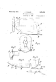
Figure 1 is a sideelevation of anaeroplane x having another formv ofair intakeginadei-n accordance with this inventionwf: Y. I Figure 7isJan'enlarged section plan View ofr'one oit the air' intakes a'cc'ordingtd 'the form of the' invention illustrated in :Figures Y Figures 8 and 9 are respectively sid'ejelei vations 'and' forward fend. elevations ofpart of the engine'cowling andv air yintake fof" a form slightly ditl'eringto 'thatillustratedlrin Figures 5 to 7. l f
`a is an aeroplaneengine contained in 'a covvling t part of the4 propeller being shown at ci d is the super .charging blowen. fe isft'he main air intake pipe which is divided intotwo branches e1 which at'the'point oitlieir:emergeVV f enceV from thelcowling arerformed 'i1 ,`1iri i jectio'ns 'of aerofoil'sliape v@21 as isl illustrated inzjFigures 3" and 4. AThe said projeetions'ai'e formed with an opening on the underside and across such `opening areliiied a number l1 fr of horizontal sla-tsoristrip's]c parallel to'eacli each of the projections ther'eis'formeda pres# other, andof'forwagrdly curvingshapfe.: ingl to the shape lofthe@aero-foil?shape f Pil stream.` Y r Y.
' 5...;In an internal combustion engine an air Ysureoi air underneath it (which further aids Y the Venturi tube constrictor in causing air pressure in the intake'pipe) and-'such air will pass into the narrow opening left bevtake pipe.v Y. Y
Another'- form' ofthis invention :is illustween the slats'and so into the main air intrated in Figures 5, 6 and 7 where in lieu of formingtheends of the .pipe in aerofoil section;L on tli-eiidsfthereof are -iitted bent-pieces g which in manner shown project yforwardV close to the cowling of the engine in such manner that the air sweeping along such-` @Wange desde@ Viiii-wiie Said. ineke with themini'inumamount of disturbance.
`In Figures 8 and 9 the ends of thesaidl air intake in ,lieu` offbeing carried straight through thecowlng are bent forward and .carried for some considerable way inside 'such cowlinggas shown at i andv are tapered as shown ath1 and eventually emerge as plain iush cicular holes V71,2.
.. What I claim is 1. In'ank internal combustion engine anA air-intakeineniberihaving am'ain air intake passage way, av plurality of subsidiary air passage ways each at one end connected to the K.
main passage wayand at the otherhaving an orifice presentedcto-the air, the subsidiary passage ways diminishing in cross section L areal-as theyfrecede from the-main passage way and vthe 'aggregate cross section areas of their orifices beingl less than the cross section area of the main passage way.Vr p f 2; In an internal combustion engine an air intakememberhaving a part in aerofoil v shape,.the-air intake passage being lof'- vari- Orifice being smaller than that of -anyyother able cross section area and having an orifice presented to the-air on the underside ofthe said y.parti and .the cross section area. of the partof the passage way.` 1'
intake member -a partofwhichis of aerofoil shape having its air intake passage way of variable cross section area and having a plurality of orifices presented to the air on'tlie intake member apart of which is of aerofoil s shape having a passageway oi variable crossy section:area, with` aplurality of orifices pre-` sented toatheair onthe underside of the said underside of thesaid vpart the aggregatecross sectionareas of such orifices beingless than theicross sectionarea of anypartof the main passage way. v
4; Inaninternalconibustionlengine an air part, ,such Vorifices being inthe forinoi apv proximately parallel rectangular openings approximately normal` to? the external air intake'.member as claimed e inclaim YNo',l 1et f Vthe said part having anenlarged opening on i the underside, with overlapping Aslats 4fixed acrosssuch opening in parallel relation, and
carburetterfthat the/velocity ofthel ain ente"1i ing the korifice is approximately the saine as section area t0 the pipeconductingf air to .the
`combination of an airl intake member having my. signature.
the slats being curved upwards to kform a tapering orice between each two of them;
6. In an internal combustion lengine an air intake member having jan air intake passage way of variable ci'oss section, an orifice presented to the vair being ofvsma-ller Across section area thanftliat ofanyotherlpart'of thek passageway, and being so related incross section area to the pipe conducting air to the that of theexternal air stream.4 Y Y V7. In an internal combustionv engine an 4air intake niemberhaving an airfintake ypassage ofV variable cross section, and havingfaplu- S0 an; air intake passage of variable 'cross sec;V tionarea and ,with an orifice presented to the air, the cross section of which .is smaller thany thatV of the other partsof the passageway and superchargin 'bl'OWe-r, the 'intake pas'- ,g sage way ott-he inta remember being connect-I ed tothe receiving end of theblower, and the.
`exit' from the blower, tof-the inlet of there-arey buretter; A In testimony whereof I have hereto afiixedv v3... In'ran'internal combustion engine Van air Y
Applications Claiming Priority (1)
| Application Number | Priority Date | Filing Date | Title |
|---|---|---|---|
| GB1851500X | 1928-09-13 |
Publications (1)
| Publication Number | Publication Date |
|---|---|
| US1851500A true US1851500A (en) | 1932-03-29 |
Family
ID=10891971
Family Applications (1)
| Application Number | Title | Priority Date | Filing Date |
|---|---|---|---|
| US391547A Expired - Lifetime US1851500A (en) | 1928-09-13 | 1929-09-10 | Air intake for engines |
Country Status (1)
| Country | Link |
|---|---|
| US (1) | US1851500A (en) |
-
1929
- 1929-09-10 US US391547A patent/US1851500A/en not_active Expired - Lifetime
Similar Documents
| Publication | Publication Date | Title |
|---|---|---|
| US3329377A (en) | Protection for aircraft engines against snow, ice and airborne particles | |
| US2164545A (en) | Airplane | |
| US2636666A (en) | Gas turbine engine with de-icing apparatus | |
| US2600302A (en) | Air cleaning intake for gas turbines and other internal-combustion engines | |
| US2633703A (en) | Multiple tail pipe jet | |
| US2469902A (en) | Aircraft wings having boundary layer control | |
| US1920883A (en) | Engine cooling system | |
| US1799397A (en) | Internal-combustion engine | |
| US1851500A (en) | Air intake for engines | |
| US2421518A (en) | Jet propulsion | |
| US2945641A (en) | Aircraft with wing containing lifting jets | |
| US2388247A (en) | Airplane | |
| US2177642A (en) | Aircraft cowling | |
| US2198229A (en) | Cooling means for aircraft engine exhaust stacks | |
| US2634581A (en) | Separate burner system for deicing the inlets of multiple gas turbine units | |
| US1922469A (en) | Supercharger for carburetors | |
| US2399839A (en) | Flying machine | |
| US1880531A (en) | Air intake and exhaust mechanism of diesel type of engines | |
| US1866663A (en) | Air cleaner and air turbination inductor | |
| US2169243A (en) | Supercharger and cooler arrangement | |
| US2192730A (en) | Exhaust pipe for internal combustion engines of aircraft | |
| US2077708A (en) | Airplane | |
| US2272626A (en) | Cooling arrangement for aircraft engines | |
| US1972190A (en) | Supercharger | |
| US1890708A (en) | Supercharger |