US1851495A - Radio broadcast distribution - Google Patents
Radio broadcast distribution Download PDFInfo
- Publication number
- US1851495A US1851495A US210911A US21091127A US1851495A US 1851495 A US1851495 A US 1851495A US 210911 A US210911 A US 210911A US 21091127 A US21091127 A US 21091127A US 1851495 A US1851495 A US 1851495A
- Authority
- US
- United States
- Prior art keywords
- circuit
- detector
- tuned
- frequency
- circuits
- Prior art date
- Legal status (The legal status is an assumption and is not a legal conclusion. Google has not performed a legal analysis and makes no representation as to the accuracy of the status listed.)
- Expired - Lifetime
Links
- 230000035559 beat frequency Effects 0.000 description 3
- 238000010586 diagram Methods 0.000 description 3
- 239000000543 intermediate Substances 0.000 description 3
- 230000005540 biological transmission Effects 0.000 description 2
- 239000000969 carrier Substances 0.000 description 1
- 230000008878 coupling Effects 0.000 description 1
- 238000010168 coupling process Methods 0.000 description 1
- 238000005859 coupling reaction Methods 0.000 description 1
- 230000001681 protective effect Effects 0.000 description 1
- 230000005236 sound signal Effects 0.000 description 1
Images

Classifications
-
- H—ELECTRICITY
- H04—ELECTRIC COMMUNICATION TECHNIQUE
- H04H—BROADCAST COMMUNICATION
- H04H20/00—Arrangements for broadcast or for distribution combined with broadcast
- H04H20/65—Arrangements characterised by transmission systems for broadcast
- H04H20/76—Wired systems
- H04H20/77—Wired systems using carrier waves
-
- H—ELECTRICITY
- H04—ELECTRIC COMMUNICATION TECHNIQUE
- H04H—BROADCAST COMMUNICATION
- H04H20/00—Arrangements for broadcast or for distribution combined with broadcast
- H04H20/02—Arrangements for relaying broadcast information
-
- H—ELECTRICITY
- H04—ELECTRIC COMMUNICATION TECHNIQUE
- H04H—BROADCAST COMMUNICATION
- H04H20/00—Arrangements for broadcast or for distribution combined with broadcast
- H04H20/65—Arrangements characterised by transmission systems for broadcast
- H04H20/76—Wired systems
- H04H20/84—Wired systems combined with power distribution network
Definitions
- My invention relatesto'radio and radiowire broadcasting, and has for its object the distribution of programs economically and efficiently.
- the application is in the nature of a continuation in part'fof each of my two prior copending applications, Serial No. 746,358, filed October 28, 1924, issued as Patent No. 1,672,372, June 5,1928, 'andjSerial No. 17,546, filed August 1,1925, isued a s Patent N 0. 1,777,690, October 7, 1930.
- the subscriber needs only a single detector, but if radiated on a carrier wave, his instrument must be a double detector, the first detector taking off the long wave and the second detector taking off the audio modulations. In either case the subscriber must have tuned or tunable means for selecting the particular intermediate frequency, and thereby the particular program, he desires.
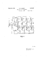
- Fig. 1 is a diagram of a relay station equipped with my invention for receiving and distributing programs on dififerent intermediate or beat wave lengths over wire circuits.
- Fig. 2 is a similar diagram showing the circuits of a heterodyne receiver and its connection to modulating andradiating circuits, for plural transmission of collected'programs on a single carrier wave.
- F ig. 3 is a similar diagram of a subscribers selective receiver for use in the system of Fig. 2.
- Fig. 1 'Referring to Fig.1, 'the'numerals 1,2,3 and i designate four heterodyne receivers, each of the'type shown in Fig. *2, and all, as regards their collecting or input circuits 24:,
- 'the'sv'stem of Fig. 1 works as follows:
- the collector circuits 24 are tuned to receive from four difierent stations, which maybe'near or far.
- the four filter couplers 5, 6, 7 and 8 are fixedly tunedto the four beat frequencies to be employed.
- the four modulated beat waves pass to the amplifiers 9, 10,11 and 12, and so to the tube 20 and the power tubes 21,'fro'rn which all.
- four sets of modulated waves are transmitted through coupler 30 to the circuit 31.
- the subscriber using a tunable detector set of ordinary type, plugged into jack 34, may select the particularfrequency, and thereby Gil the particular program he desires, and may detect off and hear the same.
- a suitable type of instrument for this purpose is indicated in Fig. 39 of Letters Patent 1,635,153 granted to me July 5, 1927.
- each heterodyne receiver collects the carrier waves from the primary stations, reduces the frequency of the same by heterodyning to produce a modulated beat wave of the proper frequency to pass through the filter coupler 27.
- This modulated beat wave is then amplified in the tubes 28 and passed to thecircuit 17 through the coupler 14.
- Gther signals from other primary stations are received on other heterodyne instruments, similar 1n every respect to the one illustrated in Fig. 2, but having their'filter couplers 27 tuned to different frequencies therefrom. These other instruments are connected through the couplings 13, 15 and 16 to the circuit 17, the arrangement up to this point being similar in every respect to that shown in Fig. 1.
- the circuit 17 is connected to the input or grid and filament terminals of the modulator tube 20 whose plate circuit is connected up in a well known manner to the circuits of the oscillator tube 19, forming. part'of the transmission circuit 23 connected to the radiator 22. Any other desired and suitable modulator and transmitter circuit may be substituted without departing from the invention.
- the beat waves from the four heterodyne instruments, each modulated with its own program, from its own station, are thus all imposed by plural modulation through the tube 20 on the carrier wave produced by the tube 19 and radiated from the circuit 22.
- the subscriber For selecting and receiving these signals the subscriber must be provided with a first and second detector, with means to tune the first detector circuit to the frequency of the carrier wave radiated from antenna 22 in Fig. 2; and means to tune the second detector circuit at will to anyone of the four frequencies of the heat waves modulated on said carrier. By thus tuning anyone of the beat waves can be selected, and the second detector will then take off the audio signal waves which can be rendered audible in a suitable telephonic instrument.
- I may make use of the receiving circuits illustrated and described in my prior copending application Serial No. 31,928. In Fig.
- the first detector and its tunable input circuit connected to the antenna and its plate circuit extending to four tuned filter couplers each adapted to receive one of the four interme diate or heat wave frequencies transmitted from the apparatus of Fig. 2.
- a second deconnection with the second detector is shown.
- each filter coupler both with ithe plate circuit of the first detector and with the grid circuitof the second detector.
- a separate grid leak and condenser is provided with each filter coupler to be use il lin ills enables the subscriber to receive selectively by double demodulation anyone of the four original signals or programs relayed from the station in Fig. 2, by merely throwing a switch.
- the first detector is indicated at 40,.thesecond detector at 41, the filter couplers at 42, 43, 44 and 45, and the switches for selecting programs at 46, 47,48 and 49.
- the key-set becomes suitable for use in receiving the signals sent by wire from the relay of Fig. 1.
- the wire ends 50,.51'in Fi 3 at points was would be connected across the circuit .31 of Fig. 1 in place of jack 34; or the wires 5051 may terminate in a plug to fit jack 34.
- Apparatus for multiplex relaying of radiosi nals com risin a luralit of se arate frequency changing receivers each including a separate tuned collector circuit, an oscillator and a tuned first detector circuit. the frequency of said oscillator being adj ustable to produce, a constant frequency beat from high, frequency waves received a. common collecting circuit, a separate filter coupler tuned to the beat frequency of its own receiver, and connecting each receiver with said collecting circuit, a high frequency gen erating, modulating and radiating apparatus connected with said collecting circuit, whereby a plurality of separately received signals may be relayed as multiple modulations upon a single carrier wave.
- Apparatus for multiplex relaying of radio signals which comprises a plurality of heterodyning receiving units each having a tuned collector circuit a first detector tube in a separately tuned circuit and an oscillator tube in a separately tuned circuitand a filter coupler permanently tuned to the beat frequency of its own receiver, a collecting circuit common to all of said receivers, transmitting links connecting the several filter couplers to said collecting circuit, a modulator tube having its input circuit connected to said collecting circuit and its output or plate circuit connected to a suitable transmitterand radiator, together with suitable sources of current supply.
Landscapes
- Engineering & Computer Science (AREA)
- Signal Processing (AREA)
- Mobile Radio Communication Systems (AREA)
Description
March 29, 1932.
E. E. CLEMENT RADIO BROADCAST DISTRIBUTION Filed Aug. 5. 1927 2 Sheets-Sheet l #5 rev? 00 r/ve 4W0 175756708 OSCILLFT Z March 29, 1932.
E. E. CLEMENT RADIO BROADCAST DISTRIBUTION Filed Aug. 5. 1927 2 Sheets-Sheet 2 Patented Mar. 29, 1932 UNH'EE STAT-YES spare:
EDWARD E. CLEMENT, OF WASHINGTON, DISTRICT OF CGLUMBIA, ASSIGNOR TC EDWARD F. COLLADAY, OF 'W-ASHINGTON, ID'ISYIBJK'JT OF- COLUMBIA I RADIO .YBROADCAST. msTnIBumIoN Application 'filedAugust 5, 1927. seiiaim; 210311.
My invention relatesto'radio and radiowire broadcasting, and has for its object the distribution of programs economically and efficiently. The application is in the nature of a continuation in part'fof each of my two prior copending applications, Serial No. 746,358, filed October 28, 1924, issued as Patent No. 1,672,372, June 5,1928, 'andjSerial No. 17,546, filed August 1,1925, isued a s Patent N 0. 1,777,690, October 7, 1930. I attain either over wires or as plural modulations on a second high frequency carrier wave. If distributed by wire, the subscriber needs only a single detector, but if radiated on a carrier wave, his instrument must be a double detector, the first detector taking off the long wave and the second detector taking off the audio modulations. In either case the subscriber must have tuned or tunable means for selecting the particular intermediate frequency, and thereby the particular program, he desires.
My invention is illustrated in the accompanying drawings, in which i Fig. 1 is a diagram of a relay station equipped with my invention for receiving and distributing programs on dififerent intermediate or beat wave lengths over wire circuits.
Fig. 2 is a similar diagram showing the circuits of a heterodyne receiver and its connection to modulating andradiating circuits, for plural transmission of collected'programs on a single carrier wave.
F ig. 3 is a similar diagram of a subscribers selective receiver for use in the system of Fig. 2.
'Referring to Fig.1, 'the'numerals 1,2,3 and i designate four heterodyne receivers, each of the'type shown in Fig. *2, and all, as regards their collecting or input circuits 24:,
tuned to diifer'en't frequencies and receiving 1:
andtheamplifiersas 9, 10,11 and 12. These amplifiers are coupled through coils '13, 14, 15 and 16, to a common circuit'17 ,which constitutesthe input or igrid -'circuit ofa collecting or amplifyingtube 20, whose platecircuit is coupled't'o' asuit'ableset ofpowertubes 21, whose output" terminals in turn are coupled at 30 to thew-ire circuit 31, symbolizing a line or network'of electric light or otherwires. 32 is a condenser of low capacity in said circuit to keep low frequency current ofi the radio circuits; and 35 indicates the usual protective devices, fuses, etc. to keep the high frequency waves ofi" the electric light mains and also to afford additional protection from any surging or disturbance in the mains. The power supply is indicated at 36. 3 1 shows a jack, by'm'ean's of whichthe subscribers re ceiving set may be connected across the circuit 31, also through low capacity condensers.
In operation, 'the'sv'stem of Fig. 1 works as follows: The collector circuits 24 are tuned to receive from four difierent stations, which maybe'near or far. The four filter couplers 5, 6, 7 and 8 are fixedly tunedto the four beat frequencies to be employed. By tuning the oscillating circuits to h'eterodyne with the incoming carrier waves, the four modulated beat waves pass to the amplifiers 9, 10,11 and 12, and so to the tube 20 and the power tubes 21,'fro'rn which all. four sets of modulated waves are transmitted through coupler 30 to the circuit 31.
The subscriber, using a tunable detector set of ordinary type, plugged into jack 34, may select the particularfrequency, and thereby Gil the particular program he desires, and may detect off and hear the same. A suitable type of instrument for this purpose is indicated in Fig. 39 of Letters Patent 1,635,153 granted to me July 5, 1927.
The system of Fig. 2 works as follows: each heterodyne receiver collects the carrier waves from the primary stations, reduces the frequency of the same by heterodyning to produce a modulated beat wave of the proper frequency to pass through the filter coupler 27. This modulated beat wave is then amplified in the tubes 28 and passed to thecircuit 17 through the coupler 14. Gther signals from other primary stations are received on other heterodyne instruments, similar 1n every respect to the one illustrated in Fig. 2, but having their'filter couplers 27 tuned to different frequencies therefrom. These other instruments are connected through the couplings 13, 15 and 16 to the circuit 17, the arrangement up to this point being similar in every respect to that shown in Fig. 1. In Fig. 2 however, it is intended to reradiate the signal modulated carriers received, as plural modulations on another single carrienwave. Hence the circuit 17 is connected to the input or grid and filament terminals of the modulator tube 20 whose plate circuit is connected up in a well known manner to the circuits of the oscillator tube 19, forming. part'of the transmission circuit 23 connected to the radiator 22. Any other desired and suitable modulator and transmitter circuit may be substituted without departing from the invention. The beat waves from the four heterodyne instruments, each modulated with its own program, from its own station, are thus all imposed by plural modulation through the tube 20 on the carrier wave produced by the tube 19 and radiated from the circuit 22. For selecting and receiving these signals the subscriber must be provided with a first and second detector, with means to tune the first detector circuit to the frequency of the carrier wave radiated from antenna 22 in Fig. 2; and means to tune the second detector circuit at will to anyone of the four frequencies of the heat waves modulated on said carrier. By thus tuning anyone of the beat waves can be selected, and the second detector will then take off the audio signal waves which can be rendered audible in a suitable telephonic instrument. As an alternative and in order to avoid tuning of the secondary or second selector circuits, I may make use of the receiving circuits illustrated and described in my prior copending application Serial No. 31,928. In Fig. 3 of this application, I have shown the first detector and its tunable input circuit connected to the antenna and its plate circuit extending to four tuned filter couplers each adapted to receive one of the four interme diate or heat wave frequencies transmitted from the apparatus of Fig. 2. A second deconnection with the second detector.
apparatus while simple is very effective, and.
desired one of said filter couplers, both with ithe plate circuit of the first detector and with the grid circuitof the second detector. It may be noted that in the figure referred to, a separate grid leak and condenser is provided with each filter coupler to be use il lin ills enables the subscriber to receive selectively by double demodulation anyone of the four original signals or programs relayed from the station in Fig. 2, by merely throwing a switch. In Fig. 3, the first detector is indicated at 40,.thesecond detector at 41, the filter couplers at 42, 43, 44 and 45, and the switches for selecting programs at 46, 47,48 and 49. It should be noted that by simply omitting the first detector-40, the key-set becomes suitable for use in receiving the signals sent by wire from the relay of Fig. 1. In such case the wire ends 50,.51'in Fi 3 at points was would be connected across the circuit .31 of Fig. 1 in place of jack 34; or the wires 5051 may terminate in a plug to fit jack 34.
What I claim is:
1. Apparatus for multiplex relaying of radiosi nals com risin a luralit of se arate frequency changing receivers, each including a separate tuned collector circuit, an oscillator and a tuned first detector circuit. the frequency of said oscillator being adj ustable to produce, a constant frequency beat from high, frequency waves received a. common collecting circuit, a separate filter coupler tuned to the beat frequency of its own receiver, and connecting each receiver with said collecting circuit, a high frequency gen erating, modulating and radiating apparatus connected with said collecting circuit, whereby a plurality of separately received signals may be relayed as multiple modulations upon a single carrier wave.
2. Apparatus for multiplex relaying of radio signals which comprises a plurality of heterodyning receiving units each having a tuned collector circuit a first detector tube in a separately tuned circuit and an oscillator tube in a separately tuned circuitand a filter coupler permanently tuned to the beat frequency of its own receiver, a collecting circuit common to all of said receivers, transmitting links connecting the several filter couplers to said collecting circuit, a modulator tube having its input circuit connected to said collecting circuit and its output or plate circuit connected to a suitable transmitterand radiator, together with suitable sources of current supply.
In testimony whereof I hereunto afiix my signature.
EDWARD E. CLEMENT.
Priority Applications (1)
| Application Number | Priority Date | Filing Date | Title |
|---|---|---|---|
| US210911A US1851495A (en) | 1927-08-05 | 1927-08-05 | Radio broadcast distribution |
Applications Claiming Priority (1)
| Application Number | Priority Date | Filing Date | Title |
|---|---|---|---|
| US210911A US1851495A (en) | 1927-08-05 | 1927-08-05 | Radio broadcast distribution |
Publications (1)
| Publication Number | Publication Date |
|---|---|
| US1851495A true US1851495A (en) | 1932-03-29 |
Family
ID=22784813
Family Applications (1)
| Application Number | Title | Priority Date | Filing Date |
|---|---|---|---|
| US210911A Expired - Lifetime US1851495A (en) | 1927-08-05 | 1927-08-05 | Radio broadcast distribution |
Country Status (1)
| Country | Link |
|---|---|
| US (1) | US1851495A (en) |
Cited By (1)
| Publication number | Priority date | Publication date | Assignee | Title |
|---|---|---|---|---|
| US2525679A (en) * | 1948-02-06 | 1950-10-10 | Marcel Wallace | Multiband panoramic receiving system |
-
1927
- 1927-08-05 US US210911A patent/US1851495A/en not_active Expired - Lifetime
Cited By (1)
| Publication number | Priority date | Publication date | Assignee | Title |
|---|---|---|---|---|
| US2525679A (en) * | 1948-02-06 | 1950-10-10 | Marcel Wallace | Multiband panoramic receiving system |
Similar Documents
| Publication | Publication Date | Title |
|---|---|---|
| US2317547A (en) | Communication system | |
| US2028212A (en) | Radio transmitting system | |
| US2250532A (en) | Radio relaying system | |
| US2229043A (en) | Radio reception system | |
| US1851495A (en) | Radio broadcast distribution | |
| US1754878A (en) | Traffic-control system for radio broadcast distribution | |
| US1754876A (en) | Regional system of radio broadcast distribution | |
| KR19990081412A (en) | Optical conversion repeater and optical signal transmission method using single optical cable | |
| KR100984838B1 (en) | Wireless signal distribution device and receiving system comprising the device | |
| US2545511A (en) | Radio communication system | |
| US2345951A (en) | Radio relay control system | |
| US2154923A (en) | Signaling system | |
| USRE17163E (en) | District | |
| US2509716A (en) | Arrangement for secret radio telephony | |
| US3838343A (en) | Broadband cable communications system | |
| US2153052A (en) | Radio broadcasting system | |
| US1577106A (en) | Radio distributing system | |
| US1799976A (en) | Radio system | |
| US2188508A (en) | Multiple distribution system | |
| US2819344A (en) | Frequency division multiplexing | |
| US1904544A (en) | Carrier wave signaling system | |
| US2895009A (en) | Channeling system for frequency spectrum transmission | |
| US1748279A (en) | Wave-transformation system of radio broadcast distribution | |
| US1815833A (en) | Subdivided service system of radio broadcast distribution | |
| US1869356A (en) | Wired broadcast distributing system |