US1851489A - Floor jack - Google Patents
Floor jack Download PDFInfo
- Publication number
- US1851489A US1851489A US435182A US43518230A US1851489A US 1851489 A US1851489 A US 1851489A US 435182 A US435182 A US 435182A US 43518230 A US43518230 A US 43518230A US 1851489 A US1851489 A US 1851489A
- Authority
- US
- United States
- Prior art keywords
- cylinder
- cam
- shoe
- cylinders
- handle
- Prior art date
- Legal status (The legal status is an assumption and is not a legal conclusion. Google has not performed a legal analysis and makes no representation as to the accuracy of the status listed.)
- Expired - Lifetime
Links
- 238000004873 anchoring Methods 0.000 description 3
- 238000009408 flooring Methods 0.000 description 3
- BPXVHIRIPLPOPT-UHFFFAOYSA-N 1,3,5-tris(2-hydroxyethyl)-1,3,5-triazinane-2,4,6-trione Chemical compound OCCN1C(=O)N(CCO)C(=O)N(CCO)C1=O BPXVHIRIPLPOPT-UHFFFAOYSA-N 0.000 description 1
- 101150000595 CLMP gene Proteins 0.000 description 1
- 101100382322 Drosophila melanogaster Acam gene Proteins 0.000 description 1
- 238000010276 construction Methods 0.000 description 1
- 230000000994 depressogenic effect Effects 0.000 description 1
- 210000002105 tongue Anatomy 0.000 description 1
- 235000014101 wine Nutrition 0.000 description 1
Images
Classifications
-
- E—FIXED CONSTRUCTIONS
- E04—BUILDING
- E04F—FINISHING WORK ON BUILDINGS, e.g. STAIRS, FLOORS
- E04F21/00—Implements for finishing work on buildings
- E04F21/20—Implements for finishing work on buildings for laying flooring
- E04F21/22—Implements for finishing work on buildings for laying flooring of single elements, e.g. flooring cramps ; flexible webs
Definitions
- Another object ofthe invention is: to "so constructand arrange the parts that when the cam is moved to projecting position it willjlocl; the parts in-this'p0sitioi1.
- This invention also consists in'cer'tain other "features of constructionandin the combinationand ⁇ arrangement of the "several parts, tobe hereinafter fully described, illustrated in theecconipanying drawings and specifically pointed out in”- the appended In describing theinvefition'in detail; reference' will be had to the accompanying d r'awingswherein like characters-denote like or corresponding part's'throughout the several views, and in which 1 g Figure-1 is a sectional view'showing the device in use and before the cam is moved to projecting position.
- Figure 2 is a similar View, but showing the cam in position locking the shoe carrying cylinder in projecting position.
- Figure 3 is a top plan view of Figure 2.
- FIG. 7 is a section on line 77 of Fig- Figure 5 is an end View showing the points ena's-fepen and their outer ends closed and the 'pylinder 1 is formed with thepointsjor pr0 ect1ons 3 at its o-uterrend whieli are ad'apt-v edtobe driven into a Seastor other supporting memb r -A.&The t0 of this cylindeif outer end, is formed with aflthickened" p 4 am so that it can be struck byiahamnierfiorthe like to cause the so formed that .it Inlay he used with i boards. V
- tubular member can be slipped overthe handleso as to provide-greater leverage for operating the cam.
- the foot When used on floor boards, the foot.
- a on the shaftand having a vpair of active faces 'anda handle connected .witlrthe cam and passing through slots-in the cylinders wherebyby moving the handleinv a certain direction, oneof ithe facesof vthe-Team wines handle may be depressed by the" engaginga strip of flooring, acam having angularly disposed faces carried by said cyl'-' inders, tensionmeans between the inner cylinder and the cam, and a handle for adjust- 'sion means, whereby the positioning of the ing the position of the cam to alternately engage the faces of the cam with said tenhandle inone, position will bring one of the faces into engagement with the tension means for holding theinner cylinder pro- .jeotedlrelative' to the outer cylinder.
- a floor jack comprising inner and outer cylinders, anchoring means for the outer cylv a. I .7 inder,.a shoe on the inner cylinder to engage-
- I have provided a strip of flooring, a cam pivotally and slidably connected to the cylinders andhaving angularly disposed faces, tension means beto alternately engage the faceslof the cam j-with said tension means whereby the posibringione of the fa cesintoengagement with the tension means for holding .theinner cyltioning of :the handle in one position will inder projected relative to the'outergcylindenfl v 5.
- a floor jack comprising inner and outer 7 cylinder, a shoe on the inner cylinder to en -gage astrip of flooring, a campivotally and ingangularlydisposed-faces, a follower slid- .jc ylinders, an anchoring means :on the outer slidably. connectedlto thecylinders and heart-i 5 able in the inner cylinder to be engaged by the cam, tension means between the inner cylinder vand'the follower, and the handle handle in one position will bring one of the gag ancr exert!
Landscapes
- Engineering & Computer Science (AREA)
- Architecture (AREA)
- Civil Engineering (AREA)
- Structural Engineering (AREA)
- Footwear And Its Accessory, Manufacturing Method And Apparatuses (AREA)
Description
R. BROOK FLodR JACK March 29, 1932.
Filed March 12. 1930 2 Sheets-Sheet INVENTOR ATTORNEY March 29, 1932gf R BROOK 1,851,489
FLOOR JACK Filed March 12, 1930 2 Sheets-Shee 2 57' 0 0 INVENTOR ATTOR NEY Patented Mar. 29, 1932' ,nne nntn isnoemo'r vmcouvnmmnicrlsnz COLUMBIA, CANADA f 1 1 4 01;v JACK {sani ati nfiledmaiih 12, 930. Seria1No.435,18 2. I g
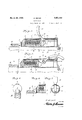
i This invention relatesto a jackfor pressingboards' or the likeinto place, the device beingmainly designed' for "use with: floor boards; ceiling hoards, ete.; thfe=general object 5 of the invention being to 'providefapairfof telescopic cylinders, one cylinder' having points at its outer end adapted to bedriven into a supporting member and the otherxhaving a shoe for engaging the nienihertoihe pressedinto place, with a manually operated cam for causinga spring to=press the shoe carrying cylinder forwardly toexert pres .sure on the board. 5 1 7 Another object ofthe invention is: to "so constructand arrange the parts that when the cam is moved to projecting position it willjlocl; the parts in-this'p0sitioi1. v This invention also consists in'cer'tain other "features of constructionandin the combinationand {arrangement of the "several parts, tobe hereinafter fully described, illustrated in theecconipanying drawings and specifically pointed out in"- the appended In describing theinvefition'in detail; reference' will be had to the accompanying d r'awingswherein like characters-denote like or corresponding part's'throughout the several views, and in which 1 g Figure-1 is a sectional view'showing the device in use and before the cam is moved to projecting position.
Figure 2 is a similar View, but showing the cam in position locking the shoe carrying cylinder in projecting position.
Figure 3 is a top plan view of Figure 2.
I Figure 4: is a section on line 4. lof Figure 2.
fragmentary view similar to 7 is a section on line 77 of Fig- Figure 5 is an end View showing the points ena's-fepen and their outer ends closed and the 'pylinder 1 is formed with thepointsjor pr0 ect1ons 3 at its o-uterrend whieli are ad'apt-v edtobe driven into a joistor other supporting memb r -A.&The t0 of this cylindeif outer end, is formed with aflthickened" p 4 am so that it can be struck byiahamnierfiorthe like to cause the so formed that .it Inlay he used with i boards. V
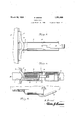
j' t edges as j l, a age a n having stra' tongues; pp a by An opening sis-formed at the center of the shoe, said. opening extending thr'oughthe front edge of the shoe and, this vopening per. niits the board tohe minder otherwise fast} ened place while'it'is being pressed. the "shoe. J The shoe is] of} elongated form; as shown seas to engage. a 'considerable part of the boardfand smashes cents formedjwith thickenedportions, if desired; so that it can fbestru'ck by a hammer or the'like, f ,cup-shaped piston Sfis arranged inthe inner cylinder2 and a spring" 9is, located in the cylinder and he'ars against the front inner I endthei e i and against thepistofi; V l "iA sha 1310 has itsends fitting i fh'oles .in tlie 01:1ter cylinder and saidfs'haft; passes 7 through elongated slotsflll in the inner cylinder; the shaft carrying a: c-am 12which' is '85 formed with a curved handle13which passes through sIOt sQl Lifor-inedin the ppei partsof thecylinders-ff V p H y When the handle isin raised position, a fiat fedgefof 'thecam willenfgag'e the piston, as
'ishdwninFi ui e 1, but when the hai'idle is] a swung downwardly and'rearwardly, the nose ofi'thecani will engage the. piston and this force the same forwardlyso asto contract the spring and causcisaid spring tdprojectfthe cylinder 2 cause the shoe to exert pressure against the board which'it'engages. ,The partsare" so arranged and constructed that when the handle is de 'ji-"essed, theic'am will loek thepartsin projected position; as shown atits 55 points to penetrate t esupmed the outer end ofthefco in'Figure 2, so thatit is not necessary tohold V the handle indepressed position and thus both v or it may be used onceiling boards, as shown in Figure 8, and,.of course, it can beused on side boards, When used on ceiling boards, a-
tubular member can be slipped overthe handleso as to provide-greater leverage for operating the cam. When used on floor boards, the foot.
a simpledevice for pressing one board against another and for lioldingth nb r position while it is being n d I a, I
Itis ;thoughtfrom the foregoing 7 tion' that theadvantages and novel features'of the invention willbe readily apparent. I I I wItis to be understood that changes maybe made in the construction and in the combination-and arrangement of the several par ts,
' provided thatsuch 'changesfall within'the scope of theappended claims.
end of onecylinder, pointed proj ections atjthe outer end of the other cylinder, spring means in the inner cylinder, a transverse shaft piv- I I otallyand slidably connected tothe cylinders,
a on the shaftand having a vpair of active faces, 'anda handle connected .witlrthe cam and passing through slots-in the cylinders wherebyby moving the handleinv a certain direction, oneof ithe facesof vthe-Team wines handle may be depressed by the" engaginga strip of flooring, acam having angularly disposed faces carried by said cyl'-' inders, tensionmeans between the inner cylinder and the cam, and a handle for adjust- 'sion means, whereby the positioning of the ing the position of the cam to alternately engage the faces of the cam with said tenhandle inone, position will bring one of the faces into engagement with the tension means for holding theinner cylinder pro- .jeotedlrelative' to the outer cylinder.
i. A floor jack comprising inner and outer cylinders, anchoring means for the outer cylv a. I .7 inder,.a shoe on the inner cylinder to engage- Thusit will be seen that I have provided a strip of flooring, a cam pivotally and slidably connected to the cylinders andhaving angularly disposed faces, tension means beto alternately engage the faceslof the cam j-with said tension means whereby the posibringione of the fa cesintoengagement with the tension means for holding .theinner cyltioning of :the handle in one position will inder projected relative to the'outergcylindenfl v 5. v A floor jack comprising inner and outer 7 cylinder, a shoe on the inner cylinder to en -gage astrip of flooring, a campivotally and ingangularlydisposed-faces, a follower slid- .jc ylinders, an anchoring means :on the outer slidably. connectedlto thecylinders and hart-i 5 able in the inner cylinder to be engaged by the cam, tension means between the inner cylinder vand'the follower, and the handle handle in one position will bring one of the gag ancr exert! pressure upon the spring ing out through saidouter edge, downwardly extending pointed projections at theouter inder having longitudinally extending slots thereinand both cylinders having longitua shaft passing transversely through the cylinderswith itsends oarriedby the outer 1 cylinder and said shaft passing through the holding the inner cylinder to the outer cylinder. I V a. 7 v 1 In testimony whereof I afiix mysignaturer ,ner' cylinder, said Tshoehaving agroove in its outeredge and open ng at ts center openendof ,the outer cylinder, said inner cyldillally extending slots i n their upper parts,
k first mentioned slots in they inner cylinder,ia.
cam on the shaft, ahandle,connectedfwith A I ,the cam and passing through the upper a I slots in the cylinders, a'piston in the inner I v cylinder engaged by the, cam and a. spring 3. A floor jack'comprising inner and outer cylinders-a shoe on the other cylinder-and in the'inn er cylinder'bearing against the piston andthe frontend of the inner cylinder.
faces into engagement with the follower for .1; E IN L -BROO I cylinders, anchoring; means for ,one of the i p rejected {relative i for adjusting thepositionof the cam to alter- 1 .nately engage the faces of said cam-Withthe follower', and whereby the positioning of the i
Priority Applications (1)
| Application Number | Priority Date | Filing Date | Title |
|---|---|---|---|
| US435182A US1851489A (en) | 1930-03-12 | 1930-03-12 | Floor jack |
Applications Claiming Priority (1)
| Application Number | Priority Date | Filing Date | Title |
|---|---|---|---|
| US435182A US1851489A (en) | 1930-03-12 | 1930-03-12 | Floor jack |
Publications (1)
| Publication Number | Publication Date |
|---|---|
| US1851489A true US1851489A (en) | 1932-03-29 |
Family
ID=23727355
Family Applications (1)
| Application Number | Title | Priority Date | Filing Date |
|---|---|---|---|
| US435182A Expired - Lifetime US1851489A (en) | 1930-03-12 | 1930-03-12 | Floor jack |
Country Status (1)
| Country | Link |
|---|---|
| US (1) | US1851489A (en) |
Cited By (9)
| Publication number | Priority date | Publication date | Assignee | Title |
|---|---|---|---|---|
| US2470396A (en) * | 1944-11-14 | 1949-05-17 | Joseph D Guerette | Spur shore |
| US2589404A (en) * | 1950-02-06 | 1952-03-18 | Leo H Lab | Flooring jack |
| US2717144A (en) * | 1951-11-13 | 1955-09-06 | Labuza Walter | Device for setting planking and sheathing |
| US2743902A (en) * | 1952-01-09 | 1956-05-01 | Reese W Porter | Tool for positioning matched planking |
| US2866623A (en) * | 1954-01-18 | 1958-12-30 | Sr Lawrence S Holmboe | Shore jack |
| US3022979A (en) * | 1960-03-28 | 1962-02-27 | Edwin A Dahlke | Carpet stretcher |
| US4720222A (en) * | 1986-08-08 | 1988-01-19 | Nagy Neil F | Restraining bar for pickup trucks |
| EP0790372A1 (en) * | 1996-02-15 | 1997-08-20 | HEBRU-Gardinenland Brunnemer GmbH | Method and apparatus for laying floor coverings |
| EP1270844A1 (en) * | 2001-06-21 | 2003-01-02 | Anders Sandnes | Pressing tool for pressing together floorboards, parquet and similar |
-
1930
- 1930-03-12 US US435182A patent/US1851489A/en not_active Expired - Lifetime
Cited By (9)
| Publication number | Priority date | Publication date | Assignee | Title |
|---|---|---|---|---|
| US2470396A (en) * | 1944-11-14 | 1949-05-17 | Joseph D Guerette | Spur shore |
| US2589404A (en) * | 1950-02-06 | 1952-03-18 | Leo H Lab | Flooring jack |
| US2717144A (en) * | 1951-11-13 | 1955-09-06 | Labuza Walter | Device for setting planking and sheathing |
| US2743902A (en) * | 1952-01-09 | 1956-05-01 | Reese W Porter | Tool for positioning matched planking |
| US2866623A (en) * | 1954-01-18 | 1958-12-30 | Sr Lawrence S Holmboe | Shore jack |
| US3022979A (en) * | 1960-03-28 | 1962-02-27 | Edwin A Dahlke | Carpet stretcher |
| US4720222A (en) * | 1986-08-08 | 1988-01-19 | Nagy Neil F | Restraining bar for pickup trucks |
| EP0790372A1 (en) * | 1996-02-15 | 1997-08-20 | HEBRU-Gardinenland Brunnemer GmbH | Method and apparatus for laying floor coverings |
| EP1270844A1 (en) * | 2001-06-21 | 2003-01-02 | Anders Sandnes | Pressing tool for pressing together floorboards, parquet and similar |
Similar Documents
| Publication | Publication Date | Title |
|---|---|---|
| US1851489A (en) | Floor jack | |
| USD921934S1 (en) | Slab comprising particulate mineral mixture | |
| GB1470593A (en) | Nail extractor | |
| EP0892413A3 (en) | Push button | |
| US1000859A (en) | Combined board-set and nail-driver. | |
| US909469A (en) | Bench-clamp. | |
| EP1152080A3 (en) | Textile material and method for its production | |
| EP0802660A3 (en) | Battery housing for portable telephones | |
| US1098442A (en) | Embroidery-hoop. | |
| US755384A (en) | Clamping device for glue-presses. | |
| US1874128A (en) | Jack | |
| US300731A (en) | Steeeotype plates in the foem | |
| US358673A (en) | Boom for sailing-yachts | |
| US1485863A (en) | Spike puller | |
| US311769A (en) | Device for removing cross-heads | |
| US805360A (en) | Riveting attachment for power-presses. | |
| US11759934B2 (en) | Hammer with linearly adjustable claw | |
| US1580348A (en) | Screw jack | |
| US168649A (en) | Improvement in wood-splitters | |
| US833553A (en) | Attachment for printing-presses. | |
| US1572325A (en) | Piston | |
| US1877363A (en) | Adjustable waste receiver | |
| US413833A (en) | Wire-stretcher | |
| US1483002A (en) | Lifting jack | |
| US1684514A (en) | Hammer |