US1851488A - Elevator signaling system - Google Patents
Elevator signaling system Download PDFInfo
- Publication number
- US1851488A US1851488A US585624A US58562422A US1851488A US 1851488 A US1851488 A US 1851488A US 585624 A US585624 A US 585624A US 58562422 A US58562422 A US 58562422A US 1851488 A US1851488 A US 1851488A
- Authority
- US
- United States
- Prior art keywords
- car
- cars
- signal
- circuit
- landing
- Prior art date
- Legal status (The legal status is an assumption and is not a legal conclusion. Google has not performed a legal analysis and makes no representation as to the accuracy of the status listed.)
- Expired - Lifetime
Links
- 230000011664 signaling Effects 0.000 title description 13
- 238000010276 construction Methods 0.000 description 8
- 238000010586 diagram Methods 0.000 description 6
- 230000000694 effects Effects 0.000 description 6
- 230000033001 locomotion Effects 0.000 description 4
- 238000009434 installation Methods 0.000 description 2
- 230000004048 modification Effects 0.000 description 2
- 238000012986 modification Methods 0.000 description 2
- 238000004804 winding Methods 0.000 description 2
- 241001246312 Otis Species 0.000 description 1
- 230000002730 additional effect Effects 0.000 description 1
- 238000013459 approach Methods 0.000 description 1
- 238000009435 building construction Methods 0.000 description 1
- 238000004891 communication Methods 0.000 description 1
- 230000003111 delayed effect Effects 0.000 description 1
- 210000005069 ears Anatomy 0.000 description 1
- 238000000034 method Methods 0.000 description 1
Images

Classifications
-
- B—PERFORMING OPERATIONS; TRANSPORTING
- B66—HOISTING; LIFTING; HAULING
- B66B—ELEVATORS; ESCALATORS OR MOVING WALKWAYS
- B66B3/00—Applications of devices for indicating or signalling operating conditions of elevators
Definitions
- This invention is an elevator signaling system of the character whereby a passenger at a floor may signal Operators of a bank of elevator cars his intention of entering any one of the cars at the particular floor on which he may be.
- the object of the invention is to provide a simple, economical and highly eflicient system, whereby the pressure of one or more buttons at any particular floor or in any other part of the building will effect the giving of a signal in only one car, namely, the car which is going in the particular direction in which the passenger desires to go and which is the nearest to the particular floor on which the button has been pressed.
- the system of this invention is not only unusually economical to install but is also economical in its operation.
- I mount in any suitable position in the building, such as in the basement, in the shaft, on the overhead or elsewhere, a plurality of magnets.
- Suflicient magnets are provided so that for each car there will be an up magnet and a down magnet for each floor.
- an electric circuit including a source of electrical supply and also including one or more passengers push buttons which the passenger may actuate when he desires to signal the car operator.
- the system of this invention is particularly adapted for the giving of delayed signals and, accordingly, said electric circuit also includes a switch adapted to be automatically closed v as the car approaches the signaling zone of the particular push button included in said circuit.
- the magnet may be energized.
- an armature of novel and efficient construction adapted for the actuation of automatic switch mechanism, which serves not only to effect the maintaining of a signal in the car, as well as other signals which may be desired. but also operates to preclude the giving of signals associated with any other car until the circuit in question has been restored in any suitable manner or the signal is which it is desired to govern under the same conditions.
- Figure 1 is a diagrammatic view illustrating one of the magnets, the associated armature and cooperating switch member together with the wiring diagram of one-car for one direction; r
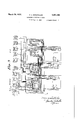
- Figure 2 shows a plan view of the mechanism shown in Figure 1 with a wiring diagram for one floor and one direction for two cars;
- Figure 3 shows the present invention as associated with an old and well known type of elevator installation.
- Elevator signaling systems usually embody an up signaling system and a down signaling system, which usually have common parts or elements.
- the up system is usually referred to in the art as the up section, while the down tion, but that described is a source of electrical energy and 3 a magnet positioned at any desirable location.
- Fig ure 2 of the drawings the magnets of one floor section for two cars are illustrated, although, in practice, any number of cars may be signaled by this invention and the showing is not to be understood as restricted.
- the car lamp or annunciator 4 of all of the cars has a wiring connection 6, which includes the bell 5, while a furtherwiring connection 7 leads from each signal 4 to a selective switch 8, which, when closed, places the annunciator 4' in communication with the winding of the magnet 3 of the corresponding car through a wire 9.
- the frame 14 is made substantially L-shaped.
- the switch element 12 being mounted on a horizontal portion of the frame and the several magnets 3 being mounted on the vertical portion thereof, so that a rigid construction will result.
- the switch element 12 is adapted to engage with all of the contacts 11, this engagement being, in the instance shown, in the form of leaf spring contacts 15 carried by the element 12, and said contacts Hand 15 are normally maintained in engagement in any suitable manner.
- the axis of the pivots 13 is so positioned that the v switch 12 will normally gravitate into engagement with the contacts 11, although in practice a tension spring may be employed to effect such engagement.
- I preferably employ a push button of the character which will remain closed after operation until it is subsequently reset by means forming no part of this invention.
- magnets 3 may be included in circuits other than the push button circuits but adapted to be closed through operation of the push button. This phase of the construction may be varied in many ways, the essential feature being that when a push button is operated, a circuit including magnet 3 will be closed at one of its normally open points.
- addi-- tional switches may be placed at at; other desired place or places in the building for controlling the energizing of the magnets 3 other than by the passenger.
- the magnet which has been energized is adapted to attract anarmature, one of which is associated with each magnet and bears the reference character 17
- Each armature 17 is contacts 11 and 15 is broken.
- each armature is provided with a tail 19, which extends rearwardly thereof and is adapted to entrain a switch 12 in any suitable manner.
- each tail 19 is shown as projecting through an aperture 20 in the switch 12 and adjacent each face of the switch fixed collars are s cured.
- the fixed collar 21 being at the back of the switch 12 and the fixed collar 22 being at the front of the switch.
- the collars 21 and 22 are spaced apart for a greater distance than the thickness of the switch, so as to permit lost motion, the reason for which will be hereinafter more fully explained.
- the spring pressed contacts 24 are electrically connected by wires 26 to the Wires 10.
- the shunt circuit referred to is from the frame 14 through the armature 17, spring actuated contact 24, wires 26 to wire 10. This shunt circuit serves to keep the magnet 3 energized even after the circuit including the contacts 11 and 15 is broken.
- the electrical connection between the parts 12 and 17 and the part 14 may be through the pivotal connections between these parts, but, in practice, I find it desirable to use pigtail connections designated 100 in the drawings.
- selective switches referred to may be of any well known and conventional type and may be operated from or by the car with which they are related, the essential feature being at some predetermined time they are automatically closed in accordance with the position of the car in its shaft. It is frequently desirable to have the several signals of each section for each car operate one after the other, the signal in the car being given in suflicient time so that the operator may stop the car conveniently at the floor from which the signals are sent.
- the magnets 3 may be controlled from a single passengers push button 1,.as described, or may be controlled from a plurality of passengers push buttons arranged in multiple at a given floor, or may be controlled either from a passengers push button at a floor or from additional switches positioned at other parts of the building from the point where the push button 1 is positioned.
- additional signals 4a,4b, 40, etc. may be included in the system. It is not considered practical to claim all these several signals independently in different groups of claims and, accordingly, any one of these sig nals is referred to as a signal in the appended claims.
- the system is capable of modification in adapting it to various environments such as difl'erent building constructions or banks of cars of difierent numbers, without departing from the invention, which is to be considered as broadly novel as is commensurate with the appended claims.
- the pressing of any particular passengers push button will cause the signal to be picked up by one carwhile false signaling to the other car will be precluded so long as the first car is traveling in the zone appropriate to that particular push button.
- the shunt circuit will during this period maintain the signaling means operative to effect signaling on one car as well as the giving of the other signals associated with such car but in thus maintaining these signals operative, the switch member is held in a position to preclude the corresponding signals associated with the other car from functioning.
- an elevator si nal system for a plurality of cars, a plurality of signals at each of a plurality of landin s, one for each of said cars, a signal circuit tor each of said signals, car-controlled switching mechanism for each of said cars for completin the landing signal circuits for the car for which it is provided, circuitcontrolling means for the signal circuits for each landing and having actuating means common to all of the cars, and means responsive to the completion of the signal circuit for but one ofthe cars for a landing for causing operation of the circuit controlling means for that landing by its actuating means to open the corresponding circuits for all the other cars for that landing and to thereafter maintain said circuits for.
- an elevator signal system for a. plurality of cars, a plurality of signals at each of a plurality of landings, one for each of said cars, a signal circuit for each of said signals, ca r-controlled switching mechanism for each of said cars for completing the landing signal circuits for the car for which it is provided, normally closed circuit opening means interposed in said signal circuits for each landing,
- an elevator signal system for a plurality of cars, a plurality of signals at each of a plurality of landings, one for each of said cars, a signal in each of said cars, a signal circuit for each of said signals for each landing, a signal circuit for each landing signal, car controlled switching mechanism for each of said cars for completing the signal circuits for the car for which it is provided, electrically interconnected normally closed circuit opening means interposed in said signal circuits for each landing, means for each landing and common to all of said cars for actuating said circuit opening means for the landing for which the actuating means is provided, and means operable upon the completion of a landing signal circuit for any one of said cars for any one of said landings, under conditions where no other car, travelling in the same direction as said one car, is within a predetermined distance of such landing at the time that said one signal circuit is completed to cause the operation of said circuit opening means for that landing by its actuating means to open the signal circuits for the landing signals and car signals for all the other cars for that landing and thereafter to maintain
- an individual signal for each of said cars for each floor an electric circuit for each of said signals, an armature for each of said floors,
- said armatures being common to all of said cars, magnetic means for each of said armatures, car controlled switching means for each of said cars for completin the signal circuit for the car for whic the switching means is provided and for the floor corresponding to the position of the car, and for causing the energization of said magnetic means for such floor, and circuit controlling means for each of said armatures and operable thereby upon energization of said magnetic means for that floor, under conditions where no other car, travelling in the same direction as said one car, is within a predetermined distance of said floor at the time that said one signal circuit is completed, to open the corresponding signal circuits for all the other cars for that floor and to maintain said other signal circuits open during the time the first signal circuit is established.
- an elevator signal system for a plurality of cars serving a plurality of floors, an individual signal for each of said cars for each floor, an electric circuit for each of said signals, car controlled switching means for each of said cars for completing the signal circuit for the car for which the switching means is provided and for the floor corresponding to the position of the car, and a plurality of magnetically operable switches, one for each of said floors, each of said switches having a circuit breaking member common to all of the cars, said switches being responsive to the completion of the circuit for the signal for any one of the cars for the floor for which the switch is provided, under conditions where no other car, travelling in the same direction as said one car, is within a predetermined distance of said floor at the time that said one signal circuit is completed, to open the corresponding signal circuits for all the other cars for that floor and to maintain said other signal circuits open during the time the first signal circuit is established;
Landscapes
- Elevator Control (AREA)
Description
March 29, 1932. F. A. BOEDTCHER ELEVATOR SIGNALING SYSTEM Filed Sept. 1. 1922 2 Sheets- Sheet l INVENTOR. Fran BY March 29, 1932. BOEDTCHER 1,851,488
ELEVATBR SIGNALING SYSTEM Filed p 1922 2 Sheets-Sheet 2 INVENTOR. frcwyz 4 fioeozcfier AT RNEYS.
Patented Mar. 29, '1932 UNITED STATES PATENT OFFICE FRANZ a. nonnrcnaa or Bananas-mm, nnw meme,
ASSIGNOB T0 OTIS ELEVATOR COMPANY, OF JEB SEY CITY, NEW JERSEY, A CORPORATION 01 NEW ERSEY ELEVATOR SIGNALING SYSTEM Application filed September 1, 1922. Serial No. 585,624.
This invention is an elevator signaling system of the character whereby a passenger at a floor may signal Operators of a bank of elevator cars his intention of entering any one of the cars at the particular floor on which he may be.
The object of the invention is to provide a simple, economical and highly eflicient system, whereby the pressure of one or more buttons at any particular floor or in any other part of the building will effect the giving of a signal in only one car, namely, the car which is going in the particular direction in which the passenger desires to go and which is the nearest to the particular floor on which the button has been pressed.
The system of this invention is not only unusually economical to install but is also economical in its operation.
In practically carrying out the invention in one of its preferred forms, I mount in any suitable position in the building, such as in the basement, in the shaft, on the overhead or elsewhere, a plurality of magnets. Suflicient magnets are provided so that for each car there will be an up magnet and a down magnet for each floor. With each of these magnets is associated an electric circuit including a source of electrical supply and also including one or more passengers push buttons which the passenger may actuate when he desires to signal the car operator. The system of this invention is particularly adapted for the giving of delayed signals and, accordingly, said electric circuit also includes a switch adapted to be automatically closed v as the car approaches the signaling zone of the particular push button included in said circuit. so that through the conjoint operation of the push button and the said switch, the magnet may be energized. Associated with the magnet is an armature of novel and efficient construction adapted for the actuation of automatic switch mechanism, which serves not only to effect the maintaining of a signal in the car, as well as other signals which may be desired. but also operates to preclude the giving of signals associated with any other car until the circuit in question has been restored in any suitable manner or the signal is which it is desired to govern under the same conditions.
Features of the invention, other than those adverted to, will be apparent from the hereinafter detailed description and claims, when read in conjunction with the accompanying drawings.
The accompanying drawings illustrate different practical embodiments of the invention, but the constructions therein shown are to be understood as illustrative, only, and not as defining the limits of the invention.
Figure 1 is a diagrammatic view illustrating one of the magnets, the associated armature and cooperating switch member together with the wiring diagram of one-car for one direction; r
' Figure 2 shows a plan view of the mechanism shown in Figure 1 with a wiring diagram for one floor and one direction for two cars; and
Figure 3 shows the present invention as associated with an old and well known type of elevator installation.
Elevator signaling systems usually embody an up signaling system and a down signaling system, which usually have common parts or elements. The up system is usually referred to in the art as the up section, while the down tion, but that described is a source of electrical energy and 3 a magnet positioned at any desirable location. In practice, there are as many magnets in each section of each-floor as there are cars to be signaled from the push button 1. Thus in Fig ure 2 of the drawings, the magnets of one floor section for two cars are illustrated, although, in practice, any number of cars may be signaled by this invention and the showing is not to be understood as restricted.
4 designates a lamp or annunciator, one of which is positioned in each car and 5 is'a bell, one of which is preferably associated with each of the signals 4 in each car, so as to audibly call the operators attention to' the setting of the signal 4. The bell, however, may be omitted if desired. The car lamp or annunciator 4 of all of the cars has a wiring connection 6, which includes the bell 5, while a furtherwiring connection 7 leads from each signal 4 to a selective switch 8, which, when closed, places the annunciator 4' in communication with the winding of the magnet 3 of the corresponding car through a wire 9. The
other terminal of the winding of the magnet is connected by meansof a wire 10 to a fixed contact 11, there, manifestly, being as many contacts 11 as there are cars. All of these contacts are adapted to cooperate with a single switch element 12, which, as shown best in Figure 1, is pivoted at 13 to the magnet frame 14.
In practice, the frame 14 is made substantially L-shaped. The switch element 12 being mounted on a horizontal portion of the frame and the several magnets 3 being mounted on the vertical portion thereof, so that a rigid construction will result. In fact, by grouping the elements of the construction as described on a single frame, I am able to handle these elements during the process of installa- .tion as units, one unit being provided for each section of each floor. Modifications in structural details may be made in this construchighly practical and eificient.
The switch element 12 is adapted to engage with all of the contacts 11, this engagement being, in the instance shown, in the form of leaf spring contacts 15 carried by the element 12, and said contacts Hand 15 are normally maintained in engagement in any suitable manner. In the construction shown, the axis of the pivots 13 is so positioned that the v switch 12 will normally gravitate into engagement with the contacts 11, although in practice a tension spring may be employed to effect such engagement.
It will be apparent that when the parts are in the relation shown in Figure 1, with the contacts 15 in engagement with the contacts 11, the circuits of the signal lamps 4 in all of the cars will each be open, at two points. That is to say, each circuit will be open at the push button 1 and also at the selective switches 8 of. the several cars. In order to energize any one of the magnets 3 from the source of electrical supply 2, it is-necessar first to close the circuit at the passengers push button 1 and this is accomplished by the intended passenger.
In carrying out this system, moreover, I preferably employ a push button of the character which will remain closed after operation until it is subsequently reset by means forming no part of this invention. However, in practice, magnets 3 may be included in circuits other than the push button circuits but adapted to be closed through operation of the push button. This phase of the construction may be varied in many ways, the essential feature being that when a push button is operated, a circuit including magnet 3 will be closed at one of its normally open points. In addition to the push button or buttons at each of the several floors of the buildin addi-- tional switches may be placed at at; other desired place or places in the building for controlling the energizing of the magnets 3 other than by the passenger.
In the system as thus far described, the actual completion of the circuit through any fore that the closing of any one of the selective switches 8, 8a, 8b or 8c will complete a circuit through the corresponding magnet 3. In practice, a set of selective switches as shown in Figure 1 is associated with each car and is operated in timed relation to said car or in synchronism therewith, so that the several switches will be closed automatically during the travel of the car and as the car reaches predetermined points in its travel. Consequently, a car traveling the shaft in a direction for which the system shown in Figure 1 is adapted to signal and will automatically cause the closing of one of the selective switches and will thus effect the energizing of the magnet 3 corresponding to such car. The circuit closed will be from the source of supply 2, push button 1, wire 6, any one of the selective switches, wire 9, magnet 3, wire 10, contact 11, contact 15, switch 12, frame 14,
and thence through wire 16, back to the source of supply.
The magnet which has been energized is adapted to attract anarmature, one of which is associated with each magnet and bears the reference character 17 Each armature 17 is contacts 11 and 15 is broken.-
rest against the switch 12 tacts 11; However,
pivoted at 18 to the horizontal portion of'the frame 14 and is preferably so constituted as to gravitate into retracted position although it may be spring retracted if desired. Each armature is provided with a tail 19, which extends rearwardly thereof and is adapted to entrain a switch 12 in any suitable manner. For the purpose of illustration, however, I have shown each tail 19 as projecting through an aperture 20 in the switch 12 and adjacent each face of the switch fixed collars are s cured. The fixed collar 21 being at the back of the switch 12 and the fixed collar 22 being at the front of the switch. The collars 21 and 22 are spaced apart for a greater distance than the thickness of the switch, so as to permit lost motion, the reason for which will be hereinafter more fully explained.
In the normal position of the parts shown in Figure 1, the switch 12-will gravitate to engage with the contacts 11, while the armatures 17 will gravitate so that the collars 22 and limit the backward movement of the armatures. How- 7 ever, when any one of the magnets 3 is energized, its cooperating armature 17 will be drawn toward it to bring the fixed collar 21 into engagement with the switch 12 and draw the switch ina direction away from theconbefore the contact 15 actually leaves the contact 11, a lateral projection 23 carried by each armature 17 and shown best in Figure 2, comes into engagement with the spring pressed contact 24. Each of the contacts 24 has a spring 25 associated therewith, wh ch forces the contact 24 into a forward position and into the path of the corresponding lateral projection 23.
- The spring pressed contacts 24 are electrically connected by wires 26 to the Wires 10. Thus, as the armature moves in the direction of the magnet, which has been energized, said armature will engage with its spring contact 24 and complete a shunt circuit through such engagement before the circuit including the The shunt circuit referred to is from the frame 14 through the armature 17, spring actuated contact 24, wires 26 to wire 10. This shunt circuit serves to keep the magnet 3 energized even after the circuit including the contacts 11 and 15 is broken.
It should be noted here that when any particular magnet is energized and attracted its armature as described, it will have, through the movement of the armature into cooperative relation with the magnet, carried the switch element 12 away from engagement with all of the contacts 11 without however drawing forward the other armatures which remain retracted because of the lost motion between the collars 21 when the armature of any particular magnet is moved forward under-theimpulse of its magnet, only the one car to which that particparticular floor and is and 22. Accordingly,
ular magnet is related will be able to receive a signal since the armatures as shown in the upper magnet of Figure 2 willnot engage with the contacts 24 nor will any of the spring contacts 15 be in engagement with any of the fixed contacts 11. In contradistinction, note the armature of the lower magnet of Figure 2, which is completing a circuit between the contact 24 and the frame 14.
The electrical connection between the parts 12 and 17 and the part 14 may be through the pivotal connections between these parts, but, in practice, I find it desirable to use pigtail connections designated 100 in the drawings.
It will be apparent, however, that the operation of the signal 4 of any particular car will be accompanied, either during, before or after, by the giving of the signals 4a, 4b, 40, etc. corresponding to that car in accordance with the particular timing of the several selective switches 8, 8a, 8b and 80 and so long as any of these switches are closed and the corresponding magnet energized, the corresponding circuits of all other cars are inoperative and no signal can be received or given by the action of any other car for the particular floor sectionof which the push button 1 forms a part. a
In practice, selective switches referred to may be of any well known and conventional type and may be operated from or by the car with which they are related, the essential feature being at some predetermined time they are automatically closed in accordance with the position of the car in its shaft. It is frequently desirable to have the several signals of each section for each car operate one after the other, the signal in the car being given in suflicient time so that the operator may stop the car conveniently at the floor from which the signals are sent.
It will be apparent however that the signal 4 will not be given until the switch 8 is closed nor will the signals 4a, 4b and 40 be given until their respective switches 8a, 8b and 80 are closed.
It will be apparent from the foregoing detailed description of the invention that, in one of its practical forms, it is unusually simple in construction. In installing the system for a plurality of floors and a plurality of cars, the wiring diagram shown in Figure 2 is appropriate to one section of an cated for each floor and each section, although certain of the wires of the diagram may be common to both sections and several floors. This wiring diagram will naturally be varied to suit conditions, but, in all instances, the underlying principle ofthe invention will remain the same and aswill be apparent embodies, in a broad sense, the utilization of means common to all the cars for controlling signals of all the cars and for each section of each floor, which common means is operable practically dupliby means associated with any one car to not only effect the giving of the signals associated with that car, but to simultaneously render the corresponding signals of all the other cars inoperative.
In practice, the magnets 3 may be controlled from a single passengers push button 1,.as described, or may be controlled from a plurality of passengers push buttons arranged in multiple at a given floor, or may be controlled either from a passengers push button at a floor or from additional switches positioned at other parts of the building from the point where the push button 1 is positioned. Moreover, beside the signal 4 in the car, additional signals 4a,4b, 40, etc., may be included in the system. It is not considered practical to claim all these several signals independently in different groups of claims and, accordingly, any one of these sig nals is referred to as a signal in the appended claims. The system is capable of modification in adapting it to various environments such as difl'erent building constructions or banks of cars of difierent numbers, without departing from the invention, which is to be considered as broadly novel as is commensurate with the appended claims.
In order, however, that the particular manner of adapting the present invention to conventional systems may be readily understood, I have shown, in Figure 3, the invention associated with an old and well known signaling installation which forms the subject matter of the Smalley and Reiners Patent No. 634,220 of October 3, 1899, the present invention being shown associated with the wiring diagram of Figure 1 of said patent. The Smalley and Reiners system has gone into extensive use and is well understood by those skilled in the art. Inasmuch as Figure 1 of the Smalley and Reiners patent shows a system for two cars, I have adapted to this showing the general arrangement of Figure 2 of this application, and have designated the parts of Figure 3 to correspond with the parts of Figure 2.
When the present invention is thus associated with the Smalley and Reiners system, the pressing of any particular passengers push button will cause the signal to be picked up by one carwhile false signaling to the other car will be precluded so long as the first car is traveling in the zone appropriate to that particular push button. The shunt circuit will during this period maintain the signaling means operative to effect signaling on one car as well as the giving of the other signals associated with such car but in thus maintaining these signals operative, the switch member is held in a position to preclude the corresponding signals associated with the other car from functioning.
From Figure 3, the practicability of the present invention will be apparent to those skilled in the art. It will be understood, however, that the showing of my system in conjunction with the Smalley and Reiners construction is for illustrative purposes only and that it may be associated with any other well known system.
Having thus fully described the invention,
what I claim as new and desire to secure by Letters Patent, is:
1. In an elevator si nal system for a plurality of cars, a plurality of signals at each of a plurality of landin s, one for each of said cars, a signal circuit tor each of said signals, car-controlled switching mechanism for each of said cars for completin the landing signal circuits for the car for which it is provided, circuitcontrolling means for the signal circuits for each landing and having actuating means common to all of the cars, and means responsive to the completion of the signal circuit for but one ofthe cars for a landing for causing operation of the circuit controlling means for that landing by its actuating means to open the corresponding circuits for all the other cars for that landing and to thereafter maintain said circuits for.
the other ears open during'the time that such one circuit is maintained completed.
2. In an elevator signal system for a. plurality of cars, a plurality of signals at each of a plurality of landings, one for each of said cars, a signal circuit for each of said signals, ca r-controlled switching mechanism for each of said cars for completing the landing signal circuits for the car for which it is provided, normally closed circuit opening means interposed in said signal circuits for each landing,
means for each landing and common to all of said cars for actuating said circuit openmg means for the landing for which the actuating means is provided, and means operable upon the completion of a signal circuit for any one of said landings for any one of the. cars, under conditions where no other car, travelling in the same direction as said one car, is within a predetermined distance of said landing at the time that said one signal circuit. is completed, to cause the operation of said circuit opening means for that landing by its actuating means to open the signal circuits for that landing for all other cars.
3. In an elevator signal system for a plurality of cars, a plurality of signals at each of a plurality of landings, one for each of said cars, a signal circuit for each of said signals, car-controlled switching mechanism for each of said cars for completing the landing signal circuits for the car for which it is provided, normally closed circuit opening means interposed in said signal circuits for each landing, means for each landing and common to all of said cars for actuating said circuit opening means for the landing for which the actuating means isprovided, and means operable upon the completion of a signal circuit for any one of said landings for any one of the cars, under conditions where no other car, travelling in the same direction as said one car, is within a predetermined distance of said landing at the time that said one signal circuit is completed, to cause the operation of said circuit opening means for that landing by its actuating means to open the signal circuits for that landing for all other cars, said circuit opening means, upon the opening of said one circuit, returning to normally closed condition.
4;. In an elevator signal system for a plurality of cars, a plurality of signals at each of a plurality of landings, one for each of said cars, a signal in each of said cars, a signal circuit for each of said signals for each landing, a signal circuit for each landing signal, car controlled switching mechanism for each of said cars for completing the signal circuits for the car for which it is provided, electrically interconnected normally closed circuit opening means interposed in said signal circuits for each landing, means for each landing and common to all of said cars for actuating said circuit opening means for the landing for which the actuating means is provided, and means operable upon the completion of a landing signal circuit for any one of said cars for any one of said landings, under conditions where no other car, travelling in the same direction as said one car, is within a predetermined distance of such landing at the time that said one signal circuit is completed to cause the operation of said circuit opening means for that landing by its actuating means to open the signal circuits for the landing signals and car signals for all the other cars for that landing and thereafter to maintain such circuits open durin the time that such one circuit is maintalned completed, said circuit opening means, upon the opening of said one circuit, returning to normally closed condition.
5. In an elevator signal system for a plurality of cars serving a plurality of floors, an individual signal for each of said cars for each floor, an electric circuit for each of said signals, an armature for each of said floors,
said armatures being common to all of said cars, magnetic means for each of said armatures, car controlled switching means for each of said cars for completin the signal circuit for the car for whic the switching means is provided and for the floor corresponding to the position of the car, and for causing the energization of said magnetic means for such floor, and circuit controlling means for each of said armatures and operable thereby upon energization of said magnetic means for that floor, under conditions where no other car, travelling in the same direction as said one car, is within a predetermined distance of said floor at the time that said one signal circuit is completed, to open the corresponding signal circuits for all the other cars for that floor and to maintain said other signal circuits open during the time the first signal circuit is established.
7 6. In an elevator signal system for a plurality of cars serving a plurality of floors, an individual signal for each of said cars for each floor, an electric circuit for each of said signals, car controlled switching means for each of said cars for completing the signal circuit for the car for which the switching means is provided and for the floor corresponding to the position of the car, and a plurality of magnetically operable switches, one for each of said floors, each of said switches having a circuit breaking member common to all of the cars, said switches being responsive to the completion of the circuit for the signal for any one of the cars for the floor for which the switch is provided, under conditions where no other car, travelling in the same direction as said one car, is within a predetermined distance of said floor at the time that said one signal circuit is completed, to open the corresponding signal circuits for all the other cars for that floor and to maintain said other signal circuits open during the time the first signal circuit is established;
In testimony whereof I have signed the foregoing specification.
FRANZ A. BOEDTCHER.
Priority Applications (1)
| Application Number | Priority Date | Filing Date | Title |
|---|---|---|---|
| US585624A US1851488A (en) | 1922-09-01 | 1922-09-01 | Elevator signaling system |
Applications Claiming Priority (1)
| Application Number | Priority Date | Filing Date | Title |
|---|---|---|---|
| US585624A US1851488A (en) | 1922-09-01 | 1922-09-01 | Elevator signaling system |
Publications (1)
| Publication Number | Publication Date |
|---|---|
| US1851488A true US1851488A (en) | 1932-03-29 |
Family
ID=24342239
Family Applications (1)
| Application Number | Title | Priority Date | Filing Date |
|---|---|---|---|
| US585624A Expired - Lifetime US1851488A (en) | 1922-09-01 | 1922-09-01 | Elevator signaling system |
Country Status (1)
| Country | Link |
|---|---|
| US (1) | US1851488A (en) |
-
1922
- 1922-09-01 US US585624A patent/US1851488A/en not_active Expired - Lifetime
Similar Documents
| Publication | Publication Date | Title |
|---|---|---|
| US1851488A (en) | Elevator signaling system | |
| US2032475A (en) | Elevator system | |
| US2148913A (en) | Annunciator system | |
| US2300953A (en) | Interlock circuit for vertical door operators | |
| US2044152A (en) | Automatic leveling device for elevators | |
| US1920590A (en) | System of control for electric elevators | |
| US959645A (en) | Mechanically-controlled automatic elevator. | |
| US1955388A (en) | Elevator signaling apparatus | |
| US1763151A (en) | Signaling system | |
| US1680675A (en) | Magnetic system to control the stop and leveling of llevators | |
| US1717046A (en) | Elevator system | |
| US2338582A (en) | Elevator signaling system | |
| US1949245A (en) | Signal system for dumb-waiters and the like | |
| US1951791A (en) | Electrical signaling system for elevators | |
| US2075102A (en) | Electric elevator system | |
| US1844546A (en) | Signal system for elevators and other conveyers | |
| US2000942A (en) | Elevator signaling system | |
| US1529423A (en) | Floor-controller system for electric elevators | |
| US1608094A (en) | Automatic schedule regulator for dispatching systems | |
| US1612302A (en) | Electric elevator-control system | |
| US1948748A (en) | Elevator-dispatching system | |
| US2169035A (en) | Elevator control system | |
| USRE17411E (en) | Signaling system for elevators | |
| US2088273A (en) | Magnetic track brake | |
| US1909090A (en) | Signaling system |