US1851485A - Alternating current relay - Google Patents
Alternating current relay Download PDFInfo
- Publication number
- US1851485A US1851485A US429043A US42904330A US1851485A US 1851485 A US1851485 A US 1851485A US 429043 A US429043 A US 429043A US 42904330 A US42904330 A US 42904330A US 1851485 A US1851485 A US 1851485A
- Authority
- US
- United States
- Prior art keywords
- vane
- middle position
- arm
- relay
- moving
- Prior art date
- Legal status (The legal status is an assumption and is not a legal conclusion. Google has not performed a legal analysis and makes no representation as to the accuracy of the status listed.)
- Expired - Lifetime
Links
Images
Classifications
-
- H—ELECTRICITY
- H01—ELECTRIC ELEMENTS
- H01H—ELECTRIC SWITCHES; RELAYS; SELECTORS; EMERGENCY PROTECTIVE DEVICES
- H01H53/00—Relays using the dynamo-electric effect, i.e. relays in which contacts are opened or closed due to relative movement of current-carrying conductor and magnetic field caused by force of interaction between them
- H01H53/10—Induction relays, i.e. relays in which the interaction is between a magnetic field and current induced thereby in a conductor
Definitions
- Our invention relates to alternating current relays of the three-position vane type.
- One feature of our invention is the provision of a braking device acting on the vane of a relay of this character when the vane passes through its middle position.
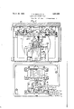
- Fig. 1 is a front View, partly sectioned, showing one form of relay embodying our invention.
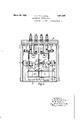
- 2 is a top view
- Fig. 3 an end view, of the relay shown in Fig. 1. Certain parts are broken away in all of the views for the purpose of more clearly illustrating the struc ture.
- the relay comprises the usual base plate D and top plate E spaced by side wall members, which plates support all of the operating parts of the device.
- This vane coacts with a motor device comprising two elements A and B, located on opposite sides of the vane and mounted on the base plate I).
- the motor element-A comprises a three-legged field member 23 provided with a winding 2 1 on the middle leg
- the motor element B comprises a U-sh'aped field member 25, provided with a winding 26.
- This motor device forms no "part of our present invention, and it is sufiicient to say that when the two windings 24 and 26 are supplied with alternating currents of one relative polarity, the vane V is ,turned in one direction, whereas, when these "windings are supplied with alternating currents of the opposite relative polarity, the vane is turned in the other direction.
- crank arm 8 Attached to the shaft S near one end of the shaft, is a crank arm 8, and attached to the shaft near its other end is a similar crank arm 8, which arms are disposed diametrically opposite to each other. Arm 8 is pro vided with a pin 9, which coacts with a slot 10 in an upwardly projecting link 11, and the upper end of this link is pivotally attached to a contact operating member 12.
- Member 12 is pivotally mounted at 13 in a Member 12 is biased by a counterweight li to swing in clockwise direction.
- the movement of the contact operating member 12 in response to the counterweight 14 is limited by a stop 15, and the member 12 is provided with a similar stop 15 for the same purpose.
- This mechanical brake comprises an arm 18, preferably of'fibre,” fixed to the V shaft S and projecting vertically down-v wardl'y-when the vane is in its middle position.
- the end of this arm coacts with an arm 19 'which is pivota-lly mounted'at 21 and is qwp'rovided withoa counterweight for normally biasing the arm 19 into the path of the arm 18.
- the movementof-the arm 19 in response to the bias of the counterweight 20 is limited by an adjusting screw. 22.
- arm 19 is preferably concaved, as shown in Fig.1.
- the parts of this braking device are so proportioned that when the vane V is re turningtowardfits middle position,,arm 18 will engage arm '19 when the vane is sub- -stantially away from the middle position, andthese parts will continue to engage 'until' the vane has swung substantially 30 beyond its middle position.
- the ⁇ rim tional engagement of the arms 18 and 19 will absorb theoiner'tiaimparted to the vane by the contactoperating'member 12 or 12 so that the vane will come to rest before it has movedSO" beyond its middlepesition, that is, before it has started to move the other contact operating member.
- the friction clutch for connecting the vane V with the shaft S is illustrated in Fig. 3,.
- A. relay comprising a pivotally mounted vane, electromagnetic means for moving said vane in opposite directions from a middle position, two contact arms each biased to a normal position, means for mov 'ing one arm or the other to a reverse position according as said vane moves in one direction or the other from such middle position, whereby when the vane is released by said electromagnetic means it is returned to the.
- a relay comprising a pivotally mounted vane, motor means'for moving said vane in opposite directions from a middle position, two contact operating members each biased to a normal position, means'for moving one member-or the other to a reverse positionaccording as said vane moves in one direction; or the other from such middle position, whereby when the vane hasreversed either member and is released it is movedtoward its middle position by the biasing force acting on such member, and a mechanical brake acting on said vane as it passes through the middle position to prevent the inertia imparted thereto by eitheroi said members from carrying the vanefarenough to reverse the other member.
- a relay comprising a pivotally mounted vane, motor'means for moving said vane in opposite directions from a middleposition, two contact operating members each biased to a normal position, means for moving one member or the other to a reverse position according as said vane moves in one direction 7 or the other from such ,middle position, whereby when the vane has reversed either member and is releasedit is moved toward its middle position by the biasing force acting on such member, a braking arm movingwith said vane, and a braking segment coacting frictionally with said armas the vane passes through the middle position to prevent the inertia impartedthereto by either of said' members from carrying the vane far enough I V to reverse the other member. 7 V r.
- a relay comprising a pivotally mounted vane, motor means for moving said vane in V opposite directions from a middle position, two contact operating members each biased to a normal position, means for movingone member or the other to a reverse position according as said vane moves in one direction *1 or the other from such middle position, whereby when the vanehas reversed eitherv mem her and is released it is moved toward its.
- a relay comprising a pivotally mounted vane, two contact operating members each biased to a normal position, means for moving one of said members or the other while said vane is moving between approximately 30 and 65 in one direction or the other from a middle position, and a mechanical brake acting on said vane during movement of the vane from a position approximately 30 on either side of such middle position to a position approximately 30 on the other side thereof.
- a relay comprising a pivotally mounted vane, two contact operating members each biased to a normal position, means for moving one of said members or the other while said vane is moving between approximately 30 and 65 in one direction or the other from a middle position, a braking arm moving with said vane, and a movable braking element having a concave surface biased toward the end of said arm and engaging the arm throughout movement of the vane from a position approximately 30 on either side of such middle position to a position approximately 30 on the other side thereof.
Landscapes
- Braking Arrangements (AREA)
Description
March 29, 1932. c R. BEALL ET AL 1,851,485
ALTERNATING CURRENT RELAY Filed Feb. 17, 1930 2 Sheets-Sheet l March 29, 1932.
C. R. BEALL ET AL ALTERNATING CURRENT RELAY iled Feb. 17, 1930 2 Sheets-Sheet 2 INVENTORS 1 C.R.BcaII, n R JLGUson,
Patented Mar. 29, 1932 UNITED STATES PATENT QFFECE CHARLES R. BEALL, OF EDGEWOOD BOROUGH, AND ROBERT M. GILSON, OF PITTSBURGH, PENNSYLVALTLQ, ASSIGNGES T THE UNION SWITCH & SIGNAL COMPANY OF SWISSVALE, PENNSYLVANIA, A. CORPORATION OF PENNSYLVANIA ALTERNATING CURRENT RELAY Application filed February 17, 1930. Serial No. 429,043.
Our invention relates to alternating current relays of the three-position vane type. One feature of our invention is the provision of a braking device acting on the vane of a relay of this character when the vane passes through its middle position.
We will describe one form of relay embodying our invention, and will then point out the novel features thereof in claims.
In the accompanying drawings, Fig. 1 is a front View, partly sectioned, showing one form of relay embodying our invention. 2is a top view, and Fig. 3 an end view, of the relay shown in Fig. 1. Certain parts are broken away in all of the views for the purpose of more clearly illustrating the struc ture.
Similar reference characters refer to similar parts in each of the views.
The relay comprises the usual base plate D and top plate E spaced by side wall members, which plates support all of the operating parts of the device.
Projecting upwardly from the base plate D are two standards 27 and 28 carrying trunnion screws 1 and 2, respectively, and a shaft S is mounted to rotate in these screws. A vane V of electro-conductive material is attached to the shaft S by means of a friction clutch C which is hereinafter described.
This vane coacts with a motor device comprising two elements A and B, located on opposite sides of the vane and mounted on the base plate I). The motor element-A comprises a three-legged field member 23 provided with a winding 2 1 on the middle leg, whereas, the motor element B comprises a U-sh'aped field member 25, provided with a winding 26. This motor device forms no "part of our present invention, and it is sufiicient to say that when the two windings 24 and 26 are supplied with alternating currents of one relative polarity, the vane V is ,turned in one direction, whereas, when these "windings are supplied with alternating currents of the opposite relative polarity, the vane is turned in the other direction.
Attached to the shaft S near one end of the shaft, is a crank arm 8, and attached to the shaft near its other end is a similar crank arm 8, which arms are disposed diametrically opposite to each other. Arm 8 is pro vided with a pin 9, which coacts with a slot 10 in an upwardly projecting link 11, and the upper end of this link is pivotally attached to a contact operating member 12.
The operation of the parts of the relay thus far deseribed,is as follows Normally the vane V occupies substantially the position in which it is shown in Fig. 1, wherein the pins 9 and 9 are both slightly above the mid points of the slots 10 and 10*. When the vane is turned in clockwise direction, as viewed in Fig. 1, pin 9 will move upwardly in the slot 10 until the vane has turned through an angle of substantially whereupon the pin will engage the upper end of the slot and will then swing the contact operating member 12 in clockwise direction until the back contact 16 has opened and the front contact 17 has closed. This will require a movement of the vane through substantially 65 from its middle position. During this entire operation pin 9' will move in the slot 10*, and so the operation will not be affected by the link 11 When the vane is turned in counter-clockwise direction, as viewed in Fig. 1, from its middle position, the operation will be the same as before, except that the contact member 12 will be operated and contact member 12 will remain at rest.
When the vane V has been turned to one extreme position to reverse one of the contact members 12 or 12*, and when the vane is then released by the motor device, the vane will be turned toward its mid- V dle position by the counterweight associated with the contact member which has been reversed. In the absence of means to prevent, the inertia which is thus imparted to the vane might be sufficient to cause-thevane to swing beyond its middle 1119 position far enough to'move the other contact operating member. To avoid this, we have provided a mechanical brake for retarding the motion of the vane as it passes through its middle position. This mechanical brake comprises an arm 18, preferably of'fibre," fixed to the V shaft S and projecting vertically down-v wardl'y-when the vane is in its middle position. The end of this arm coacts with an arm 19 'which is pivota-lly mounted'at 21 and is qwp'rovided withoa counterweight for normally biasing the arm 19 into the path of the arm 18. The movementof-the arm 19 in response to the bias of the counterweight 20 is limited by an adjusting screw. 22.
5 arm 19 is preferably concaved, as shown in Fig.1. The parts of this braking device are so proportioned that when the vane V is re turningtowardfits middle position,,arm 18 will engage arm '19 when the vane is sub- -stantially away from the middle position, andthese parts will continue to engage 'until' the vane has swung substantially 30 beyond its middle position. The {rim tional engagement of the arms 18 and 19 will absorb theoiner'tiaimparted to the vane by the contactoperating'member 12 or 12 so that the vane will come to rest before it has movedSO" beyond its middlepesition, that is, before it has started to move the other contact operating member. i
The friction clutch for connecting the vane V with the shaft S is illustrated in Fig. 3,.
and comprises two spaced collars 3 and 3 fixed to the shaft. A hub e is mounted to .rotate freely on the shaft between these collars, and this hub carries the vane V- Lo.-
cated between the hub 1 and the collar 3 is" a fibre washer 5, and located adjacent the other collar 3* isa metal washer 6. Interlposed between the washer 6 and the hub a r 'is a compression spring 7, so that this spring presses the washer 6 against the collar 3 and the washer 5 against the collar 3. The purpose of this clutch is to prevent rebound 55.0'f the'moving' parts when either front contact 17 or 17 becomes closed.
. Although we have herein shown and de scribed only oneforn of relay embodying our invention, it is understood that various q changes and modifications maybe made therein within the scope of, the appended The 1. A. relay comprising a pivotally mounted vane, electromagnetic means for moving said vane in opposite directions from a middle position, two contact arms each biased to a normal position, means for mov 'ing one arm or the other to a reverse position according as said vane moves in one direction or the other from such middle position, whereby when the vane is released by said electromagnetic means it is returned to the. middle position by the arm which had been reversed, and a mechanical brake acting on said vane when it passes throughsaid middle position to prevent the inertia imparted thereto by either of said arms from carrying the vane far enough to operate the other arm. 7 7 v 1 r "2. A relay comprising a pivotally mounted vane, motor means'for moving said vane in opposite directions from a middle position, two contact operating members each biased to a normal position, means'for moving one member-or the other to a reverse positionaccording as said vane moves in one direction; or the other from such middle position, whereby when the vane hasreversed either member and is released it is movedtoward its middle position by the biasing force acting on such member, and a mechanical brake acting on said vane as it passes through the middle position to prevent the inertia imparted thereto by eitheroi said members from carrying the vanefarenough to reverse the other member. s g r i V r 3. A relay comprising a pivotally mounted vane, motor'means for moving said vane in opposite directions from a middleposition, two contact operating members each biased to a normal position, means for moving one member or the other to a reverse position according as said vane moves in one direction 7 or the other from such ,middle position, whereby when the vane has reversed either member and is releasedit is moved toward its middle position by the biasing force acting on such member, a braking arm movingwith said vane, and a braking segment coacting frictionally with said armas the vane passes through the middle position to prevent the inertia impartedthereto by either of said' members from carrying the vane far enough I V to reverse the other member. 7 V r.
4. A relay comprising a pivotally mounted vane, motor means for moving said vane in V opposite directions from a middle position, two contact operating members each biased to a normal position, means for movingone member or the other to a reverse position according as said vane moves in one direction *1 or the other from such middle position, whereby when the vanehas reversed eitherv mem her and is released it is moved toward its.
''middle position by thebiasing force acting on such member, a braking arm moving with; saidvane, and a ,pivotally mounted braking,
element having a concave surface and biased to such position that when the vane passes through its middle position the end of said arm engages said surface with sufficient friction to prevent inertia imparted to the vane by either of said members from carrying the' vane far enough to reverse the other member.
5. A relay comprising a pivotally mounted vane, two contact operating members each biased to a normal position, means for moving one of said members or the other while said vane is moving between approximately 30 and 65 in one direction or the other from a middle position, and a mechanical brake acting on said vane during movement of the vane from a position approximately 30 on either side of such middle position to a position approximately 30 on the other side thereof.
6. A relay comprising a pivotally mounted vane, two contact operating members each biased to a normal position, means for moving one of said members or the other while said vane is moving between approximately 30 and 65 in one direction or the other from a middle position, a braking arm moving with said vane, and a movable braking element having a concave surface biased toward the end of said arm and engaging the arm throughout movement of the vane from a position approximately 30 on either side of such middle position to a position approximately 30 on the other side thereof.
In testimony whereof we aflix our signatures.
CHARLES R. BEALL. ROBERT M. GILSON.
Priority Applications (1)
| Application Number | Priority Date | Filing Date | Title |
|---|---|---|---|
| US429043A US1851485A (en) | 1930-02-17 | 1930-02-17 | Alternating current relay |
Applications Claiming Priority (1)
| Application Number | Priority Date | Filing Date | Title |
|---|---|---|---|
| US429043A US1851485A (en) | 1930-02-17 | 1930-02-17 | Alternating current relay |
Publications (1)
| Publication Number | Publication Date |
|---|---|
| US1851485A true US1851485A (en) | 1932-03-29 |
Family
ID=23701530
Family Applications (1)
| Application Number | Title | Priority Date | Filing Date |
|---|---|---|---|
| US429043A Expired - Lifetime US1851485A (en) | 1930-02-17 | 1930-02-17 | Alternating current relay |
Country Status (1)
| Country | Link |
|---|---|
| US (1) | US1851485A (en) |
-
1930
- 1930-02-17 US US429043A patent/US1851485A/en not_active Expired - Lifetime
Similar Documents
| Publication | Publication Date | Title |
|---|---|---|
| US3327811A (en) | Governor | |
| US2995043A (en) | Two position snap action operator | |
| US2460695A (en) | Sensitive switch actuator | |
| US1851485A (en) | Alternating current relay | |
| US1896850A (en) | Notching mechanism | |
| US2053961A (en) | Circuit breaker mechanism | |
| US1909138A (en) | Contactor | |
| US2081618A (en) | Switching mechanism | |
| US2586734A (en) | Electric centrifugal switch | |
| US2128205A (en) | Snubbing device for three-position relays | |
| US2420485A (en) | Electrical switch with kinetic energy dissipating means | |
| US2180677A (en) | Disk brake | |
| US1935303A (en) | Centrifugal switch | |
| US2318227A (en) | Circuit breaker | |
| US1695723A (en) | Time-element electroresponsive device | |
| US2360998A (en) | Circuit controller | |
| US1738406A (en) | Electric switch and operating means therefor | |
| US1557018A (en) | Short-circuiting device | |
| US1973324A (en) | Circuit maker and breaker | |
| US2233605A (en) | Circuit interrupter | |
| US1705692A (en) | Switch mechanism | |
| US2587557A (en) | Relay | |
| US1858242A (en) | Snap operating mechanism | |
| USRE15152E (en) | Switch mechanism | |
| US1493276A (en) | Delayed-action device |