US1851474A - Railway signaling track circuits - Google Patents
Railway signaling track circuits Download PDFInfo
- Publication number
- US1851474A US1851474A US536421A US53642131A US1851474A US 1851474 A US1851474 A US 1851474A US 536421 A US536421 A US 536421A US 53642131 A US53642131 A US 53642131A US 1851474 A US1851474 A US 1851474A
- Authority
- US
- United States
- Prior art keywords
- relay
- section
- track
- contact
- circuit
- Prior art date
- Legal status (The legal status is an assumption and is not a legal conclusion. Google has not performed a legal analysis and makes no representation as to the accuracy of the status listed.)
- Expired - Lifetime
Links
- 230000011664 signaling Effects 0.000 title description 2
- 150000001768 cations Chemical class 0.000 description 1
- 150000002500 ions Chemical class 0.000 description 1
- 230000003449 preventive effect Effects 0.000 description 1
Images
Classifications
-
- B—PERFORMING OPERATIONS; TRANSPORTING
- B61—RAILWAYS
- B61L—GUIDING RAILWAY TRAFFIC; ENSURING THE SAFETY OF RAILWAY TRAFFIC
- B61L1/00—Devices along the route controlled by interaction with the vehicle or train
- B61L1/18—Railway track circuits
- B61L1/181—Details
- B61L1/185—Use of direct current
Definitions
- My invention relates to railway signaling track circuits, vision of means operating when a short vehicle passes from one track section to an- 5 other, to insure that the track relay forthe forward section will release before the track relay for the rear section closes.
- the reference characters 1 and l designate the rails of a railway track, which rails are divided by insulated joints 7 to form two sections X and Y.
- Each section is provided with a trackbattery 2 connected across the rails of the section, and also with a track relay designated by the reference character T with an exponent corresponding to the section.
- Each section is also provided with a repeater relay P, and 1 a normally deenergized stick relay S.
- Track relay T is connected acrossfthe railsof its section through afront contact 5 of repeater relay P, and track relay T is connected across the front contact 5 of repeater relay P
- the circuit for track relay T ' is provided with a branch around contact 5 of relay P which branch includesa'back contact 3 of relay T and the circuit for relay T is provided with a second branch around contact 5 of relay P", which second branch includes a front contact 6 of relay S
- the circuit for track relay T is provided with two branches around contact 5 of relay P one of which branches includes back contact 3 of track relay T and the other of which branches includes front contact 6 of relay S includes front contact 4 of relay T the terminals of the source of current for this cirand has for an object the proright, relay S the rails of its sectionthrough Relay P is provided with a circuit whichis closed or open.
- Relay P is controlled in a' similar i manner by front contact 4g-of relay T
- Thestick relays S. are the usual directional sticlirelays of an "absolute permissive block ,signalingsystem, andinasmuchas the controlling circuits for theserelays form no part of the present invention, these circuits "are omitted from the drawing in order to simpli fy the disclosure.
- relay T willthen' be com on short circuit, so that this relay pleted through baclr contact 3 of relay T7,
- track relay T may be connected directly across the, railsof secibn Y',. andltrackvrelay T may be connected Ia,crossth e; rails of section. X. through contact of relay T and contact 5 of, relay P inmliltiple.
- the apparatuswil'l then function in the same manner. as before, in that when V-a, vehicle passes from: section Y to section X, the circuit for relay T will be immediately opened if'relay T 'be'comes energized before relay T releases.
Landscapes
- Engineering & Computer Science (AREA)
- Automation & Control Theory (AREA)
- Mechanical Engineering (AREA)
- Train Traffic Observation, Control, And Security (AREA)
Description
Filed May 11, 1931 INVENTOR.
H- S 0 u m BY M ATTORNEY.
Patented Mar. 29, 1932 UNITE STAT AT F' HENRY s. YOUNG, or 'WILKINSBURG, PENNSYLVANIA, ssre'ivon are THE UNIoN swrrcrr & SIGNAL COMPANY, or swIssvALnj PENNSYLVANIA; A CORPORATION or PENNSYLVANIA 'RAILW'AY SIGN LING; 'rn'Acx cmourrs Application filed May 11, 1931. Serial 110,536,421.
My invention relates to railway signaling track circuits, vision of means operating when a short vehicle passes from one track section to an- 5 other, to insure that the track relay forthe forward section will release before the track relay for the rear section closes.
'I will describe one form of track circuit apparatus embodying my lnvention, and will then point out the novel features thereof in claims.
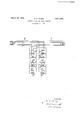
The accompanying drawing is a diagrammatic view showing one form of apparatus embodying my invention.
Referring to the drawing, the reference characters 1 and l designate the rails of a railway track, which rails are divided by insulated joints 7 to form two sections X and Y. Each section is provided with a trackbattery 2 connected across the rails of the section, and also with a track relay designated by the reference character T with an exponent corresponding to the section. Each section is also provided with a repeater relay P, and 1 a normally deenergized stick relay S.
Track relay T is connected acrossfthe railsof its section through afront contact 5 of repeater relay P, and track relay T is connected across the front contact 5 of repeater relay P The circuit for track relay T 'is provided with a branch around contact 5 of relay P which branch includesa'back contact 3 of relay T and the circuit for relay T is provided with a second branch around contact 5 of relay P", which second branch includes a front contact 6 of relay S Similarly, the circuit for track relay T is provided with two branches around contact 5 of relay P one of which branches includes back contact 3 of track relay T and the other of which branches includes front contact 6 of relay S includes front contact 4 of relay T the terminals of the source of current for this cirand has for an object the proright, relay S the rails of its sectionthrough Relay P is provided with a circuit whichis closed or open. Relay P is controlled in a' similar i manner by front contact 4g-of relay T Thestick relays S. are the usual directional sticlirelays of an "absolute permissive block ,signalingsystem, andinasmuchas the controlling circuits for theserelays form no part of the present invention, these circuits "are omitted from the drawing in order to simpli fy the disclosure.
when a tram moving toward the left passes I along the portion of track shown in the drawing,relay S will remain open, but relay S? will become energized when theflvehiclefen Similarly, when a'train moves'toward the Wlll remain open, but relay It issuflicient tosay that f "ters section X andfwill' remainenergized at least until the vehicle-leaves this. section.
S will become energized when the vehicle en ters section'Y least until the vehicle leaves this section.
Normally both track relays T and T and will remain energized at I are energized. When a train moving toward the left enters section Y, it will place r y T i will 0 "en, thereby closing its back contact 3. After a brief intervalof time following the release of relayT relay P 'willalso'open.
The circuit. for relay T willthen' be com on short circuit, so that this relay pleted through baclr contact 3 of relay T7,
but will be openec at'contacts 5' and6 ofre lays P and S respectively. When the 'for Ward wheels and axles of the vehicle enter.
section X, they will placeyrelay T pnshort circuit, therebydeenergizing therelay, but I a short interval of time'will elapse before the relay will release, because,, asis well un-j derstood,"when the coils of a' direct current relay circuit, I slow-releasingin character. It followsthat unless preventive means are provided, relay T inay remain are dee'nergized andplaced 011' short the relay automatically becomes 7 p closed until after the rear I wheels of the vehicle have left section Y and haveallowed relay Tito "close, Assuming nowthat relay Txremai'ns closed until the.
rear wheels leave section Y, the instant that relay T7 starts to closetitsback. contact 3 will p n,
and this will openfthe circuitfor relay T so release.
thatthe latter relay" will immediately It follows that there can be noin "stant of time duringwhich relays T and T are both closed while a vehicle is Idaimis;
i of section 'X, track relay T this will not interfere with r for section Y, Ibecause-"'contact Got 7 detailed explanaticn'f passing from section'Y into section X. The opening of relay T will cause relay S to close,'so that the circuit for relay T will then be closed at back contact 3. of relay T and from contact 6 of relay S J When the vehicle passes out will pick up, but the track circuit relay S' will still .beclosed. i Afterrel'ay 'P lpiek's up in response to the closing of relay T relay S will release and the apparatuswi-ll berestored to its normal condition. V i
, The operation of the apparatus during the assage of a vehicle from left to, rightwill e'understood from If traffic moves ill-only one "direction, the
apparatus can be considerabl Assuming, for example, that trafiie. moves only from right to left, track relay T may be connected directly across the, railsof secibn Y',. andltrackvrelay T may be connected Ia,crossth e; rails of section. X. through contact of relay T and contact 5 of, relay P inmliltiple. The apparatuswil'l then function in the same manner. as before, in that when V-a, vehicle passes from: section Y to section X, the circuit for relay T will be immediately opened if'relay T 'be'comes energized before relay T releases.
Although. Ii'have herein shown anddescribed only one formof'apparatus embodying myinvent-ion, it is understood that vari- V 'ous changes and modifi'cations may be made therteinwithin the scope? of the. appended contact of saidrepeater relay, and a shunt around said repeater relay front contact including a back contact of the track'relay for passing from the associated section into the other section to: momentarlly' disconnect the track relay for such other section. from at least one rail ofi-ts section.
In testimony whereof Iaflix my slgnature.
- HENRY S. YOUNG.
the foregoing without.
y simplified. x
claims without departing from the spirit and V e scope of'my invention. 7 v v Having thus describ'edm'y invention, what 1.. In combination, two adjoiningfsections of iiailway track, a source of track. circuit current foreach section,ifa track) relay for each section connected across'the rails ofits sect-ion through aback, contact-of. the other track relay, a slow-releasing repeater relay for each section controlledby afront contact of'the associatedtrack.relay, a normally open stick relay for; each, section arranged. to be- V come-closedlwhen avehiclepasses from the other" section; into thev associated section but notcwhen a vehicle moves'in the other direction, and a, branch. aroundeach ofsaid track relay back contacts including in multiple a front contact of' the associatedirepeater'remay, a e
lay'anda front contact offthe, associatedstiek T2; Incoinbination, a rear and. a forward a section; of railway-track, a track. circuit. in-
cludinga track. relay for the 'rear'sectioma slow-releasing, relay for the rearvr'sect'ion. con- 7 1 trolled,hy affrontcontact of said track re-= 1m; a; Jtracl'r relay for the forward section 65 icginnected' across the rails fthrou'gh a. front
Priority Applications (1)
| Application Number | Priority Date | Filing Date | Title |
|---|---|---|---|
| US536421A US1851474A (en) | 1931-05-11 | 1931-05-11 | Railway signaling track circuits |
Applications Claiming Priority (1)
| Application Number | Priority Date | Filing Date | Title |
|---|---|---|---|
| US536421A US1851474A (en) | 1931-05-11 | 1931-05-11 | Railway signaling track circuits |
Publications (1)
| Publication Number | Publication Date |
|---|---|
| US1851474A true US1851474A (en) | 1932-03-29 |
Family
ID=24138426
Family Applications (1)
| Application Number | Title | Priority Date | Filing Date |
|---|---|---|---|
| US536421A Expired - Lifetime US1851474A (en) | 1931-05-11 | 1931-05-11 | Railway signaling track circuits |
Country Status (1)
| Country | Link |
|---|---|
| US (1) | US1851474A (en) |
-
1931
- 1931-05-11 US US536421A patent/US1851474A/en not_active Expired - Lifetime
Similar Documents
| Publication | Publication Date | Title |
|---|---|---|
| US2391985A (en) | Railway signaling system | |
| US1851474A (en) | Railway signaling track circuits | |
| US1790524A (en) | Railway-signaling system | |
| US1877562A (en) | Signaling system for railroads | |
| US1786795A (en) | Railway-train-indicating apparatus | |
| US2017452A (en) | Railway signaling system | |
| US1916764A (en) | Railway signaling system | |
| US2174253A (en) | Apparatus for the control of highway crossing signals | |
| US3004150A (en) | Highway crossing protection systems | |
| US2021951A (en) | Railway signaling apparatus | |
| US2022074A (en) | Railway signaling apparatus | |
| US1823176A (en) | Railway track circuit apparatus | |
| US2133171A (en) | Controlling apparatus for highway crossing signals | |
| US2274289A (en) | Railway signaling apparatus | |
| US2354023A (en) | Traffic locking circuit | |
| US2280878A (en) | Railway track circuit apparatus | |
| US2042904A (en) | Railway traffic controlling apparatus | |
| US1925345A (en) | Railway switch controlling apparatus | |
| US1821602A (en) | Train indicating apparatus | |
| US2197425A (en) | Apparatus for the control of highway crossing signals | |
| US2159524A (en) | Railway signaling apparatus | |
| US1785725A (en) | Railway-traffic-controlling apparatus | |
| US1866144A (en) | Track circuit system | |
| US2045924A (en) | Continuous inductive train control system | |
| US1770822A (en) | Signaling apparatus |