US1851465A - Boiler - Google Patents
Boiler Download PDFInfo
- Publication number
- US1851465A US1851465A US276863A US27686328A US1851465A US 1851465 A US1851465 A US 1851465A US 276863 A US276863 A US 276863A US 27686328 A US27686328 A US 27686328A US 1851465 A US1851465 A US 1851465A
- Authority
- US
- United States
- Prior art keywords
- headers
- tubes
- drum
- disposed
- boiler
- Prior art date
- Legal status (The legal status is an assumption and is not a legal conclusion. Google has not performed a legal analysis and makes no representation as to the accuracy of the status listed.)
- Expired - Lifetime
Links
- XLYOFNOQVPJJNP-UHFFFAOYSA-N water Substances O XLYOFNOQVPJJNP-UHFFFAOYSA-N 0.000 description 31
- 239000007789 gas Substances 0.000 description 19
- 210000002445 nipple Anatomy 0.000 description 8
- 238000010438 heat treatment Methods 0.000 description 3
- RTZKZFJDLAIYFH-UHFFFAOYSA-N Diethyl ether Chemical compound CCOCC RTZKZFJDLAIYFH-UHFFFAOYSA-N 0.000 description 2
- 238000004140 cleaning Methods 0.000 description 2
- 238000010276 construction Methods 0.000 description 2
- 239000000463 material Substances 0.000 description 2
- 241001122767 Theaceae Species 0.000 description 1
- 239000000446 fuel Substances 0.000 description 1
- 230000002452 interceptive effect Effects 0.000 description 1
- 210000003041 ligament Anatomy 0.000 description 1
- 230000000284 resting effect Effects 0.000 description 1
- 238000011144 upstream manufacturing Methods 0.000 description 1
Images


Classifications
-
- F—MECHANICAL ENGINEERING; LIGHTING; HEATING; WEAPONS; BLASTING
- F22—STEAM GENERATION
- F22B—METHODS OF STEAM GENERATION; STEAM BOILERS
- F22B17/00—Water-tube boilers of horizontally-inclined type, i.e. the water-tube sets being inclined slightly with respect to the horizontal plane
- F22B17/10—Water-tube boilers of horizontally-inclined type, i.e. the water-tube sets being inclined slightly with respect to the horizontal plane built-up from water-tube sets in abutting connection with two sectional headers each for every set, i.e. with headers in a number of sections across the width or height of the boiler
Definitions
- This invention relates to a boiler, and more particularly one of the marine type, andresides in-the improvement of various features which will be best understood 'from the fo1-- lowing description.
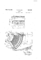
- Fig. 1 is a transverse sectional view through a' boiler setting showing one form which the invention may take, this view being taken ,on the li11e'11 of Fig. 3. f.
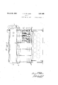
- Fig. 2 is a view takenon the line 2 2 of Fig. 1-
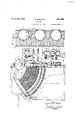
- Fig. 3 is a front elevation of the boiler shown in Fig. 1, taken on the line 33 of Fig. 1, parts being broken away.
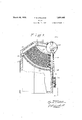
- Fig. 4 is a View similar to Fig. ing what I now consider the preferred form of my invention, this view being taken on the line 4-4. of Fig. 8. p I
- Fig. 5 is a fragmentary cross-section taken on the line 5-5. of Fig. 4..
- a Fig. 6 is a fragmentary view taken. on the line 6-6 of Fig. 4. i
- Fig. 7 is an enlarged detailed view showing the support for the lower superheater drum of Fig. 4.
- Fig. 8 is a View Fig. i and corresponding to Fig. 3.
- Fig. 9 is a view corresponding to Figs. 1 and 4,131.11] showing a still further form which my invention may take, this view being taken onthe line 99.of Fig. '10.
- Fig. 10 is a view taken on the line 10.-10 of Fig. 9, and corresponding to Figs. 3 and 8.
- a boilen setting having a front Wall 1 substantially vertical, and the rear wall 2 with its lower portion inclined inwardly and having disposedtherein a plurality of burners 3.
- burners may be of any suitable type, as for burning oil'or pulverized fuel.
- atrans- 1 Supported upon the front wall is atrans- 1, and. show taken from the right off verselyextending water ,4: whichis con n st by a plur ty e ti zbes 1. tea d u supported onthe rear wall 2.
- These tubes5 form a bank and are preferably curved on arcsof substantially. concentriccircles.
- each of the vertical headers 7 forms'part of one of a plurality of similar sections, the other parts of which. comprise aninclined header llconnected to the header .7 in the same section, by means ofa .nest 'of tubes 12 which are disposed substantially on arcs of concentric circles.
- the tubes 12 are so arranged'as to enter the l headers substantially normal to the fs'nrfaces thereof. .
- the axes of the two headers? and 11 ineach section are disposed substantially in acomrnon plane,a nd direct'ed substantially.
- the tubes 12 which'fall substantially in the same plane as the axes of the headers, may becurved,in only one plane,that is the plane including thesev axes or one" parallel 'thereto.
- the 5 tubes in each'section ' which are offset a sub- .stantial distance from the plane of thejaxes,
- each header 11 is connected to the drumi) by nipples 13 which are disposed on opposite sides .of the; axis of the header, as plainly shown in Fig. 2,and are disposed onechigher than the other, as shown inFig. 1, to furnish proper ligament strength in the drum and so as to provide a staggered arrangement of nipples across the pass through which the hot gases leave the boiler.
- each header 11 is connect-ed to the drum 6 by means of nipples 14.
- The' drum 9 is provided with the usual Fig. 5, inconnection with another form of I Outlet 21 9 is a pipe which conveys stearn'to a transverse drum 16 forming part of a'superheater, the otherpartsof which comprise a drum 1'? and the tubes 18 which connect the drums 16 and 17 and form a bank of tubes disposed between the tubes 5 and 12.
- a suitable strap 19 is provided atieach end of the boiler to feed water inlet 20, and the. superheater is provided with the usual outlet 21.
- the upper drum 16 is ia'rranged in two sections separated.at22,a's shown in Fig. 3,
- theheaders 7 and'11 are spaced apart and the space between two. adjacent headers is sufiicie'ntly great tojpermit removal of a tubethere'from'. In other words, this space is greater than the outsideidiameter of'a'tube;
- Eachheader is also provided with theusual handholes and handholefittings designated at23, and the spaces between thehe'aders maybe sealed by anysuitable means such asthat indicated 1n boiler, and" which will be 'in'ore fully describedflaterf A.
- casing 24 is disposed adja cent each set of headers, and each end of, the boiler is closed by a casing 25;
- This casing 25 is preferab'lymade in sections, the clivid i'ng lines between the sections being indicated at 26' inFi'g' l.
- the structurefso'far described provides a single pass boiler through whichthe hot gases 'fromthe burners3 maypass upwardly. over the tubes 12 and-betweennipples 13 through the 'flue 27. 'The pass tapers-sub- '50 stantially uniformly throughout its length, andthearrangement of tubes is' such as to provide for the maximum heating surface.
- the tubes in adjoining sections overlap eachother, andpreferably I the spacing of tubes-in both directions is less I 'than'a tube-diameter.- This close spacing is feasible in this construction because it is possible to remove a tube by lengthwise movernent 'thereofon the arc of its circle or, if
- the sections of the casing% are preferably arranged substantial 13 as v shown, so that ready access may be obtained to any portion of the'boiler,
- FIGs. l to 8' inclusive in which I have shown what I now consider my preferred form, I mountthe lower transverse drum 'i'upon' the front wall 29 of th'e setting, in whichwall are disposed the burners 30.
- the drums 4,6 and 9 are arin the form first described.
- the tubes. 12 are similarly arranged substantially on arcs of concentric circles,and-eXtend between headers 7 and 11', as in the first'described form.
- the superheater drums are made shorterv than in the firstembodi- 'mentf thelower' drum 31 ⁇ resting upon one rangedsubstantially in the same position as 7 or more bearings 82 which in'this formare in the first described form.
- the .two headers 7 support theupper'drum 9 above the superheater, and thus the drums 4: and 9 and headers v 7, form a frame to support headers 7.
- the other drum 33 ofthe superheater may 'besupported in the mannershown in Fig. 6, having one or both ends provided with anose 34 received within a pocket 35 on the header 7 i the intermediate 11.
- headers 11 at the opposite ends of the drum 33 extend down substantially to the drum 6 to which they may be connectedflbynipples-sun rounded by supporting collars,'inthe same manner as the headers 7 are'connected to" the drum 4, and the headers 11 are connected by nipples 36 to the drum 6.
- the two drums 31 and 33 are connected by the bank of tubes 18, and thus it will be seen that a construction is provided wherein one drum is fiXed'a-ndthe other drum may-beinoved lengthwise of the I tubes. I v r 1
- the various sections are spaced apart such a distance that the clearance between" a djacent headers is greater than a tube diameter-,5
- the sp'aces between the headers, boththe downtake and uptake, are filled with a suitable filling material 37 secured in place .amountfoi" heating" surface is "greatly increased; This increased heating surface is the iesult'partly otthe' closespacing of. the tubes, and this spacing s provided together with comparatively easy access to each tube;
- All of the tubes may be cleaned bya suitabletool inser'ted through the'handliolesfi'23,and) the; tubes may be removed either through the haudholes, or through the spaceslbetweenthe headers.
- the tubes areez'rpalndedintothe headers as nearly norinal as can be, and at the same tini'eperinit insertiqnsf a cleanin tool. It will be noted that substantially every tube' has its end directec. towarda handhole', so that the cleaning tool may be readily inserted into any tube. a tube entered a 1 header rsulially, or normal to the surface.
- the superheater need not be used at all times. "For example, if the boiler is used in a vessel and the vessel is in port where no steam is required, the burners which are locatedbeneath ,the superheater may be shut off, and
- the burners 42 are mounted the front wanes; this; wall supporting a transversely exteiiding' drum 44' which is con- 'form shown in n igs. 1 and 4.
- upstream downtaheheaclers .48 and 49' reg spectively are connected tothe' drums 46 and-4,byshort nipples shown.
- the upper ends ofthe headers i9 areconnected by short nipples directly to the steam and water drum 5O,'hilst the headers 48 are .conne'cted' by' "circulators- 51% to the steam drum.-
- the headers are connected bya bank of tubes 52 which are arranged in substantially thesame form'asf the tubes 12 previously described *Fed as in the water is V supplied at the inlet 20,
- I-CiaimzI- drum,fdowntake headers connected to said drum and spacedapart a distance greater than a tube diameter, a water drum disposed" 1.
- a water drum disposed
- a superheater comprising 'a bank'of ltubes 7 disposed between the'ltubes' of said; otherbeing spaced apart vertically.
- a 'paiiyof vertically extending headers have ingtheir lower, ends supported on saididrum and spaced apart, an-uppersteani and water drum. supported on the upper ends of said headers, a superheater header disposed above i said water drum; and between said headers, one or more "vertically extending V headers maladasupported bysaidsteam I and waterf'drum and having their lower ends disposed above the' superheater, means connecting the lower ends of said headers tosaid water drum, and meansrigidly securing s'aid headers to ether.
- a heat;transferdevice a pass or hot gases; a header disposedadjacentrone side of said pass, a drumdisposed substantially at) right angles to said header, anose formed on the; end vof said" druin on the outside thereof, and meansforming a pocket on the outsideof said header and'receiving said nose.
- a pass for hot" gases, uptake and downtake,headersdisposed onopposite sides of said. pass substantially parallelto the direction otfiow of gases therethrough, tubes extending across said pass and connecting said headers,'-drurnsdisposed substantially at right 'angles'. to said;
- drums being placed at opposite sides of the pass and connected by, tubes extending thereacross; meansslidablysupportingone of saidd'rum's' j to permit movement thereof, two-headers ad'- jacent the other drum; being extended aast' the ends thereof, projections on the en s of said drum,,and pockets iiiaid extended head- 7 I enjoyingo receivefsaidproj ect-ions. 1 f 9; Ina heattransfer device, a
- a row of downtake headers disposed beneath and Connected to said drum and extending downwardly therefrom, a row of uptake headersdisposed at an angle to the row of downtake headers and forming therewith a single gas pass narrowing in the direction of flow of said gases, the uptake headers each having one end thereof higher than'the other,
- a row' of downtake headers disposed beneath and connected to said drum and extending downwardly therefrom, a row of uptake headers disposed at an angle to the row of downtake headers and forming therewith a single gas pass narrowing in the direction of flow of said gases, the uptake headers each having one end thereof higher than the other, connections from said higher ends of the uptake headers to said drum, said headers being spaced apart in their rows, and a bank.
- tubes extendmg across said pass and connecting the uptake and downtake headers and substantially uniformly spaced apart a distance less than a tube diameter transversely of the lengths of the headers, said tubes for substantially their entire lengths being disposed in planes substantially normal to said rows and at. least some of said tubes bei 'ing bent adjacent their ends inadirection transverse to said planes to enter holes in said headers.
- a row of downtake headers disposed beneath and connected to said drum and extending downwardly therefrom, a row of uptake headers disposed at an angle to the row of downtake headers and forming therewith a single gas pass narrowing in the direction of fio-w of said gases, the uptake headers each having one end thereof higher than the other, connections from said higher ends of theuptake headers to said drunnsaid headers being spaced apart in their rows, and a bank of tubes extending across said pass and con necting the uptake and downtakeheaders and substantially uniformly spaced apart transversely of thelengths of the headers,
- said -tubes for 'risubstantiially their' entire len-gths being disposed-fin 5 planes 's'ubstan I connections from said higher ends of the uptake headers to saiddrum, said headersbe ing spaced apart in their; rows, and a bank of tubes extending across said pass and connesting the uptake anddowntake headers and substantially uniformly spaced aparta 1 distance less than a tube diameter transverse- 1y of thelengths of the, headers, said tubes v for substantially their entire lengths beingv disposed in planessubstantiallynormal to said rows and being, bent in said planes and at least some of sa1d tubes being bent ad-f jacent their ends in a direction transverse to said planest'oienter' holes in said headers; v
- a steam and water drum In a boller, a steam and water drum, a Y row of downtake headers and a row of up 7 take headers connected to said drum,-said headers being spaced apart in their rows, a
Landscapes
- Engineering & Computer Science (AREA)
- Physics & Mathematics (AREA)
- Thermal Sciences (AREA)
- Mechanical Engineering (AREA)
- General Engineering & Computer Science (AREA)
- Control Of Steam Boilers And Waste-Gas Boilers (AREA)
Description
March 29, 1932. B ST|LLMAN 1,851,465
BOILER I Filed May 11. 1928 6 Sheets-Sheet l N 1 INVENTO March 29,1932. T. B. STILLMAN BOILER Filed May 11, 1928 6 Sheets-Sheei 2 INVEN OR y- ATTORNEYS.
March 29, 1932. B, sTlLLMAN 1 ,851,465
BBBB ER March 29, 1932. T. B. STILLMAN 1,851,465
BOILER I Filed May 11, 1928 6 Sheets-Sheet 4 BZY; II %IANTOEE E: D
AFTOR N 5Y5,
March 29, 1932. T B 1,851,465
BOILER Filed May 11, 1928 6 Sheets-Sheet 5 I J M /o? BY MM ATTORNEYS.
Ma rch 29, 1932. T. B. STILLMAN BOILER Filed May 11. 1928 6 Sheets-Sheet 6 Patented Mar- 29, I932 UNETED STATES PATENT meag THOMAS B. STILLMAN, or SOUTH ORANGE, New annsnY, ASSIGNOB TO THE BAB7 oocK & IWILCOX coMrnnY, JERSEY Application filed. May 11.1328.v serial No. 276,863. r
This invention relates to a boiler, and more particularly one of the marine type, andresides in-the improvement of various features which will be best understood 'from the fo1-- lowing description. 1
In the accompanying drawings, 1 have shown selected embodiments of my invention, and referring thereto, i
Fig. 1 is a transverse sectional view through a' boiler setting showing one form which the invention may take, this view being taken ,on the li11e'11 of Fig. 3. f.
Fig. 2 is a view takenon the line 2 2 of Fig. 1- i Fig. 3 is a front elevation of the boiler shown in Fig. 1, taken on the line 33 of Fig. 1, parts being broken away.
Fig. 4 is a View similar to Fig. ing what I now consider the preferred form of my invention, this view being taken on the line 4-4. of Fig. 8. p I
Fig. 5 is a fragmentary cross-section taken on the line 5-5. of Fig. 4..
a Fig. 6 is a fragmentary view taken. on the line 6-6 of Fig. 4. i
Fig. 7 is an enlarged detailed view showing the support for the lower superheater drum of Fig. 4.
Fig. 8 is a View Fig. i and corresponding to Fig. 3.
Fig. 9is a view corresponding to Figs. 1 and 4,131.11] showing a still further form which my invention may take, this view being taken onthe line 99.of Fig. '10.
Fig. 10 is a view taken on the line 10.-10 of Fig. 9, and corresponding to Figs. 3 and 8. Referring first to Figs. 1, 2 and 3, I have shown therein a boilen setting having a front Wall 1 substantially vertical, and the rear wall 2 with its lower portion inclined inwardly and having disposedtherein a plurality of burners 3. These burners may be of any suitable type, as for burning oil'or pulverized fuel. p
. Supported upon the front wall is atrans- 1, and. show taken from the right off verselyextending water ,4: whichis con n st by a plur ty e ti zbes 1. tea d u supported onthe rear wall 2. These tubes5 form a bank and are preferably curved on arcsof substantially. concentriccircles.
Disposed above the drum l'is a plur.alityv or alumnus, new JERSEY,A conronemron'on new of vertically extending headers 7 connected to the drum 4 by nipples 8 and to a trans- Verse steam and water drum 9 by means of nippleslQ. Each of the vertical headers 7 forms'part of one of a plurality of similar sections, the other parts of which. comprise aninclined header llconnected to the header .7 in the same section, by means ofa .nest 'of tubes 12 which are disposed substantially on arcs of concentric circles.
.Preferablyfeach of the headersi and- :11
in each section is .cylindrical inform, and
the tubes 12 are so arranged'as to enter the l headers substantially normal to the fs'nrfaces thereof. .The axes of the two headers? and 11 ineach section are disposed substantially in acomrnon plane,a nd direct'ed substantially.
toward the center of the concentricicircles on which are disposed the tubes 12 The tubes 12 which'fall substantially in the same plane as the axes of the headers, may becurved,in only one plane,that is the plane including thesev axes or one" parallel 'thereto. The 5 tubes in each'section 'which are offset a sub- .stantial distance from the plane of thejaxes,
will be curved or bent at their ends at an 1 angle to thatplane, so as toybring their. endsv 'more nearly IlOIllfltllptO lthe surfacejof "the headers which they enter. It. is notessent-ial that these ends be disposed perfectly normal to the surface of the header which they enter, but it is desirable that they approach that relation to the headers as nearly'aspossible without interfering, with lea ing operations, as will be discussed later. 1 The upper end of each header 11 is connected to the drumi) by nipples 13 which are disposed on opposite sides .of the; axis of the header, as plainly shown in Fig. 2,and are disposed onechigher than the other, as shown inFig. 1, to furnish proper ligament strength in the drum and so as to provide a staggered arrangement of nipples across the pass through which the hot gases leave the boiler.
' The lower endof each header 11 is connect-ed to the drum 6 by means of nipples 14.
Leading from the steam spaceof the drum hold-the lower drum 17 of in position. n W The' drum 9 is provided with the usual Fig. 5, inconnection with another form of I Outlet 21 9 is a pipe which conveys stearn'to a transverse drum 16 forming part of a'superheater, the otherpartsof which comprise a drum 1'? and the tubes 18 which connect the drums 16 and 17 and form a bank of tubes disposed between the tubes 5 and 12. A suitable strap 19 is provided atieach end of the boiler to feed water inlet 20, and the. superheater is provided with the usual outlet 21. In this form, the upper drum 16 is ia'rranged in two sections separated.at22,a's shown in Fig. 3,
whereby the steam willenter' one section and pass'th'rough tubes 18 into the drum 17, back into the other section,'and thence into the As best shown in Figs. 2 and3, theheaders 7 and'11 are spaced apart and the space between two. adjacent headers is sufiicie'ntly great tojpermit removal of a tubethere'from'. In other words, this space is greater than the outsideidiameter of'a'tube; Eachheader is also provided with theusual handholes and handholefittings designated at23, and the spaces between thehe'aders maybe sealed by anysuitable means such asthat indicated 1n boiler, and" which will be 'in'ore fully describedflaterf A. casing 24 is disposed adja cent each set of headers, and each end of, the boiler is closed by a casing 25; This casing 25 is preferab'lymade in sections, the clivid i'ng lines between the sections being indicated at 26' inFi'g' l.
The structurefso'far described, provides a single pass boiler through whichthe hot gases 'fromthe burners3 maypass upwardly. over the tubes 12 and-betweennipples 13 through the 'flue 27. 'The pass tapers-sub- '50 stantially uniformly throughout its length, andthearrangement of tubes is' such as to provide for the maximum heating surface.
-By spacing the headers as shown,'and by arranging the handholes in the nianner'indi-' cateol, together withfthe-tubes disposed on arcs of concentric circles, it is possible to remove any tube inany section with a minimum amount of labor. a
' As shown inFig. 3, the tubes in adjoining sections overlap eachother, andpreferably I the spacing of tubes-in both directions is less I 'than'a tube-diameter.- This close spacing is feasible in this construction because it is possible to remove a tube by lengthwise movernent 'thereofon the arc of its circle or, if
' the superheater found desirable, it is posible to cut the nipples connecting'the headers to the various drums and, bodily rotate an entire section to remove it,-without disturbing the adjacent sections. This operation is made possible by the fact that, while the nest of tubes in each section may be widertha'n the Width. of the V headers of that section,-nevertheless the clear distance between alternate headers is at least as great as theoverall width of the nest of tubes in a section. At the same time, any
tube in a section maybe reached "for clean- 7 ing, by means of the handhol'es 23." The sections of the casing% are preferably arranged substantial 13 as v shown, so that ready access may be obtained to any portion of the'boiler,
.--without removing the entirecasing.
Referring now to'Figs. l to 8' inclusive, in which I have shown what I now consider my preferred form, I mountthe lower transverse drum 'i'upon' the front wall 29 of th'e setting, in whichwall are disposed the burners 30. In this form, the drums 4,6 and 9 are arin the form first described. The tubes. 12 are similarly arranged substantially on arcs of concentric circles,and-eXtend between headers 7 and 11', as in the first'described form. In thisform', however, the superheater drums are made shorterv than in the firstembodi- 'mentf thelower' drum 31 {resting upon one rangedsubstantially in the same position as 7 or more bearings 82 which in'this formare in the first described form. The .two headers 7 support theupper'drum 9 above the superheater, and thus the drums 4: and 9 and headers v 7, form a frame to support headers 7. I a .The other drum 33 ofthe superheater, may 'besupported in the mannershown in Fig. 6, having one or both ends provided with anose 34 received within a pocket 35 on the header 7 i the intermediate 11. Itwill be understood'that the headers 11 at the opposite ends of the drum 33 extend down substantially to the drum 6 to which they may be connectedflbynipples-sun rounded by supporting collars,'inthe same manner as the headers 7 are'connected to" the drum 4, and the headers 11 are connected by nipples 36 to the drum 6. The two drums 31 and 33 are connected by the bank of tubes 18, and thus it will be seen that a construction is provided wherein one drum is fiXed'a-ndthe other drum may-beinoved lengthwise of the I tubes. I v r 1 The various sections are spaced apart such a distance that the clearance between" a djacent headers is greater than a tube diameter-,5
' by plates 38 whichmay ers as shown in Fig. 5. Preferab-ly,-th h adand the tube's in each section are so arranged that the tubes iii-any row'will'be substantially unifoiu'nly" spaced across thebank oftu-bes" transversel-y to the length ofthe headers,-
best shown in Fig.5;- f The spacing of tubesis less; than; a tube diameter in both directions,transversely to they length of the headers;-
also parallel ther to. The sp'aces between the headers, boththe downtake and uptake, are filled with a suitable filling material 37 secured in place .amountfoi" heating" surface is "greatly increased; This increased heating surface is the iesult'partly otthe' closespacing of. the tubes, and this spacing s provided together with comparatively easy access to each tube;
both for renewal and cleaning. All of the tubes may be cleaned bya suitabletool inser'ted through the'handliolesfi'23,and) the; tubes may be removed either through the haudholes, or through the spaceslbetweenthe headers. The tubes areez'rpalndedintothe headers as nearly norinal as can be, and at the same tini'eperinit insertiqnsf a cleanin tool. It will be noted that substantially every tube' has its end directec. towarda handhole', so that the cleaning tool may be readily inserted into any tube. a tube entered a 1 header rsulially, or normal to the surface. of the header, hen itvvould be diflicult to insert a tool thereinto, and for that reason l prefer use thenonradial arrangement shown. This arrangement also makes possible, a closer spacingof tubes with a header'of giv n; diameter than is possible where the tubes enter the header radially thereto. spacing in turn makes-possiblefan increased efliciency of boiler fora given space.
Another feature of importance in connection with this embodiment, is thatthe superheater need not be used at all times. "For example, if the boiler is used in a vessel and the vessel is in port where no steam is required, the burners which are locatedbeneath ,the superheater may be shut off, and
only the burners at the other end of the boiler or those under theboiler tubes alone need be employed. i i
Referring now In this fornn'the burners 42 are mounted the front wanes; this; wall supporting a transversely exteiiding' drum 44' which is con- 'form shown in n igs. 1 and 4.
his closer I to Figs; 9 and I0. Ihave. shown therein amodilied form of boiler of ncted by a tank erases to upper drum 46 supported on the rear wall 47. The
upstream downtaheheaclers .48 and 49' reg spectively,"are connected tothe' drums 46 and-4,byshort nipples shown. The upper ends ofthe headers i9 areconnected by short nipples directly to the steam and water drum 5O,'While the headers 48 are .conne'cted' by' "circulators- 51% to the steam drum.- The headers are connected bya bank of tubes 52 which are arranged in substantially thesame form'asf the tubes 12 previously described *Fed as in the water is V supplied at the inlet 20,
In this form, I have, shownthe upper ends the" tubes 52 as being straight for a short distance as viewed in Fig. 9; The ends of'the curves on which the tubes are disposed, some approximately in the plane53 andathe'tubes are cont nued tangent -to th ose curves beyond this point as tarasban be Without'makingit impossible to remove a tube byvmovement on" Of course it is .underf stood that these portions of the, tubes which 7 appear straig'l'it in Fig. 9, are bent at an angle 9. r
the arc of its circle.
to theplane otgFiglS, tofenterthe headers 4:81"v
By the abovearrangen'ient 'oiitubes, a solnewhat greater i heated surface can be obtained,
without materially departingfrom thezad :vanta'ges obtained from the concentric arrangement of" tubes. In substantially all m other respects, this embodlment 18 similar to.
the one shown in FigsQE to 8 .inclusive,,ex-
cepft that it omits thesuperheater. I y, In; all forms shown, it will be seen'that there is provided'a heat transfer device havinga smgle'pass acrosswhichjthere is .ari ranged :a bank of tubes having closeuniformf spacing, the. spacing being' less than a tube diameterL 'This arrangement is Inadepos- .sibleby the curved tubes and bythe spaced headers. Thespaces between the headers.
and tubes adjacent their ends, is filled with the filling material 37, so'as topreventilaning or gases between theheaders. Similarly, laning. through the bank is prevented by the uniform spacing of tubes. Y V
I-CiaimzI- drum,fdowntake headers connected to said drum and spacedapart a distance greater than a tube diameter, a water drum disposed" 1. In aboiler,an andiwater beneath said headers and connected thereto,
a plurality of uptakeheaderseach ofwhich isconnected by a plurality of tubes to a downtake header, thetubes being disposed substantially on arcs of concentric circles and I the headers 'havingrhandholes providing access to'the tubes, connections betvveensaid uptake headers and said steam and water drum, a second water, drum disposed adja cent the lower ends of said uptake headers and generally parallel to said firstmamed water drum, connections between saidsecon'd water drum and saiduptake headers, and a:
' drum and spaced apart-,a distance greater *than a tube diameter,l a water drum disposed beneath said headers and connected-thereto,
bank of tubes connecting said water drums 2. Ina boiler, an upper steam and water drum, dwnta k e1 headers connected to said apluralityof uptake headers each of which is connected by a bank of tubes to a downtake header, theftubes I being disposed substantially on arcs of concentric circles and the headers having handholes providing ac uptake headers and said] steam and water cess to the 'tubes, connections between said drum, a second water drum" disposed. adja centthe lower ends of said uptake headers and generally parallel-to said first-named water drum, connections between said second 'water drum and said uptake headers, a bank of'tubes connectingsa-id water drums, and;
a superheater comprising 'a bank'of ltubes 7 disposed between the'ltubes' of said; otherbeing spaced apart vertically.
banks drums disposed beneath, said. headers; V v V v V i 3. In a boiler, a steam and water dru1n,'a
'V plurality of sections:comprising uptake; and downtakeheaders connected bytubes,1neans connecting said'downtake'headers to saidv drum, a plurality of circulators connecting theupper end of each uptake header to the drum, said cn'culators being disposed onopposite sides of the axis ofthe header and 4L In' a boiler, a horizontally extending water drum, means supporting saidgdrum,
a pairor" vertically extending'headers having their lower ends supported on said fdIUlTlw and spaced' apart, an upper steam and water,
- drum supported on the upper ends or" said headers, a sup-erlieatereheader disposed above saidfvzater drum and between 'saidheaders,
one. or morevertically extending "headers supported by 'said steam and: water drum and having their lowerends disposed above tubes disposed between said spaced'banks' and arallel to the tubestherein, and'means 6. In a boiler, a horizontally extending of concentric circles and so arranged that the, flow-of ase'sfis substantially toward thev center of said circles, a. bank of superheater connectingall of said tubes to the-circulating system of the'boilen;
Water druni, means supporting said drum,
- a 'paiiyof vertically extending headers have ingtheir lower, ends supported on saididrum and spaced apart, an-uppersteani and water drum. supported on the upper ends of said headers, a superheater header disposed above i said water drum; and between said headers, one or more "vertically extending V headers maladasupported bysaidsteam I and waterf'drum and having their lower ends disposed above the' superheater, means connecting the lower ends of said headers tosaid water drum, and meansrigidly securing s'aid headers to ether.
. 7. In a heat;transferdevice, a pass or hot gases; a header disposedadjacentrone side of said pass, a drumdisposed substantially at) right angles to said header, anose formed on the; end vof said" druin on the outside thereof, and meansforming a pocket on the outsideof said header and'receiving said nose. V
8, Ina'heattransfer device, a pass for hot" gases, uptake and downtake,headersdisposed onopposite sides of said. pass substantially parallelto the direction otfiow of gases therethrough, tubes extending across said pass and connecting said headers,'-drurnsdisposed substantially at right 'angles'. to said;
headers and at one end thereof, said drums being placed at opposite sides of the pass and connected by, tubes extending thereacross; meansslidablysupportingone of saidd'rum's' j to permit movement thereof, two-headers ad'- jacent the other drum; being extended aast' the ends thereof, projections on the en s of said drum,,and pockets iiiaid extended head- 7 I ersto receivefsaidproj ect-ions. 1 f 9; Ina heattransfer device, a
plane tubes extending inwardly from said headers across said pass and connected toother headers 011 theiopposite side ofthepass, a
drum" disposed with its axis substantially 'in pass forhot I gases, a plurality ofzheaders forming part of one side oflsaid pas's'with'the axes ofsaid "headers disposed substantiallyin the same the-same plane as the axes of saidgheaders but certain of said tubes,=with-the ends of said drrundisposed adjacent to certain ofs'aid headers, said last namedheaders extending across'jthe ends'of said drum andmeans on at right angles theretojand across the ends of I said last named headers forming supports forf V the ends of said drum.
.,10; Ina boiler, a steam and drum, a row of downtake headers disposedbene'ath, and connected to said,drum"andfextendingv downwardly therefro n, a-row of uptake headers disposed at an angle ;to,the row of I downtake headers and forming therewitlia; slngle gas pass narrowing in the direction of flowxof said gases, the uptakehead ers each having one end thereof higher than-the other, e connections from said higher ends of the uptakeheaders to said drum, saidh'eaders' being spaced apart in their rows,an"d a bank of tubes extending acrosssaid pass and connecting the uptake and downtake headers and substantially uniformly-spaced apart transversely' of the lengths of the 'headersfsaid tubes for substantially their entire lengths being disposed in planes substantially normal to' said rows and at least some of saidftubes be ing bent adjacenttheir endsin a direction transverse to said planes to enter holes in said headers.
11. In a boiler, a steam and water drum, a row of downtake headers disposed beneath and Connected to said drum and extending downwardly therefrom, a row of uptake headersdisposed at an angle to the row of downtake headers and forming therewith a single gas pass narrowing in the direction of flow of said gases, the uptake headers each having one end thereof higher than'the other,
- connections from saidhigher ends of the up take headers to said drum, said headers being spaced apart in their rows, and a bank of tubes extending across said pass and connecting the uptake and downtake headers and sub,- stantially uniformly spaced apart transverse ly of the lengths of the headers, said tubes for substantially their entire lengths being disposed in planes substantiallynormal to said rows and at least some of said tubes being bent adjacent their ends in a direction transverse to said planes to enter holes in said headers and said headers having circumfer- P entially curved surfaces to receive'said bent 7 ends.
12. In a boiler, a steam and water drum, a row' of downtake headers disposed beneath and connected to said drum and extending downwardly therefrom, a row of uptake headers disposed at an angle to the row of downtake headers and forming therewith a single gas pass narrowing in the direction of flow of said gases, the uptake headers each having one end thereof higher than the other, connections from said higher ends of the uptake headers to said drum, said headers being spaced apart in their rows, and a bank. of tubes extendmg across said pass and connecting the uptake and downtake headers and substantially uniformly spaced apart a distance less than a tube diameter transversely of the lengths of the headers, said tubes for substantially their entire lengths being disposed in planes substantially normal to said rows and at. least some of said tubes bei 'ing bent adjacent their ends inadirection transverse to said planes to enter holes in said headers. V
13. In a boiler, a steam and water drum, a row of downtake headers disposed beneath and connected to said drum and extending downwardly therefrom, a row of uptake headers disposed at an angle to the row of downtake headers and forming therewith a single gas pass narrowing in the direction of fio-w of said gases, the uptake headers each having one end thereof higher than the other, connections from said higher ends of theuptake headers to said drunnsaid headers being spaced apart in their rows, and a bank of tubes extending across said pass and con necting the uptake and downtakeheaders and substantially uniformly spaced apart transversely of thelengths of the headers,
tially norrnal to saidrows and being bent'in said planes and at least some'of, said tubes being bent adjacenttheir ends:in av direction transverse-to 1 planes to enter hele'si'n said headers. V
said -tubes for 'risubstantiially their' entire len-gths being disposed-fin 5 planes 's'ubstan I connections from said higher ends of the uptake headers to saiddrum, said headersbe ing spaced apart in their; rows, and a bank of tubes extending across said pass and connesting the uptake anddowntake headers and substantially uniformly spaced aparta 1 distance less than a tube diameter transverse- 1y of thelengths of the, headers, said tubes v for substantially their entire lengths beingv disposed in planessubstantiallynormal to said rows and being, bent in said planes and at least some of sa1d tubes being bent ad-f jacent their ends in a direction transverse to said planest'oienter' holes in said headers; v
15. In a boiler, a steam and water drum, a I
row of downtake headers disposed beneath and connected to said drumand extending downwardlytherefrom,arowof uptakehea-dj a ers disposed at an angle to the row of down take headers and forming therew th a single gas pass narrowing in the direction of flow-H f of said gases, said headers being cylindricalin cross sectionand spaced apart, in their rows a distance greater thana tube diameter, the uptake headers each. having oneend thereof higher than the other, connections from said higher ends of the uptake headers said drum and extending across the narrow end of said pass, and a bank of tubes extending across said pass and connecting the uptake and downtake headers and substantially. uni-f formly spaced apart a distance-less than a tube diameter transversely of the lengths of the headers,'sa'id tubes for substantially their en- I tire lengths beingdisposed in planes substan-.
tially normal to said rowsand being bent in I said planes and at least some of said tubes being bent adjacent their ends in adi'rection transverse to -said planes to enter-holes in-the.
cylindrical walls of said headers. l
16. In a boller, a steam and water drum, a Y row of downtake headers and a row of up 7 take headers connected to said drum,-said headers being spaced apart in their rows, a
bank of tubes extending between said rows 7 i and. connecting the uptake and downtake headers and substantially uniformly spaced apart transversely of the length of the headers, said, tubes for substantially their entiret-HI j lengthsjbeing disposed inlplanes substantialf 1y normal tov said rows and at least some; of said tubes being bent; adj acent, their. ends in a direction transversevte said-planes to enter hples in'said headers, means closing the spaces Y 1 between-said headers to prevent escape'of gases therebetween, and means extending inwardly between said headers and between said bent ends of said tubes tolprevent'laningpf H 71G gases in a direction parallel to .the lengths of I V the headers.
I I TH'QMAS 1B1 SZTILLMAN.
f p 20 t
Priority Applications (1)
| Application Number | Priority Date | Filing Date | Title |
|---|---|---|---|
| US276863A US1851465A (en) | 1928-05-11 | 1928-05-11 | Boiler |
Applications Claiming Priority (1)
| Application Number | Priority Date | Filing Date | Title |
|---|---|---|---|
| US276863A US1851465A (en) | 1928-05-11 | 1928-05-11 | Boiler |
Publications (1)
| Publication Number | Publication Date |
|---|---|
| US1851465A true US1851465A (en) | 1932-03-29 |
Family
ID=23058382
Family Applications (1)
| Application Number | Title | Priority Date | Filing Date |
|---|---|---|---|
| US276863A Expired - Lifetime US1851465A (en) | 1928-05-11 | 1928-05-11 | Boiler |
Country Status (1)
| Country | Link |
|---|---|
| US (1) | US1851465A (en) |
-
1928
- 1928-05-11 US US276863A patent/US1851465A/en not_active Expired - Lifetime
Similar Documents
| Publication | Publication Date | Title |
|---|---|---|
| US1851465A (en) | Boiler | |
| US1810178A (en) | Heat transfer device | |
| US1859857A (en) | Water tube boiler | |
| US1775079A (en) | Superheater boiler | |
| US1629005A (en) | Steam superheater for locomotives | |
| US1726234A (en) | Water-tube boiler | |
| US465164A (en) | Water-tube boiler | |
| US486731A (en) | Steam-boiler | |
| US1953588A (en) | Boiler construction | |
| US1764431A (en) | High-pressure locomotive | |
| US570229A (en) | steam generator | |
| US1704388A (en) | Steam boiler | |
| US487075A (en) | Steam-boiler | |
| US1906125A (en) | Boiler with interdeck superheater | |
| US558778A (en) | Steam-generator | |
| US2088940A (en) | Boiler | |
| US1851010A (en) | Steam boiler | |
| US1818390A (en) | Boiler | |
| US1360096A (en) | Superheater | |
| US658110A (en) | Steam-boiler. | |
| US620566A (en) | Steam-boiler and furnace | |
| US1807238A (en) | Boiler | |
| US1905465A (en) | A cobpobatiom | |
| US1558379A (en) | Water-tube boiler or the like | |
| US474887A (en) | Boiler |