US1851464A - Single pass marine boiler - Google Patents
Single pass marine boiler Download PDFInfo
- Publication number
- US1851464A US1851464A US199167A US19916727A US1851464A US 1851464 A US1851464 A US 1851464A US 199167 A US199167 A US 199167A US 19916727 A US19916727 A US 19916727A US 1851464 A US1851464 A US 1851464A
- Authority
- US
- United States
- Prior art keywords
- tubes
- headers
- boiler
- section
- water
- Prior art date
- Legal status (The legal status is an assumption and is not a legal conclusion. Google has not performed a legal analysis and makes no representation as to the accuracy of the status listed.)
- Expired - Lifetime
Links
- XLYOFNOQVPJJNP-UHFFFAOYSA-N water Substances O XLYOFNOQVPJJNP-UHFFFAOYSA-N 0.000 description 18
- 239000007789 gas Substances 0.000 description 13
- 210000002445 nipple Anatomy 0.000 description 11
- 238000002485 combustion reaction Methods 0.000 description 2
- 239000000446 fuel Substances 0.000 description 2
- 239000002912 waste gas Substances 0.000 description 2
- OWNRRUFOJXFKCU-UHFFFAOYSA-N Bromadiolone Chemical compound C=1C=C(C=2C=CC(Br)=CC=2)C=CC=1C(O)CC(C=1C(OC2=CC=CC=C2C=1O)=O)C1=CC=CC=C1 OWNRRUFOJXFKCU-UHFFFAOYSA-N 0.000 description 1
- 241000353097 Molva molva Species 0.000 description 1
- 238000010521 absorption reaction Methods 0.000 description 1
- 239000010425 asbestos Substances 0.000 description 1
- 238000010438 heat treatment Methods 0.000 description 1
- 239000000463 material Substances 0.000 description 1
- 238000000034 method Methods 0.000 description 1
- 239000000203 mixture Substances 0.000 description 1
- 238000012856 packing Methods 0.000 description 1
- 230000000717 retained effect Effects 0.000 description 1
- 229910052895 riebeckite Inorganic materials 0.000 description 1
- 238000000926 separation method Methods 0.000 description 1
Images

Classifications
-
- F—MECHANICAL ENGINEERING; LIGHTING; HEATING; WEAPONS; BLASTING
- F22—STEAM GENERATION
- F22B—METHODS OF STEAM GENERATION; STEAM BOILERS
- F22B17/00—Water-tube boilers of horizontally-inclined type, i.e. the water-tube sets being inclined slightly with respect to the horizontal plane
- F22B17/10—Water-tube boilers of horizontally-inclined type, i.e. the water-tube sets being inclined slightly with respect to the horizontal plane built-up from water-tube sets in abutting connection with two sectional headers each for every set, i.e. with headers in a number of sections across the width or height of the boiler
Definitions
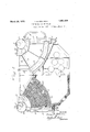
- Fig. 1 is a side view of the.
- Fig. 2 is a half section along the line 22 of Fig. 1;
- Fig. 3 is a section along the line 3-3 of Fig. 2;
- Fig. 4 is a section along transverse to the theline 4 l ofFig. 3, and
- Fig. 5 is a'section similar to Fig. 4 partly broken away and shown on an enlarged scale. Since the two units of the boiler are duplicates, it is thought sufiicient to describe only one of them.
- Outer and inner vertically disposed downtake headers 11 and a. 12 that are staggered withrespectto each other, as shown in Fig. 4, are connected to thewater spaceo'f the steamandwater drum- 1O bynipples Band 14, and mud drums 15 and 16 are connected by nipples to the, lower straps 15 to the girders or supports 16.
- the headers 11and 12 are connected by means of curved tubes 17 to the inner and outer inclined headers 18' and 19, respectively.
- These headers 18 and'l9 are also'staggere with respect to each other, and are connected by nipples 20 and 21 to thesteam space of the drum 10, and a baffle 22 is placed in the drum tofacilitate separation of steam and water.
- An outlet 23 leads from the steam space of the drum to the inlet 2% of asuperheater that is divided into two sections as for example by a diaphragm near its center.
- U-shaped superheater tubes 25 connect the inletheader 24s at one side of the boiler to a header-26 at the other side thereof, and from header26 similar U-shaped tubes 27 lead to the' outlet superheater header 28, disposed on the same 7 side of the boiler as the header 24, and from which a connection 29 leads to a steam main.
- U-tubes 25, and27 "extend through the; space between-rows of tubes 17 that isleft for thatpurpose, and the tubes 25 and 27 are are located along the front of the furnace located, may 7 g y is desirable, so that the hot products ofcomsuperheater tubes H tubes 17 Fuel burners -30,
- the headers for the tubes 17 arespaced of the neadersat each end ,of thetubes .v-hichrods are not quite. large enoughtof entirelyflclose the space between] the corners of theheaders.
- the headers are preferably jl made sinuous in shape, and the rods 35am 7 correspondingly shaped.
- the rods 35 serve asst-ops for packing material 36,] such as asbestos, that is placed in thespaeesbetween the headers to prevent lealragev of gas, 0123,11.
- This boiler is sultablef for operation at' V high steam pressure; the velocity of the J across the tubes" into a plurality of relatively narrow or thin layers or streams-and makes gases across the tubes is kept approximately constant bythe'contracting area of the gas ples to thesteamandwater drum and connected together by means of a plurality of nests of tubes.
- the headers are sinuous so that the nests are, staggere'd with relation to one another, and as plainly shown in Figs. 3 and 4,1,the clear space between any two tubes in a nest'is less than a tube diameter, and each tube is staggeredwith relation-to -th'e other tubes in the nest.
- an entire section may; beresingle section can be moved-substantially its" entire length, until the header at the other end of the section comes in contact-with the" headers onfeither side' of 'the section.
- this section including the I header 11 can be moved outwardly, so as to 7 .move the header 11 away from the headers 12, until the header at the other end of the tubes connected tothe headerll, comes in 1 contact with the headers 12'. Forsome purposes, this movement may be sufficient and if lt-is desired to remove an entire section, thls 'may be done by removing apair of adjacent sections. ;After one sectionhas been moved longitudinally with respect'to the otherin a pair, suflicient lateral movement of'thisadjacentsectionin the pair is possible to peri I mit the two to be removed together. There- ,fore,yif,one.section alone is to be removed,
- said tubes being arranged in :spaced: banks and the' -headers in each :sectionbeing dis-1' posed at an angle to each other and corresponding headers in adjacent sections being substantially parallel to each other, means forming closures between adjacent headers whereby the headers of the section form a tapered gas pass, means for burning fuel adjacent the wide end of said pass, a gas outlet two spaced banks, and a superheater having tubes extending into said pass between spaced staggered 6.
- a steam boiler'hand its setting a.
- a'plurality of water tubes connecting said headers and disposedsubstantially on arcs of concentric circles, said water tubes comprising two spaced banks, a superheater having headers extending lengthwise of and generally parallel to the space between said banks, and tubes connected to said headers and extending into said space transversely of the lengths of the water tubes.
Landscapes
- Engineering & Computer Science (AREA)
- Physics & Mathematics (AREA)
- Thermal Sciences (AREA)
- Mechanical Engineering (AREA)
- General Engineering & Computer Science (AREA)
- Heat-Exchange Devices With Radiators And Conduit Assemblies (AREA)
Description
March 29, 1932. T. B. STILLMAN SINGLE PASS MARINE BOILER Filed June 16, 1927 2 Sheets-Sheet l m INVENTOR ATTORNEYS;
March 29, 1932. T. B. STILLMAN SINGLE PASS MARINE BOILER Filed June 16, 1927 2 Sheets-Sheet 2 INVENTOR MW I BY A? I 17M.
AT ORNEYS I a (mine srA Patented Mar. 29, 1932 res Y'A E OF I THOMAS B. STILLMAN', OF SOUTH ORANGE; NEW JERSEY, ASSIGNOB r ant: 3A3 ooox & WILGOX COMPANY, or BAYONNE,,NEW JERSEY, A .oonro'R 'rroiror NEW JERSEY SINGLE PASS, MARINE BOILER Application filed June is, 1927. Serial lid-199,167.
This invention relates to a marine boiler having two unlts locatedv above a furnace with a steam and water drumfor-each unit, and will be understood from the description 1n connection with the accompanying drawings, in which Fig. 1 is a side view of the.
boiler; Fig. 2 is a half section along the line 22 of Fig. 1; Fig. 3 isa section along the line 3-3 of Fig. 2; Fig. 4 is a section along transverse to the theline 4 l ofFig. 3, and Fig. 5 is a'section similar to Fig. 4 partly broken away and shown on an enlarged scale. Since the two units of the boiler are duplicates, it is thought sufiicient to describe only one of them.
In the drawings, reference character 1-0 in-.
dic ates a steam and water drum on one side of and above the furnace. Outer and inner vertically disposed downtake headers 11 and a. 12 that are staggered withrespectto each other, as shown in Fig. 4, are connected to thewater spaceo'f the steamandwater drum- 1O bynipples Band 14, and mud drums 15 and 16 are connected by nipples to the, lower straps 15 to the girders or supports 16.
The headers 11and 12are connected by means of curved tubes 17 to the inner and outer inclined headers 18' and 19, respectively. These headers 18 and'l9 are also'staggere with respect to each other, and are connected by nipples 20 and 21 to thesteam space of the drum 10, and a baffle 22 is placed in the drum tofacilitate separation of steam and water. An outlet 23 leads from the steam space of the drum to the inlet 2% of asuperheater that is divided into two sections as for example by a diaphragm near its center. U-shaped superheater tubes 25 connect the inletheader 24s at one side of the boiler to a header-26 at the other side thereof, and from header26 similar U-shaped tubes 27 lead to the' outlet superheater header 28, disposed on the same 7 side of the boiler as the header 24, and from which a connection 29 leads to a steam main.
The. U-tubes 25, and27 "extend through the; space between-rows of tubes 17 that isleft for thatpurpose, and the tubes 25 and 27 are are located along the front of the furnace located, may 7 g y is desirable, so that the hot products ofcomsuperheater tubes H tubes 17 Fuel burners -30,
wall in sucha position that fueliisprojected into the furnace in a: dlrection transverseto thetubes 17,'and a waste gas outlet is located.
above'the nipples 20 and2l,asshown at 31. slightly apart with their edgesoverlapplng, I
a The headers for the tubes 17 arespaced of the neadersat each end ,of thetubes .v-hichrods are not quite. large enoughtof entirelyflclose the space between] the corners of theheaders. The headers are preferably jl made sinuous in shape, and the rods 35am 7 correspondingly shaped. The rods 35 serve asst-ops for packing material 36,] such as asbestos, that is placed in thespaeesbetween the headers to prevent lealragev of gas, 0123,11.
.The operation is as; follows 2 Fuelis intro-v duced into the furnace through theburners '30 in a somewhat horizontal direction and as it undergoes combustion, the hot prod;
nets of ,combustion rise on each side; and pass onceacross the tubes 17, andalso across the superheater tubes finally passing between the-nipples 2O and21, andlthrou'gh the outlet,
31 to the stack. lVater circulates downward d ly through 'the.nipples"13 and into the downtake headers 11 and12, and passes through the tubes 17. where. steam is 'gener; ated, and he mixture of steam and water passes into the headers 18 and- 19, thence throughthe nipples 20 and 21into the steam and water drums. The'waste gases passonly' once across the tubes 17, where steam is gen erated, thence across the nipples 20 J and 21; that are heated bysome of the heat rernain ing-in the hot gases,thusfacilitating the. circulation through the system;
The. space between therows of tubes 17. in which the superheater tubes 25 and 2.? are; be made asnearthe furnace-as bustion will pass across the after they have first passed across the de,
sirable number of water tubes.
This boiler is sultablef for operation at' V high steam pressure; the velocity of the J across the tubes" into a plurality of relatively narrow or thin layers or streams-and makes gases across the tubes is kept approximately constant bythe'contracting area of the gas ples to thesteamandwater drum and connected together by means of a plurality of nests of tubes. Inthe form-shown, the headers are sinuous so that the nests are, staggere'd with relation to one another, and as plainly shown in Figs. 3 and 4,1,the clear space between any two tubes in a nest'is less than a tube diameter, and each tube is staggeredwith relation-to -th'e other tubes in the nest. This arrangement, promotes heat absorption byi sub-dividing the gas stream possible'an increase in the heating surface per cubic foot of space occupied by the tubes, thereby maki'n'ga high capacityboiler of relatively light weight and giving; it. high efliciency. TAt the same time, the arranger ment renders it diflicultto remove tubes in a" nest by 'movement transversely of their lengths However, such removal and {replacement of tubes is made possible in this constructiomf by, arranging them substan tially on arcs of concentric circles and by providing handholes inthe headers of sufli-' cientsize topermit removal of tubes therethrough. Eachtube'may" be then removed and replaced by movement along the. arc of thecircletowhichitcorresponds; f
It will also'be noted that the nestsof tubes that would, b'e'ditficult if not impossible, to
remove-and replace an entire section by x movement of thesection transverselyof the length of the tubes. According tomyinvention, however, an entire section" may; beresingle section can be moved-substantially its" entire length, until the header at the other end of the section comes in contact-with the" headers onfeither side' of 'the section. For
moved and replaced by movement aboutthe common center of'the circl-eson which the tubes are, disposed. In the form shown,- a single section could notbe entirely removed bythis method, Without severing the tubes connected to one of theheaders, becauseof the overlapping relation of thehead'ers in adjacent-sections. Obviously, however, if the 'header's were-placed'on a linewith each 7 otherasis'common practice, then the entire;
7 section could be removed without cutting-the tubes. 1 Obviously, the connecting nipples at the ends of the headers must becut, before such removal can be had. V, c t 7 WJth the arrangement shown, however, a
are staggered with respectto each-other and that'the headers are preferably sinuous so example, in Fig." 4, this section including the I header 11, can be moved outwardly, so as to 7 .move the header 11 away from the headers 12, until the header at the other end of the tubes connected tothe headerll, comes in 1 contact with the headers 12'. Forsome purposes, this movement may be sufficient and if lt-is desired to remove an entire section, thls 'may be done by removing apair of adjacent sections. ;After one sectionhas been moved longitudinally with respect'to the otherin a pair, suflicient lateral movement of'thisadjacentsectionin the pair is possible to peri I mit the two to be removed together. There- ,fore,yif,one.section alone is to be removed,
it may be donewith a minimum amount-of labor, by "merely removing it" together with. one of the sections adjacent thereto.
By my invention, I achieve all the advantages which are inherent in a singletapering gaspass, which passis formed bythe inclined headers and, at the same t1me', I make it possible to remove'and replace individual tubes,
or indeed sections of tubes without difficulty andw thout sacr ficing close spacing, in orderto obtain easy removability. 'Theta-perlin-g gas pass results in uniform gasj flow resist ance from the fireside of the tubes to the fluegside thereof, thus increasing mass flow of the gases as they'cool, without draft-loss caused by the use of battles.
By my invention, l have retained the ad vantages -ofthe tapering gas pass and}; at
the-same time, have:madefit' possible to employ relatively small tubesclosely. spaced, 'thereby,obtaining increased'efiiciency; It will also be noted that the longestjtubes'" are disposed on their convex side to' the heat of the-"fire, for substantially-their entire leng'gth,
ficiencyfof the entire structu-re. e
which is another advantage adding to'the' ef- Another feature whichaddsto the efficiency of this boiler, is-the arrangement: of the in tended: superheater with the headers-preferably curved concentrically with the water tubes between which the'superheater tubes are disposed. This constructiongives a high,-
superheat and uniformsteam temperature in a superheater and, at the same time, conserves space, thereby making possiblethe:use of the maximum number of tubes and, at the: same time, permitting easyremova-l and replace= men't of'the s'uperheater tubes and sections' as I wellas the waterltubes. .7 I "Changes; may be made in details withoutdeparting from the spirit or scopeof the in-l vention. c. I claim: 7 i 1. In a boiler, a plurality-of section's, eachcomprising a pair of headers'connectediby' aplurality of-water tubes spaced apart a"dis tance less than a'tube diameter anddisposed.
substantially on arcs'of concentric. circles,
' said tubes being arranged in :spaced: banks and the' -headers in each :sectionbeing dis-1' posed at an angle to each other and corresponding headers in adjacent sections being substantially parallel to each other, means forming closures between adjacent headers whereby the headers of the section form a tapered gas pass, means for burning fuel adjacent the wide end of said pass, a gas outlet two spaced banks, and a superheater having tubes extending into said pass between spaced staggered 6. In a steam boiler'hand its setting, a.
steam and water drum, vertically'disposed front headers and inclined rear headers arg ranged in staggered relation and connected to said drum by staggered nipples, said front headers being located beneath said drum and connected thereto by short nipples, tubes connecting said frontand rear headers and curved on the. arc of a circle and concentrically'located for substantially their entire lengths,'and an outlet flue above said stag gered nipples, the gases flowing over the tubes in a slngle pass from the-longftubes to I the short ones and'passing between said nipples to said outlet flue. THOMAS B. STILLMAN.
banks of said water tubes, and having headers curved concentrically with said water tubes for the purposes set forth. i
3. In a boiler, a plurality of sections, each comprising a pair ofheaders connected by nests of tubes staggered with relation to;
nests of tubes in adjacent sections and with the clear space between tubes less than a tube diameter, whereby removal of a section or a tube therein transversely of the length of the tubes is rendered diflicult, the headers defining-a single pass across the tubes and the headers of a pair of adjacent sections voverlapping each other, whereby complete removal of a single section is rendered difficult, thetubes being arranged substantially on arcs of concentric circles, whereby an individual tube may be removed byrotating it about the common center of said circles, and whereby an entire section in said pair may be moved in the same manner as a single tube and thereby permit removal of said pair of sections. v
4:. In a boiler, headers inclined to each other and forming a single tapered gas pass,
a plurality of water tubes connecting sa1d' headers and disposed substantially on arcs of concentric circles, said water tubes comprising two spaced banks, and a superheater having tubes extendin into said pass between said spaced banks, ancfhaving headers curved concentrically with said water tubes, [the tubes of said superheater extending transversely of the water tubes.
'5. In a boiler, headers, lnclined to each other and forming a single tapered gas pass,
a'plurality of water tubes connecting said headers and disposedsubstantially on arcs of concentric circles, said water tubes comprising two spaced banks, a superheater having headers extending lengthwise of and generally parallel to the space between said banks, and tubes connected to said headers and extending into said space transversely of the lengths of the water tubes. 3
Priority Applications (1)
| Application Number | Priority Date | Filing Date | Title |
|---|---|---|---|
| US199167A US1851464A (en) | 1927-06-16 | 1927-06-16 | Single pass marine boiler |
Applications Claiming Priority (1)
| Application Number | Priority Date | Filing Date | Title |
|---|---|---|---|
| US199167A US1851464A (en) | 1927-06-16 | 1927-06-16 | Single pass marine boiler |
Publications (1)
| Publication Number | Publication Date |
|---|---|
| US1851464A true US1851464A (en) | 1932-03-29 |
Family
ID=22736498
Family Applications (1)
| Application Number | Title | Priority Date | Filing Date |
|---|---|---|---|
| US199167A Expired - Lifetime US1851464A (en) | 1927-06-16 | 1927-06-16 | Single pass marine boiler |
Country Status (1)
| Country | Link |
|---|---|
| US (1) | US1851464A (en) |
-
1927
- 1927-06-16 US US199167A patent/US1851464A/en not_active Expired - Lifetime
Similar Documents
| Publication | Publication Date | Title |
|---|---|---|
| US2232935A (en) | Fluid heater | |
| US1851464A (en) | Single pass marine boiler | |
| US1839125A (en) | Steam boiler | |
| US1911501A (en) | Steam generating apparatus and method | |
| US2342148A (en) | Vapor generator | |
| US1950454A (en) | Boiler furnace | |
| US1975789A (en) | Boiler | |
| US1027815A (en) | Superheater for heating purposes. | |
| US959612A (en) | Water-tube steam-generator. | |
| US978987A (en) | Steam-boiler superheater. | |
| US2200644A (en) | Steam generator or water heater | |
| US1472474A (en) | David s | |
| US1676126A (en) | Economizer for water-tube boilers | |
| US1051913A (en) | Water-tube boiler. | |
| US1935068A (en) | Superheater | |
| US2366720A (en) | Vapor generator | |
| US942797A (en) | Water-tube boiler. | |
| US1069583A (en) | Boiler. | |
| US821329A (en) | Water-tube boiler. | |
| US1577549A (en) | Boiler | |
| US1600617A (en) | Water-tube boiler | |
| US1918654A (en) | Superheater | |
| US2059946A (en) | Apparatus for the generation of steam | |
| US1808169A (en) | Heat transfer device | |
| US474887A (en) | Boiler |