US1851461A - Car loading device - Google Patents
Car loading device Download PDFInfo
- Publication number
- US1851461A US1851461A US533349A US53334931A US1851461A US 1851461 A US1851461 A US 1851461A US 533349 A US533349 A US 533349A US 53334931 A US53334931 A US 53334931A US 1851461 A US1851461 A US 1851461A
- Authority
- US
- United States
- Prior art keywords
- rods
- loading device
- car loading
- car
- cars
- Prior art date
- Legal status (The legal status is an assumption and is not a legal conclusion. Google has not performed a legal analysis and makes no representation as to the accuracy of the status listed.)
- Expired - Lifetime
Links
Images

Classifications
-
- B—PERFORMING OPERATIONS; TRANSPORTING
- B61—RAILWAYS
- B61D—BODY DETAILS OR KINDS OF RAILWAY VEHICLES
- B61D45/00—Means or devices for securing or supporting the cargo, including protection against shocks
- B61D45/001—Devices for fixing to walls or floors
- B61D45/002—Fixing sheet metal, boxes, or the like
Definitions
- This invention relates. to a device for squeezing packed boxes orthe like into the ends of loaded cars after the load has reached near the doorways usually located about centrally in the cars. 7 q
- thlSlIIlPIOVCl device comprises a series of channel sections bolted together in sucha manner tofhold the main-contact packed tight enough by hand stacking to preularly by the provision of-much improved,
- press'urebars' 1n rigid posim -Feta ,MiamiQ11 iomass paws is? applied a eta-t loads in thef car; and a special provision is made for 7 upp rt ng the pressure screws in relatively long bearings so that the 'pressurebars' will.
- An apparatus for squeezing loads into cars or the like comprising a pair of rectangular frame sections, each frame section having four opposed bearing members with smooth bores therein, four spacer rods positioned through opposed bearing members,
- Anapparatus for squeezing loads into cars or the like comprising a pair of rectangular frame members, each frame member havfour bearing'blocks secured thereto and arranged in opposed relation when said frame members are operatively arranged, spacer rods cooperating with said bearing blocks and having threaded ends to engage with threaded meansassociated with said'bearing blocks, means for rotating said rods continua ously to move said framemembers toward or away from each other, and othermeans for rotating said rods intermittently.
Landscapes
- Engineering & Computer Science (AREA)
- Transportation (AREA)
- Mechanical Engineering (AREA)
- Fittings On The Vehicle Exterior For Carrying Loads, And Devices For Holding Or Mounting Articles (AREA)
Description
March 29, 1932. STEBLER 1,851,461
CARLOADING DEVICE Filed April 27, 1951 2 Sheets-Sheet l gwumboz A? irinii March 29, 1932. STEBLER 1,851,461
CAR LOADING DEVI CE Filed April 27, 1931 2 Sheets-Sheet 2 Patented Mar. 29, 1932 UHTE" s'r-T'fss s'rEBLE OF RIVERSIDE,"CALIFORNIAKASSIGISTOR1T0' soon MACHINERY1 con UPOBATION, or- ISANJOSE, CALIFORNIA, A com onnsronon DELAWARE- LOADING DEVICE I;
l Application filed seiner,
This invention relates. to a device for squeezing packed boxes orthe like into the ends of loaded cars after the load has reached near the doorways usually located about centrally in the cars. 7 q
In the loading of cars with boxed or crated goods the boxes or crates are piled to the roof and stacked as Closely together as ispossible by the handlers, but they are not vent more or less shifting in the cars during transit due to'switching and shocks received in starting and stopping, it therefore has been the practice to use a device similar to this invention to place between theopposite stacks and squeeze them tightly into the ends of the car before the loadis completed adjacent the door area. his makes a well packed load that will not shift unduly during transit and enable the placing of themaximum numberj of boxes or crates in each car." A i g These devices are usually made of a combination of bars and tie members formed into somewhat of a box section to bear against the stacked boXes near the top and bottom so the pressure exerted will be substantially uniformly divided and then the pressure is applied by suitable'arranged screws 'manipue lated by hand.
In past devices the construction has been suchthat when great'pressure is neces sary to I move heavilypacked'boxes therewas more'or' pressure screwsand nut and guiding devices. The general construction of thlSlIIlPIOVCl device comprises a series of channel sections bolted together in sucha manner tofhold the main-contact packed tight enough by hand stacking to preularly by the provision of-much improved,
press'urebars' 1n rigid posim -Feta ,MiamiQ11 iomass paws is? applied a eta-t loads in thef car; and a special provision is made for 7 upp rt ng the pressure screws in relatively long bearings so that the 'pressurebars' will.
not t'eindto buckle or'spring flQlIl 'llhe ll pro'p 1 r l me t at he Pow r is pp ied; Ther is also provideda rapidfmeans forinoving the screws for quick rough adjustment and a more powerful means J for manipulating the the, load to press it securely into the ends of the car. The device is also providedlwith cast ers to facilitate easy placement and movement during the manipulations i It is an object otthefinvention to provide aidevice for pressing loads into cars that will screws afterthe device is'adjusted against have a'rigidand wellbraced constructionto I prevent buckling during operation.
It is also an object ofthe inventiontoproa vide a car squeeze having-supporting members for the pressure screws onopposite sides otthenutsto preventspringing of the screws under excessive pressure. i
Itiis also fvide device for thepurpose having manual means for rapid" manipulation for preliminary adjustments and other means provid me ju'stment and operation;
It also ob'eet of the'iinventienito-pio d me s f n in tlies t r j s y p rtable;
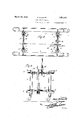
consisting in the anfobject ofthe invention-to pm j 'a greatly increased leverage "for final ad- Wi hrsu hj: biect ifl w h v bei l felted as wellfa's other advantages that may be Tiin e i initheiht t m y parts and combinationscon ituting the same ii hereinia'it orth, is understoodithat some ehaag'e s n1 arrangement f of parts may be madewithoutjdeparting from the'n'ature and-scope of the inventioniand in order to v make the invention more clearly understood there are shown in the accompanying draw invention in an operabledevicet M t Figure l is aside elevationiof be improved device. V Figure 2isap1an ofthedelvice.
x Figurefiis-an end'elevation. f
The frame work i the apparatus comM gs a preferred manner o V embodyi th 7 said smooth bores in the opposed guide members, nuts associated with said rods to bear against said guide members for holding said, frame sections ln'proper' operative relation,
with means also associated with said rods" for rotating the same for expanding or contract ing said frame sections. v
6. An apparatus for squeezing loads into cars or the like comprising a pair of rectangular frame sections, each frame section having four opposed bearing members with smooth bores therein, four spacer rods positioned through opposed bearing members,
right and left hand threads on the said rods, 7 nuts coacting with said bearing members and 7 said rods for causing said frame members to move toward or away from eachother when 1 the rods are turned, means for rotating said rods continuously and 'means for rotating said rods intermittently. 1
7 Anapparatus for squeezing loads into cars or the like comprising a pair of rectangular frame members, each frame member havfour bearing'blocks secured thereto and arranged in opposed relation when said frame members are operatively arranged, spacer rods cooperating with said bearing blocks and having threaded ends to engage with threaded meansassociated with said'bearing blocks, means for rotating said rods continua ously to move said framemembers toward or away from each other, and othermeans for rotating said rods intermittently. 1
In testimony whereof I airix my signature.
FRED STEBLER.
Priority Applications (1)
| Application Number | Priority Date | Filing Date | Title |
|---|---|---|---|
| US533349A US1851461A (en) | 1931-04-27 | 1931-04-27 | Car loading device |
Applications Claiming Priority (1)
| Application Number | Priority Date | Filing Date | Title |
|---|---|---|---|
| US533349A US1851461A (en) | 1931-04-27 | 1931-04-27 | Car loading device |
Publications (1)
| Publication Number | Publication Date |
|---|---|
| US1851461A true US1851461A (en) | 1932-03-29 |
Family
ID=24125577
Family Applications (1)
| Application Number | Title | Priority Date | Filing Date |
|---|---|---|---|
| US533349A Expired - Lifetime US1851461A (en) | 1931-04-27 | 1931-04-27 | Car loading device |
Country Status (1)
| Country | Link |
|---|---|
| US (1) | US1851461A (en) |
Cited By (2)
| Publication number | Priority date | Publication date | Assignee | Title |
|---|---|---|---|---|
| US2424768A (en) * | 1945-06-18 | 1947-07-29 | Improved Carloading Company | Car squeeze |
| US2575326A (en) * | 1947-11-19 | 1951-11-20 | Lucian N Anderson | System of freight loading and handling |
-
1931
- 1931-04-27 US US533349A patent/US1851461A/en not_active Expired - Lifetime
Cited By (2)
| Publication number | Priority date | Publication date | Assignee | Title |
|---|---|---|---|---|
| US2424768A (en) * | 1945-06-18 | 1947-07-29 | Improved Carloading Company | Car squeeze |
| US2575326A (en) * | 1947-11-19 | 1951-11-20 | Lucian N Anderson | System of freight loading and handling |
Similar Documents
| Publication | Publication Date | Title |
|---|---|---|
| US1851461A (en) | Car loading device | |
| US2693890A (en) | Loading and unloading device for vehicles | |
| US1517100A (en) | Brace for holding boxes and crates in railway cars | |
| DE3117915A1 (en) | "DEVICE FOR SHAPING A HEAT-SHRINKABLE PLASTIC FILM" | |
| SU117579A1 (en) | Tailgate body for trucks | |
| US1833569A (en) | Tie basket | |
| US3209705A (en) | Spacing and reinforcing unit for use in loading crushable containers in cargo carriers | |
| US1119585A (en) | Stock and grain rack. | |
| DE497076C (en) | Self-unloading trolleys for moist cargo | |
| DE541536C (en) | Method for loading freight vehicles, in which extensive piece goods are loaded separately onto the vehicle | |
| DE906679C (en) | Container for shipping fish or the like. | |
| DE471306C (en) | Container for wagons for transporting dust or fine-grained cargo with cargo space divided by partition walls and separate drainage funnels for each compartment | |
| US1563030A (en) | Automatic stick guide | |
| DE1946706C (en) | Boilers for transformers | |
| GB569026A (en) | Improvements in baling presses | |
| AT162176B (en) | Conveyor system. | |
| US56824A (en) | Improvement in presses for cider-mills | |
| GB620592A (en) | Improvements in devices for the unloading of goods, packing cases and the like | |
| AT118546B (en) | Cable transport roller. | |
| AT257258B (en) | Shelf for cheese wheels can be transported by means of a trolley | |
| US494267A (en) | Baling-press | |
| CH447832A (en) | Transport trolley with moveable loading shovel | |
| US311816A (en) | Cotton and hay press | |
| AT67327B (en) | Dismountable building. | |
| DE102011121232A1 (en) | Force-transforming device for rescue vehicle to lift e.g. load, has rope tensioned by roller, where device functions according to walking principle, and exhibits feature of stable equilibrium adjusted within limits when load is simulated |