US1851443A - Combination protective goggles - Google Patents
Combination protective goggles Download PDFInfo
- Publication number
- US1851443A US1851443A US242425A US24242527A US1851443A US 1851443 A US1851443 A US 1851443A US 242425 A US242425 A US 242425A US 24242527 A US24242527 A US 24242527A US 1851443 A US1851443 A US 1851443A
- Authority
- US
- United States
- Prior art keywords
- cups
- lens
- goggle
- frame
- protective
- Prior art date
- Legal status (The legal status is an assumption and is not a legal conclusion. Google has not performed a legal analysis and makes no representation as to the accuracy of the status listed.)
- Expired - Lifetime
Links
- 230000001681 protective effect Effects 0.000 title description 9
- 239000011521 glass Substances 0.000 description 10
- 238000009432 framing Methods 0.000 description 2
- 229920001342 Bakelite® Polymers 0.000 description 1
- 229920002160 Celluloid Polymers 0.000 description 1
- MWAYJIAKVUBKKP-IUCAKERBSA-N Met-His Chemical compound CSCC[C@H]([NH3+])C(=O)N[C@H](C([O-])=O)CC1=CN=CN1 MWAYJIAKVUBKKP-IUCAKERBSA-N 0.000 description 1
- 235000001484 Trigonella foenum graecum Nutrition 0.000 description 1
- 244000250129 Trigonella foenum graecum Species 0.000 description 1
- 239000004637 bakelite Substances 0.000 description 1
- 230000005494 condensation Effects 0.000 description 1
- 238000009833 condensation Methods 0.000 description 1
- 238000010276 construction Methods 0.000 description 1
- 230000007547 defect Effects 0.000 description 1
- 238000006073 displacement reaction Methods 0.000 description 1
- 229920001971 elastomer Polymers 0.000 description 1
- 210000003128 head Anatomy 0.000 description 1
- 239000000463 material Substances 0.000 description 1
- 239000002184 metal Substances 0.000 description 1
- 239000000203 mixture Substances 0.000 description 1
- 230000004048 modification Effects 0.000 description 1
- 238000012986 modification Methods 0.000 description 1
- ISWSIDIOOBJBQZ-UHFFFAOYSA-N phenol group Chemical group C1(=CC=CC=C1)O ISWSIDIOOBJBQZ-UHFFFAOYSA-N 0.000 description 1
- 108010027345 wheylin-1 peptide Proteins 0.000 description 1
Images
Classifications
-
- G—PHYSICS
- G02—OPTICS
- G02C—SPECTACLES; SUNGLASSES OR GOGGLES INSOFAR AS THEY HAVE THE SAME FEATURES AS SPECTACLES; CONTACT LENSES
- G02C7/00—Optical parts
- G02C7/02—Lenses; Lens systems ; Methods of designing lenses
Definitions
- This invention relates to protective eye goggles, and more particularly goggles suitable for eyes which also require corrective lenses; and it is among the objects of the invention to provide a' safe and accurate mounting for corrective lenses that may be required as wellas the protective or filter glasses.
- Afurther object is an improved frame construction. Other objects and ad- 1 vantages will appear as the description proceeds.
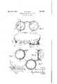
- FIG.1 is a front elevation of an embodiment of the invention
- Fig. 2 is a plan view, half in section
- Fig. 3 is a detail section taken on a plane indicated by the'line III-J11, Fig. 2
- Fig. 4 is a section taken on a plane indicated by the line IVIV, Fig. 3
- Fig. 5 is a detail in plan showing a modification
- Fig, 6 is a sectional detail taken on a plane indicated by the line VIVI, Fig. 5.
- the invention contemplates aframe, carrying lens-holding rings and protective-glass goggle cups. The.
- frame includes a bridge 2 with arms extending thence laterally and to these in turn are attached goggle cups 3 of metal, composition,
- each gogglecup a lens-holding ring 5 having a split joint 6. While such ring may be held by shoulders or suitable locking means I prefer to seat it in the cup toward the front, and further secure it against displacement by passing the screws 4 through lugs 7 extending rearwardly for that purpose.
- the protective or filter glass 9 may be positioned, as indicated, tothe front ofthecorrective lens and; i may be secured in place by a screw-threaded ring 10 engageable with the goggle cup.
- the goggles may head by. an adjustable headbandv 11, where corrective lenses of considerableparticularity are required, I contemplate the applica tion of temple bows, the framing being oar ried about the goggle cup to a lug-joint12 to which the temple bow 13 (Fig. 5) be j secured; i j
- a lens-carrying ring within i v desirably be held in position on the Wearers l each cup, top and bottom lugs extending rearwardly from said rings and engaged by said connecting screws, aiprotective glass for each ;Jcup,'and a screw ring for retaining said pro- 5 'tective'glass.
- 1 i V Y j i V 3 In aspectacle goggle, thecombination of a fran1e,-'gogg1e-cups thereon, said frame 7 a extendingabout said cups and having temple bows at the' o uter sides, screws connecting the'framete the upper and'lewer sidesipf said- I: i
Landscapes
- Health & Medical Sciences (AREA)
- Ophthalmology & Optometry (AREA)
- Physics & Mathematics (AREA)
- General Health & Medical Sciences (AREA)
- General Physics & Mathematics (AREA)
- Optics & Photonics (AREA)
- Eyeglasses (AREA)
Description
March 29, 1932. w. NUTT 155L443 COMBINATION PROTECTI VE GOGGLES Filed Dec. 24, 1927 A TTORNEYS Patented Mar. 29, 1932 umrsnsrras BUELL w. norm, or LAKnwoon onIo, -essreiron"'rojrnn snrrz'rr. neurriuitivzrif, SERVICE coMrAnY, or cLnvELANn-,;on'm; A oonroaamrono OHIO s COMBINATION rnornorlvn eoeenns r Application filed December 24,1927. Serial No. 242,425. [j T, l
This invention relates to protective eye goggles, and more particularly goggles suitable for eyes which also require corrective lenses; and it is among the objects of the invention to provide a' safe and accurate mounting for corrective lenses that may be required as wellas the protective or filter glasses. Afurther object is an improved frame construction. Other objects and ad- 1 vantages will appear as the description proceeds. Q V
To the accomplishment of the foregoing and related ends, the invention, then, consists of the features hereinafter fully described,
and particularly pointed out in the claims, the following descriptionand the annexed drawings setting forth in detail certain structures embodying the invention, such being illustrative however of but a few of the various ways in which the principle of the invention may be employed.
In said annexed drawings Fig.1 is a front elevation of an embodiment of the invention;Fig. 2 is a plan view, half in section; Fig. 3 is a detail section taken on a plane indicated by the'line III-J11, Fig. 2; Fig. 4 is a section taken on a plane indicated by the line IVIV, Fig. 3; Fig. 5 is a detail in plan showing a modification and Fig, 6 is a sectional detail taken on a plane indicated by the line VIVI, Fig. 5.
In its general aspects, the invention contemplates aframe, carrying lens-holding rings and protective-glass goggle cups. The.
frame includes a bridge 2 with arms extending thence laterally and to these in turn are attached goggle cups 3 of metal, composition,
bakelite or other phenolic condensation prod-' uct, rubber, celluloid or other material as desired, preferably screws 4 being passed through the framing and the cups. Within each gogglecup is a lens-holding ring 5 having a split joint 6. While such ring may be held by shoulders or suitable locking means I prefer to seat it in the cup toward the front, and further secure it against displacement by passing the screws 4 through lugs 7 extending rearwardly for that purpose. In this manner a secure anchorage of the lens ring f may be had, and yet allow of disassemblage conven'iently for the placement or change i of a lens thecorrectivelensesfi irequisiteifor y p li la rease h e-t u pe d spectacle usageff'ihe rings or ringgroovesl needgnotfbe limited toj 'one, andarplurality of corrective lenses, or correct ve and protective glasses maybereadily mounted; and in;
some instances 1' may 'more-simply' hold a the v glassesby-rings compressed or swea-ted intoclose frictionalengagement. The protective or filter glass 9 may be positioned, as indicated, tothe front ofthecorrective lens and; i may be secured in place by a screw-threaded ring 10 engageable with the goggle cup.
While in manyinstances, the goggles may head by. an adjustable headbandv 11, where corrective lenses of considerableparticularity are required, I contemplate the applica tion of temple bows, the framing being oar ried about the goggle cup to a lug-joint12 to which the temple bow 13 (Fig. 5) be j secured; i j
Itwill-thus be seen that correctivelenses may be accurately and conveniently carried in conjunction with protective or filter glasses and in a manner allowing of ready disassem- I blage for changes at anytime and avoiding the handicap heretofore customary in the case of protective goggle usershaving inherent defects of'vision. V
Other modes of applying the principle of the invention may be employed, change being L made as regards the details disclosed, provided the means stated in any of the following claims, or the equivalent of such, be employed. v
' I therefore particularly point outand distinctly claim as my invention 1. In a spectacle goggle, the combination of a frame, gogglecup's thereon, screws connecting the frame to the upper and lowerjsides of said cups, a lens-carrying ring within each cup, and top and bottom lugs extending rear wardly from said rings andengaged by said connecting screws." 7' i i 2. In a specta'clegoggle, the COIIlblIlELtlOIIY of a frame, goggle-cups thereon, screwsjcom necting the frame 'to the upper and lower,
sides of said cups, a lens-carrying ring within i v desirably be held in position on the Wearers l each cup, top and bottom lugs extending rearwardly from said rings and engaged by said connecting screws, aiprotective glass for each ;Jcup,'and a screw ring for retaining said pro- 5 'tective'glass. 1 i V Y j i V 3. In aspectacle goggle, thecombination of a fran1e,-'gogg1e-cups thereon, said frame 7 a extendingabout said cups and having temple bows at the' o uter sides, screws connecting the'framete the upper and'lewer sidesipf said- I: i
7 cups, a lensscarrying ring within eachvmip, I a
and a protective glass in front of said lens rings i 4. In a spectacle goggle, the cornbinatien 15 OH frame, g gg e-'cu s-thereoii, said frame extending about said cups and having tern ple bows at the outer sides, screw s connecting the frame to'the' upp'erand lcwersi des of said cups, a lens-carrying ring within e ach:cup,' a
7 o protective glass in front of said lens ring; and
av screw ringuforrretaining saidhprotectiye j'glass V i I Signed by methis 22nd day o f December,
15192 7. I h 7 r BUELL W. NU T;
Priority Applications (1)
| Application Number | Priority Date | Filing Date | Title |
|---|---|---|---|
| US242425A US1851443A (en) | 1927-12-24 | 1927-12-24 | Combination protective goggles |
Applications Claiming Priority (1)
| Application Number | Priority Date | Filing Date | Title |
|---|---|---|---|
| US242425A US1851443A (en) | 1927-12-24 | 1927-12-24 | Combination protective goggles |
Publications (1)
| Publication Number | Publication Date |
|---|---|
| US1851443A true US1851443A (en) | 1932-03-29 |
Family
ID=22914741
Family Applications (1)
| Application Number | Title | Priority Date | Filing Date |
|---|---|---|---|
| US242425A Expired - Lifetime US1851443A (en) | 1927-12-24 | 1927-12-24 | Combination protective goggles |
Country Status (1)
| Country | Link |
|---|---|
| US (1) | US1851443A (en) |
Cited By (2)
| Publication number | Priority date | Publication date | Assignee | Title |
|---|---|---|---|---|
| US2761145A (en) * | 1952-11-26 | 1956-09-04 | Chicago Eye Shield Company | Goggle assembly |
| US3261652A (en) * | 1962-07-18 | 1966-07-19 | Finn H Magnus | Adjustable temple for eyeglasses with rack and plural detent bar |
-
1927
- 1927-12-24 US US242425A patent/US1851443A/en not_active Expired - Lifetime
Cited By (2)
| Publication number | Priority date | Publication date | Assignee | Title |
|---|---|---|---|---|
| US2761145A (en) * | 1952-11-26 | 1956-09-04 | Chicago Eye Shield Company | Goggle assembly |
| US3261652A (en) * | 1962-07-18 | 1966-07-19 | Finn H Magnus | Adjustable temple for eyeglasses with rack and plural detent bar |
Similar Documents
| Publication | Publication Date | Title |
|---|---|---|
| US5184231A (en) | Helmet systems | |
| US1851579A (en) | Binocular nose glasses | |
| US2280354A (en) | Binoculars | |
| US8136946B2 (en) | Apparatus for determining prescription for prism lenses for diplopic patients | |
| US1851443A (en) | Combination protective goggles | |
| US2112644A (en) | Goggles | |
| US2388713A (en) | Adjustable lens mount for gas masks | |
| US3577566A (en) | Spectacle hood | |
| US1892444A (en) | Telescopic goggles | |
| US701788A (en) | Binocular magnifying-glass. | |
| US276732A (en) | Optometer | |
| US2233689A (en) | Apparatus for developing visual fusion | |
| US1628551A (en) | Antiglare device | |
| US8123355B2 (en) | Apparatus for determining prescription for reading lenses for eyes with mild AMD | |
| US2075020A (en) | Goggles, spectacles, or the like | |
| US1471996A (en) | Spectacles | |
| US1530240A (en) | Means, such as lenses, for spectacles and eyeglasses for assisting or correcting defective vision | |
| US1712360A (en) | Spectacles | |
| US2386998A (en) | Eyeglasses | |
| US980070A (en) | Bifocal testing-frame. | |
| US786442A (en) | Attachment for spectacles. | |
| US1635062A (en) | Binocular magnifying-lens holder | |
| US498019A (en) | Mirror attachment for opera-glasses | |
| US291778A (en) | Spectacles | |
| US1943387A (en) | Optical aiming-device for machine guns |