US1851441A - Yarn and method of making the same - Google Patents
Yarn and method of making the same Download PDFInfo
- Publication number
- US1851441A US1851441A US104038A US10403826A US1851441A US 1851441 A US1851441 A US 1851441A US 104038 A US104038 A US 104038A US 10403826 A US10403826 A US 10403826A US 1851441 A US1851441 A US 1851441A
- Authority
- US
- United States
- Prior art keywords
- yarn
- strand
- strip
- paper
- twisting
- Prior art date
- Legal status (The legal status is an assumption and is not a legal conclusion. Google has not performed a legal analysis and makes no representation as to the accuracy of the status listed.)
- Expired - Lifetime
Links
- 238000004519 manufacturing process Methods 0.000 title description 34
- 239000000463 material Substances 0.000 description 57
- 239000010425 asbestos Substances 0.000 description 47
- 229910052895 riebeckite Inorganic materials 0.000 description 47
- 239000004744 fabric Substances 0.000 description 16
- 230000003014 reinforcing effect Effects 0.000 description 15
- 238000000034 method Methods 0.000 description 10
- 241001589086 Bellapiscis medius Species 0.000 description 9
- 229920000742 Cotton Polymers 0.000 description 7
- 239000005418 vegetable material Substances 0.000 description 5
- 239000000835 fiber Substances 0.000 description 4
- XLYOFNOQVPJJNP-UHFFFAOYSA-N water Substances O XLYOFNOQVPJJNP-UHFFFAOYSA-N 0.000 description 4
- 238000004804 winding Methods 0.000 description 4
- 230000005540 biological transmission Effects 0.000 description 3
- 235000013311 vegetables Nutrition 0.000 description 3
- 210000005069 ears Anatomy 0.000 description 2
- 230000000694 effects Effects 0.000 description 2
- 229920002472 Starch Polymers 0.000 description 1
- 230000015572 biosynthetic process Effects 0.000 description 1
- 238000010276 construction Methods 0.000 description 1
- 238000002425 crystallisation Methods 0.000 description 1
- 230000008025 crystallization Effects 0.000 description 1
- 238000010438 heat treatment Methods 0.000 description 1
- 229910052573 porcelain Inorganic materials 0.000 description 1
- 238000005096 rolling process Methods 0.000 description 1
- 238000007493 shaping process Methods 0.000 description 1
- 235000019698 starch Nutrition 0.000 description 1
- 239000008107 starch Substances 0.000 description 1
- 239000000725 suspension Substances 0.000 description 1
Images
Classifications
-
- D—TEXTILES; PAPER
- D02—YARNS; MECHANICAL FINISHING OF YARNS OR ROPES; WARPING OR BEAMING
- D02G—CRIMPING OR CURLING FIBRES, FILAMENTS, THREADS, OR YARNS; YARNS OR THREADS
- D02G3/00—Yarns or threads, e.g. fancy yarns; Processes or apparatus for the production thereof, not otherwise provided for
- D02G3/02—Yarns or threads characterised by the material or by the materials from which they are made
- D02G3/16—Yarns or threads made from mineral substances
- D02G3/20—Yarns or threads made from mineral substances from asbestos
Definitions
- This invention relates to yarn, fabric, and a method of and apparatus for manufacturing such yarn, and relatesmore particularly to the manufacture of yarn and fabric in which use is made of paper or paper-like material, preferably formed of asbestos material bound together with suflicient cohesiveness and tenacity for and adapted for yarn manufacture.
- the invention relates to the manufacture of yarn adapted fordifferent uses but having particular utility in friction, wear and heat resisting fabrics suitable, for example, for use in brake linings, transmission linings, clutch facings, etc.
- the invention relates more particularly to the manufacture of yarn from asbestos paper or paper-like material which is difiicult to handle properly during the various steps of manufacture.
- asbestos material into paper or paper-like material and after forming the paper or paper-like material to separate the same into strips of suitable width and to form said strips into flat rolls, Then each in softened or moistened condition, is drawn preferably from the center of the corresponding flat roll under low tension and twisted with one or more supporting or reinforcing filaments combined with the strip one at a time or more than one at a time.
- An important object of the invention is to provide a method of making yarn having advantageous characteristics for various purposes, such as those specified.
- a method of making yarn including twisting a strip of such paper-like material with, a core thread of vegetable'fibre, wrapping the twisted elements with a second thread of material by twisting in the same direction, and untwisting the three twisted elements to relieve the tension on the strip, and at the same time twisting said elements with a reinforcing element.
- an improved yarn of the character specified an asbestos yarn or yarn element formed of one or more paper-like strips or hands of asbestos material in substantially untwisted condition associated with one or more longitudinal filaments and secured thereto by one or more binding filamentsan asbestos yarn formed of asbestos'paper-like material in substantially untwisted form arranged about a core and bound thereto by helically arranged filaments; an asbestos yarn formed from asbestos paper-like strip and including a filament relatively near the axis of the yarn and a plurality of filaments" two intertwined core filaand a.
- friction and heat resisting fabric or the like containing yarn formed from asbestos paper-like material with two twisted strands near the axis of the yarn and separated by the paper-like material and having one or more filaments twined together, arranged helically around the yarn and embedded in the surface of the yarn.
- Another important object of the invention is to provide improved yarn making appara'v tus which may be used for carrying out the process of the invention.
- Other objects of the invention are to provide means for imparting uniformity of cross section and of twist and to provide means to effect an operation of twisting two wires together and arranging them helically about the body of the yarn.
- Fig. 1 is a view illustrating twisting mechanism and mechanism for supporting and feeding yarn elements to the twisting mechanism in the first step of the process;
- Fig. 2 is a view illustrating mechanism employed in carrying out the second step of the process
- Fig. 3 is a view illustrating apparatus em: ployed in the third step'of the process
- Fig. 4 is a view of a short len th of the preliminary yarn or roving as obtained at the end of the second operation
- Fig. 5 is a view of ashortlength of the
- Fig. 6 is a section, on a somewhat larger scale, of the yarn shown in Fig. 5;
- Fig. 7 is a conventional plan view of fabric made from such yarn
- Fig. 8 is a conventional sectional view of the fabric of Fig. 7;
- Fig. 9 is a detail view of the tension apparatus of Fig. 1;
- Fig. 10 is a section on the line 1010 of I referably the paper or paper-like material is made from asbestos material containing asbestos fibre of any available or suitable length and bound together with sufficient coheslveness and tenacity for and adapted for yarn manufacture.
- the asbestos material is formed into a pulp and mixed with binding material comprising materialsuch as starch, which is generally water soluble or which may be softened by water and by use of a suflicient amount thereof may be brought into colloidal suspension.
- the asbestos material and binding material is then formed into asbestos paper or paper-like material which may be bound together with suflicient cohesivenessand tenacity to undergo strand and yarn forming operations.
- asbestos paper or paper-like stantially the same as described in my material is used in the form of strips or bands which may be obtained by slitting the paper-like sheet or web into strips or bands and rolling such strips or bands into flat rolls.
- FIG. 1 of the drawings I have shown apparatus similar to that disclosed in my co-pending application, Serial No. 21,087, filed: April 6, 1925, Patent No. 1,585,625 which is here used for supporting spools of material such as cotton thread and moistened rolls of asbestos strip material, for uniting the threads and strip material at predetermined points, and for guiding the united elements into a twisting devicel.
- Fixed to a plurality of standards, one of which is shown at 2 are a plurality of cross beams or bars 3, 4, 5 and 6, from which the various spools and guides are supported.
- pins 7 and 8 Projecting perpendicularly from the inclined front face of the beams 3 are pins 7 and 8 on which are placed spools 10 and 11 which carry, respectively, cords or threads 12 and 13, preferably of cotton.
- the thread 12 passes through a guide 14 to the upper end of a clamping or tension device 15 which serves to retard the movement of the thread and exert a suflicient degree of tension thereon to maintain the same free of knots or undesirable twists.
- This clamping or tension device may be subd sa1 application, Serial No. 21,087, Patent No. 1,585,625.
- the strand 12 is led through a guide 16 of suitable material, such as porcelain, supported from the beam 5, and is combined at this point with an asbestos strip 17 and then passed through a friction cylinder 18 supported by the beam 6 where it is combined with the cotton strand 13 and is fed into the twister 1.
- the asbestos strip 17 is provided preferably in the form of a flat roll 20, which has been moistened by immersing it for a suitable period of time in a tankcontaining water, and is supported by a tray 21 extendinghorizontally from the standardof the supporting frame intermediate the beams 5 and 6 in sucha position as to permit feedingof thestripfrom the center of the roll to 'and through three ,guides 22, 23 and 24, in the orderm'entioned.
- the intermediate. guide .23 is mounted on the lower end of an arm 25 pivoted,-as in dicated in my said co-pendi-ng application, Serial N 0. 21,087, Patent; No. 1,585',625.to the beam 5, thus permittingEthe-guide 23,,to be shifted to and fromthe line throughg the ly been moistened to modify being necessary to other guides to vary the tension of the strip.
- the arm may be held, as by friction at the pivot, in any position to which it is shifted to give the tension required.
- the strip 17 is needled through these guides or, if the strip is of insufficient tensile strength, through two or only one of these guides and thence into the axial guide or eye 16 where it is associated with the filament or core 12.
- Tray 21 may preferably be provided with an upstanding rim 26 to prevent the flow therefrom of the water from the moistened paper-like material of the rolls 20, which, as hereinbefore stated, had previousmaterial and permit easier working thereof during the twisting operations.
- the second cord 13, preferably cotton thread, is led from the spool 11 adjacent to spool 10 through a tension device 27, the strand being guided at the top of the tension device by a guide 28 and at the bottom of the tension device by a guide 29, such guiding maintain the cord 13 in its proper direction through the tension device 27 and to prevent the cord from being drawn to one side by the inclined stretch thereof extending toward the twister].
- the cord 13 Fromthe guide 29, the cord 13 passes in an inclined direction to and through an eye30 on the end of an arm 31 fixed to the beam 6, and from the eye 30 the filament passes into the friction cylinder 18 where it is combined with the strand 32 formed of the cord 12, and the asbestos paper strip 17. It should be understood that the friction cylinder 18 tends to regulate the twist, to render the product more uniform, and to assist in applying the thread 13 to the strand 32.
- a pulley 34 secured thereto near its upper end, and at its lower end a cross mem- From the sleeve 33 the yarn is passed around a pulley 36 on the member 35, and then woundback and forth around shafts 37 and 38 journaled in the cross member 35.
- a winding sleeve 39 car-. rying at its npper'en-d a pulley 40 and at its lower end a gear 41, sleeve 39-being supported in a bracket 42.
- the gear 41 at the lower end of the sleeve 39 engages gears 43 and 44.
- the cotton threads or cords 12 and 13 are of two or more plies, and each cord has a twist, preferably to the left when the thread 12 and strip are twisted together in the direction to give a right hand twist.
- right hand twist is meant a twist in the yarn to produce a clockwise direction of the strands from the point of view of an observer looking along the yarn axis.
- a left hand twist is the reverse.
- the thread 12 and the strip 17 are, as herein disclosed, twisted together to give three twists to the inch to the right, and starting at the upper end of the cylinder 18 are twisted with the cotton thread 13 which is wrapped around the strand 32,
- the resulting strand 46 being wound on spool or yarn 46, resulting from the first operation is removed from the spindle 53 after lifting the latter out of its bearing 54 and placed on an inclined'pin 64 projecting from a beam, corresponding to the upper beam 3 of the 1, and the strand 46 is passed downwardly from the spool through a guide 65 just above 66, corresponding to tentaining the strand sion devices 15 and 27, From the tension device, the strand 46 passes downwardly to a point where it is deflected, to'someextent, by means including a supporting rod 68 mounted'at one end on a beam correspond-'ng to the beam 6.
- the rod 68 At its free end the rod 68 is provided with an open eye- 69 through which the strand 46 passes and beneath which" it is united with one or more filaments, such as wires 70, drawn from spools 7-1 mounted on inclined pins, so as to produce tension on the wires 70 when drawn from spools 71.
- the two wires 70 are slightly frame shown in Figure.
- the preliminary twist of the wires 7 0 before reaching the twister 73 is due to the running back of the twist from the twister and such preliminary twist begins at a point which may depend upon the horizontal distance apartof the spools 71 or upon an eye or guide by which the wires are brought together. By combining the parts in this manner there is less liability of crystallization of the wires and the wires are associated in a better manner with the other yarn material.
- the preliminary twist of the wires 70 assures the location of the wires together in the strand or roving 74 and in the final yarn.
- the tension devices 15 and 27 are preferably of the same construction and, for convenience, the description will be limited to device 15 which includes a suitable bracket 7 6 having an arm fixed to the beam 4, a plate 77 provided with a plurality of alternate narrow slots 78 and raised bars 79 extending across the path of the thread or filament 12; and a cooperating slotted plate 80 having raised bars 81 arranged to enter the slots 78 in the plate 77.
- the plates 77 and 80 are From the point of en agement with the eye- '69, however, down to the point where it enters provided respectively with ears 77 and 80' by means of which the plates are pivotally attached to the bracket 76, the ears 80' ex-' tending rearwardly and by engagement with the bracket 76 limiting the rearward movement of plate 77.
- a lever 83 pivoted on .the bracket 7 6 and having at its outerend a weight 84 and at its inner end a contact shoe 85 pivoted on lever 83 at 86 and adjustably held in position by means of a set screw 87 passing through a slot in said shoe 85.
- the shoe 85 engages the plate 77 and by adjusting the shoe 85, the lever effect of the weight 84 on the plate 77 may be varied.
- the operations may be carried out advantageously in the following manner.
- the resulting strand was given approximately three twist-s to the inch to the right, thereby tending to untwist the threads or cords 12 and 13, and in the second operation, the resulting strand is given approximately three twists to the inch to the left, thereby tightening the twist of threads 12 and 13 and associating them more thoroughly with the strip 17.
- the strand 46 leaves the spool 52 down to the point where it frictionally engages eye 69, there is substantially no twisting of this yarn, that is, it-retains approximately the same number of twists as was given the strand 46 resulting from the first operation.
- this yarn receives approximately three twists to the left per inch. This twisting tends to restore the twist of the threads 12 and 13 and to combine the strip 17 and threads more thoroughly than would be the case without the preliminary untwisting of the threads.
- the paper in the strand or roving 74 resulting from the second operation will have no twist.
- the wires or filaments pass from spools 71 to the point'where the strand enters the friction cylinder 72 and the filaments or wires are then twisted three times to the left around the modified strand 46. There is obtained then at this stage, a strand, roving or preliminary yarn 74 in which the paper has no twist and the wires have three twists to the left per inch around the yarn.
- the preliminary yarn 74 which has been wound upon the spool 7 5 at the end of the second operation' is removed from the twister 73, and the spool is placed on a pin 88 mounted in inclined position on the upper beam of a frame, such as shown in Fig. 1, the roving or preliminary yarn then being led downwardly to a twister 89 by which the yarn 74 is given three additional twists to the left, thus producing a yarn 90 having six twists of the wires or filaments to the left and three twists of the paper to the left.
- the third operation may consist in giving the yarn 74 any number of final twists, depending upon the requisites of the trade'and the kind of yarn desired. It should be understood that the original twisting may be either to the right or to the left, and the reversal in the twisting may be obtained in the later operations. It should also be understood that as a result of the preliminary untwisting of the threads 12 and 13, they are not so tightly twisted in the final yarn, and that as a result of this and the twisting and untwisting of the strip 17, the final yarn is softer and therefore more useful for certain purposes than would otherwise be the case.
- the number of twists given to the yarn determines the strength and quality of the finished product, according to commercial re quirements, and is an important factor in de termining the quality of fabric made from the yarn. It should be understood that various changes may be made in the strands, rovings and yarns without departing from the true spirit and scope of the invention.
- the yarn of the present invention is particularly adapted for use in the manufacture of fabrics for use, for example, in brake lining's, transmission linings and clutch facings.
- the showing in Figs. 7 and 8 of a fabric having warp yarn 91 and weft yarn 92 is merely conventional and that in actual practice the yarns are woven or otherwise utilized in different ways to obtain fabrics having the proper thickness, closeness of texture and other qualities required.
- fabrics are made of several plies or of thickness to correspond to that of usual multi-ply fabrics.
- asbestos material wherever it appears in the specification and claims, is intended to refer to material having a substantial percentage of asbestos fibres, such as to give more or less the characteristics of asbestos as far as working and handling are concerned, and the term I asbestos material, where used in the specification and claims shall be considered as thus defined.
- a method of'making yarn which includes twisting a paper-like strip with a filament, arranging a thread helically therearound and reversing the twist to provide slack in the paper strip and form a suitable strand.
- a method of making yarn which includes twisting a paper-like'strip with a core filament and a binding filament, and reversing the twist to provide slack in the paper strip and form a strand.
- a method of making cludes associating a paper-like strip helically with a tension filament and a binding filament for support thereby, and twisting the product thus formed in a direction to provide slack in the strip and produce a strand.
- a method of making yarn from a strand comprising a. paper-like strip arranged helically around a core and bound thereto by a helically arranged binding filament, which includes the step of twisting said strand to provide slack in said paper-like strip.
- a method of making yarn from a strand comprising a paper-like strip arranged helically around a core and bound thereto by a binding filament having a similar helical ararn which inrangement, which includes the step of twisting said strand in a direction to provide slack ing filament.
- a method 'of making yarn which includes twisting in a given direction a strip of asbestos paper and a strand of vegetable fibre, arranging helically therearound a strand of vegetable fibre, twisting the product with a reinforcing filament in'the opposite direction to take the twist out of said strip, and further twisting the product so formed in such opposite direction to the extent required.
- a method of making yarn which includes twistingtogether in a given direction a paper strip with a twisted strand, winding therearound a second twisted strand, twisting twined reinforcing filaments with the paper strip and twisted strands in a ditwisting in such opposite direction the pre-' liminary yarn to form a final yarn.
- a method of making yarn including twisting a paper strip with a core of vegetable material, wrapping a thread of vegetable material therearound, reversing the twist to relieve the tension of the paper strip and form a suitable strand, and concomitantly twisting with such reverse twist the strand with a reinforcing filament.
- a method of making yarn which includes forming a strip or band of asbestos material unitedwith binding material, moistening the strip to soften the same, twisting the strip with supporting threads, twisting the strip and threads with a reinforcing filament in the opposite direction to form a preliminary yarn, and thereafter twisting the preliminary yarn to a greater extent to form a final yarn.
- a method of making yarn including twisting a strip of asbestos paper with a thread core, wrapping the twisted elements with a second thread by twisting in the same direction, reversely twisting the three twisted elements to relieve the tension on the strip, and concomitantly twisting said elements with a reinforcing element to form a preliminary yarn, and tightly twisting the preliminary yarn thus formed with said reinforc-' ing element in such reverse twist direction to form a final yarn.
- a method of making yarn including supporting a strip of asbestos paper by combining the same with a thread, relieving the tension, on said strip, and combining the strand thus formed with a reinforcing filament to impart sufiicient tensile strength to the yarn.
- A-method of making asbestos yarn from a strip or band of asbestos material united by binding material which includes twisting the strip with a thread in a direction to untwist the thread, twisting a second thread around the first thread and the strip by a twist in the same direction, and twisting the two threads and the strip with a filament in the opposite direction to leave the strip substantially without twist.
- a method of making yarn which includes twisting together in a given direction a strand having the opposite twist and a strip of asbestos material united by binding material, winding therearound a second strand having said opposite twist, twisting two reinforcing filaments together in the direction opposite to said given direction, twisting the twisted reinforcing filaments with the strip or band and twisted strands in such opposite direction to take the twist out of the strip or band and form a preliminary yarn, and subsequently tightly twisting in such opposite direction the preliminary yarn to form a final yarn.
- a method of making asbestos yarn including twisting a strip of asbestos paperlike material with a twisted core of vegetable material, wrapping ther earound a thread of vegetable material, reversing the twist to relieve the tension of the strip and form a strand, and concomitantly twisting with such reverse twist the strand with a plurality of twined wires. 16. The method of making yarn from" asbestos paper-like material united by binding material, which includes twisting the paper-like material in one direction, and then twisting said paper-like material and a filament in the opposite direction to form a strand.
- An asbestos yarn formed from a papersupporting and like strip of asbestos material united by binding material, two intertwisted core filaments separated by said asbestos material, and a plurality of twisted wires arranged helically around said asbestos-material.
- a method of making asbestos yarn which includes moistening paper-like strips of asbestos material united by binding material, associating core filaments with such moistened strips to form a strand in which said core filaments are encased by said strips, and associating said strand with binding filaments to form a yarn in which the paper-like strips of material in substantially untwisted form are bound to the core filaments by the binding filaments in helical arrangement.
- a method of making yarn which includes moistening a paper-like strip or band of asbestos material united by binding material, twisting in a given direction said strip or band and a thread already twisted in the opposite direction, twisting in the same direction the product thus formed and a second thread twisted in the same direction as the first mentioned thread to form a strand, and twisting two reinforcing filaments together in the direction of twist opposite to that used in the formation of the strand and then twisting them in such opposite direction with the strand to such an extend as to leave said strips without twist.
- the method of making yarn which includes twisting a paper-like strip of asbestos material with a filament to form a strand, reversing the twist to provide slack in the paper-strip, and concomitantly combining said strand during such reverse twist with at least one reinforcing filament.
- a method of making yarn from a strand comprising a paper-like strip of asbestos material hel'ically combined with one or more filaments which includes the steps of slackening the paper-like strip in said strand, twining a plurality of reinforcing filaments, and concomitantly combining said strand during such slackening with said twined reinforcing filaments to forma preliminary yarn.
- the method of making yarn which comprises the steps of combining a filament with asbestos paper-like material to form a strand, passing said strand through a stationary shaping and guiding cylinder, and subsequently combining the elements of said strand with an additional filament to form a yarn.
Landscapes
- Engineering & Computer Science (AREA)
- Mechanical Engineering (AREA)
- Textile Engineering (AREA)
- Yarns And Mechanical Finishing Of Yarns Or Ropes (AREA)
Description
' March 29, 1932. 'w NANFELDT YARN AND METHOD OF MAKING THE SAME Filed April 23, 1926 2 Sheets-Sheet W w l/ll/AAAAAWA hrm/ar Mum/v MA/ra 0r March 29, 1932. w NANFELDT 1,851,441
YARN AND METHOD OF MAKING THE SAME Filed April 23, 1926 2 Sheets-Sheet 2 mum/0r mum/v NAN/Z207 WWW . strip, preferably Patented Mar. 29, 1932 PATENT OFFICE WILLIAM NANFELDT,
F PATERSON, NEW JERSEY, ASSIGNOR TO WORLD BESTOS COR- PORATION, OF PATERSON, NEW JERSEY, A CORPORATION OF DELAWARE YARN AND METHOD OF MAKING THE SAME Application filed a rn'aa,
This invention relates to yarn, fabric, and a method of and apparatus for manufacturing such yarn, and relatesmore particularly to the manufacture of yarn and fabric in which use is made of paper or paper-like material, preferably formed of asbestos material bound together with suflicient cohesiveness and tenacity for and adapted for yarn manufacture.
This application is a continuation in part of each of my co-pending applications Serial No. 21,087, filed: April 6, 1925, Patent No. 1,585,625; Serial No. 23,777, filed: April 17, 1925, Patent No. 1,585,626; and Serial No.
- 67,399, filed: November 6, 1925. v
More specifically the invention relates to the manufacture of yarn adapted fordifferent uses but having particular utility in friction, wear and heat resisting fabrics suitable, for example, for use in brake linings, transmission linings, clutch facings, etc.
The invention relates more particularly to the manufacture of yarn from asbestos paper or paper-like material which is difiicult to handle properly during the various steps of manufacture. Heretofore it has been proposed to form asbestos material into paper or paper-like material and after forming the paper or paper-like material to separate the same into strips of suitable width and to form said strips into flat rolls, Then each in softened or moistened condition, is drawn preferably from the center of the corresponding flat roll under low tension and twisted with one or more supporting or reinforcing filaments combined with the strip one at a time or more than one at a time. There may be one twisting operation or a plurality of successive twisting operations.
An important object of the invention is to provide a method of making yarn having advantageous characteristics for various purposes, such as those specified.
' Other objects of the invention are to provide a method of making yarn in which a paper-like strip, preferably formed from asbestos material, is twisted with one or more filaments after being supported and twisted in the opposite direction so that after twist vegetable @926. Serial No. 104,038.
combining the same with a thread of vegetable material, relieving the tension on said strip, and combining the product thus formed with one or more reinforcing filaments to impart suflicient tensile strength to the yarn; a method of making yarn including twisting a strip of such paper-like material with, a core thread of vegetable'fibre, wrapping the twisted elements with a second thread of material by twisting in the same direction, and untwisting the three twisted elements to relieve the tension on the strip, and at the same time twisting said elements with a reinforcing element.
Further objects of the invention are to provide an improved yarn of the character specified; an asbestos yarn or yarn element formed of one or more paper-like strips or hands of asbestos material in substantially untwisted condition associated with one or more longitudinal filaments and secured thereto by one or more binding filamentsan asbestos yarn formed of asbestos'paper-like material in substantially untwisted form arranged about a core and bound thereto by helically arranged filaments; an asbestos yarn formed from asbestos paper-like strip and including a filament relatively near the axis of the yarn and a plurality of filaments" two intertwined core filaand a. friction and heat resisting fabric or the like containing yarn formed from asbestos paper-like material with two twisted strands near the axis of the yarn and separated by the paper-like material and having one or more filaments twined together, arranged helically around the yarn and embedded in the surface of the yarn.
Another important object of the invention is to provide improved yarn making appara'v tus which may be used for carrying out the process of the invention. Other objects of the invention are to provide means for imparting uniformity of cross section and of twist and to provide means to effect an operation of twisting two wires together and arranging them helically about the body of the yarn.
. -Various other objects of the invention relate to matter bearing upon details of the process, product, and apparatus such as will appear hereinafter and upon reference to the accompanying drawings, in which:
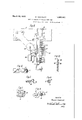
Fig. 1 is a view illustrating twisting mechanism and mechanism for supporting and feeding yarn elements to the twisting mechanism in the first step of the process;
Fig. 2 is a view illustrating mechanism employed in carrying out the second step of the process;
Fig. 3 is a view illustrating apparatus em: ployed in the third step'of the process;
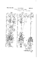
Fig. 4 is a view of a short len th of the preliminary yarn or roving as obtained at the end of the second operation;
Fig. 5 is a view of ashortlength of the,
I completed yarn;
Fig. 6 is a section, on a somewhat larger scale, of the yarn shown in Fig. 5;
Fig. 7 is a conventional plan view of fabric made from such yarn;
Fig. 8 is a conventional sectional view of the fabric of Fig. 7;
Fig. 9 is a detail view of the tension apparatus of Fig. 1; and
Fig. 10 is a section on the line 1010 of I referably the paper or paper-like material is made from asbestos material containing asbestos fibre of any available or suitable length and bound together with sufficient coheslveness and tenacity for and adapted for yarn manufacture. Preferably the asbestos material is formed into a pulp and mixed with binding material comprising materialsuch as starch, which is generally water soluble or which may be softened by water and by use of a suflicient amount thereof may be brought into colloidal suspension. The asbestos material and binding material is then formed into asbestos paper or paper-like material which may be bound together with suflicient cohesivenessand tenacity to undergo strand and yarn forming operations.
referably the asbestos paper or paper-like stantially the same as described in my material is used in the form of strips or bands which may be obtained by slitting the paper-like sheet or web into strips or bands and rolling such strips or bands into flat rolls.
Referring to Fig. 1 of the drawings, I have shown apparatus similar to that disclosed in my co-pending application, Serial No. 21,087, filed: April 6, 1925, Patent No. 1,585,625 which is here used for supporting spools of material such as cotton thread and moistened rolls of asbestos strip material, for uniting the threads and strip material at predetermined points, and for guiding the united elements into a twisting devicel. Fixed to a plurality of standards, one of which is shown at 2, are a plurality of cross beams or bars 3, 4, 5 and 6, from which the various spools and guides are supported. Projecting perpendicularly from the inclined front face of the beams 3 are pins 7 and 8 on which are placed spools 10 and 11 which carry, respectively, cords or threads 12 and 13, preferably of cotton. The thread 12 passes through a guide 14 to the upper end ofa clamping or tension device 15 which serves to retard the movement of the thread and exert a suflicient degree of tension thereon to maintain the same free of knots or undesirable twists. This clamping or tension device may be subd sa1 application, Serial No. 21,087, Patent No. 1,585,625.
Below the tension device 15 the strand 12 is led through a guide 16 of suitable material, such as porcelain, supported from the beam 5, and is combined at this point with an asbestos strip 17 and then passed through a friction cylinder 18 supported by the beam 6 where it is combined with the cotton strand 13 and is fed into the twister 1. The asbestos strip 17 is provided preferably in the form of a flat roll 20, which has been moistened by immersing it for a suitable period of time in a tankcontaining water, and is supported by a tray 21 extendinghorizontally from the standardof the supporting frame intermediate the beams 5 and 6 in sucha position as to permit feedingof thestripfrom the center of the roll to 'and through three , guides 22, 23 and 24, in the orderm'entioned.
The intermediate. guide .23 is mounted on the lower end of an arm 25 pivoted,-as in dicated in my said co-pendi-ng application, Serial N 0. 21,087, Patent; No. 1,585',625.to the beam 5, thus permittingEthe-guide 23,,to be shifted to and fromthe line throughg the ly been moistened to modify being necessary to other guides to vary the tension of the strip. Obviously-the arm may be held, as by friction at the pivot, in any position to which it is shifted to give the tension required. The strip 17 is needled through these guides or, if the strip is of insufficient tensile strength, through two or only one of these guides and thence into the axial guide or eye 16 where it is associated with the filament or core 12. Tray 21 may preferably be provided with an upstanding rim 26 to prevent the flow therefrom of the water from the moistened paper-like material of the rolls 20, which, as hereinbefore stated, had previousmaterial and permit easier working thereof during the twisting operations.
The second cord 13, preferably cotton thread, is led from the spool 11 adjacent to spool 10 through a tension device 27, the strand being guided at the top of the tension device by a guide 28 and at the bottom of the tension device by a guide 29, such guiding maintain the cord 13 in its proper direction through the tension device 27 and to prevent the cord from being drawn to one side by the inclined stretch thereof extending toward the twister]. Fromthe guide 29, the cord 13 passes in an inclined direction to and through an eye30 on the end of an arm 31 fixed to the beam 6, and from the eye 30 the filament passes into the friction cylinder 18 where it is combined with the strand 32 formed of the cord 12, and the asbestos paper strip 17. It should be understood that the friction cylinder 18 tends to regulate the twist, to render the product more uniform, and to assist in applying the thread 13 to the strand 32.
From the friction cylinder 18, the strand 32 and the cord 13 are passed downwardly through a central sleeve 33 of the twister,
. ber 35' perpendicular thereto.
" to a spool 52,
having a pulley 34 secured thereto near its upper end, and at its lower end a cross mem- From the sleeve 33 the yarn is passed around a pulley 36 on the member 35, and then woundback and forth around shafts 37 and 38 journaled in the cross member 35. Surrounding the twisting sleeve 33 is a winding sleeve 39 car-. rying at its npper'en-d a pulley 40 and at its lower end a gear 41, sleeve 39-being supported in a bracket 42. The gear 41 at the lower end of the sleeve 39 engages gears 43 and 44. at the upper ends, respectively, of said shafts 37 and 38, each of which is provided with three discs 45 to guide the strand or yarn 46 so that it will be fed around the shafts 37 and 38 and through an eye 47 downwardly to an eye 48 in a flyerarm 49, another" flyer arm 50 being shown at the-opposite end of the cross member 51 at the lower ends of said shafts 37 and-38. From the loop or eye 48 the preliminary yarn or strand 46 passes loosely mounted on a vertical the paper-like a tension device cylinder 72 mounted on shaft or spindle 53 which, at its upper end,
supports the member51, and at its lower end,
is supported by a bearing 54.
It will be seen that upon leys 34 and 40 by belts-55 and 56, respectively, the member 35 will be turned and the strand 32 twisted. This movement of the member driving the pul- I 35, in connection with the driving of the sleeve 39 from the pulley 40, will cause the gears 43 and 44 to be driven by the gear 41 to turn the shafts 37 and 38 and draw the strand 46 around the pulley 36 and around shafts 37 and 38, and will also cause the strand to pass through the eyes or guides 47 and 48 and be wound on the spool 52, which is moved up and down during such winding by means of a heart-shaped cam 57 acting on roll 58 on one end of a lever 59 pivoted at 60, and having at its other end a roll 61 on which the spool rests.
Preferably the cotton threads or cords 12 and 13 are of two or more plies, and each cord has a twist, preferably to the left when the thread 12 and strip are twisted together in the direction to give a right hand twist. I
By right hand twist is meant a twist in the yarn to produce a clockwise direction of the strands from the point of view of an observer looking along the yarn axis. A left hand twist is the reverse. The thread 12 and the strip 17 are, as herein disclosed, twisted together to give three twists to the inch to the right, and starting at the upper end of the cylinder 18 are twisted with the cotton thread 13 which is wrapped around the strand 32,
the resulting strand 46 being wound on spool or yarn 46, resulting from the first operation, is removed from the spindle 53 after lifting the latter out of its bearing 54 and placed on an inclined'pin 64 projecting from a beam, corresponding to the upper beam 3 of the 1, and the strand 46 is passed downwardly from the spool through a guide 65 just above 66, corresponding to tentaining the strand sion devices 15 and 27, From the tension device, the strand 46 passes downwardly to a point where it is deflected, to'someextent, by means including a supporting rod 68 mounted'at one end on a beam correspond-'ng to the beam 6. At its free end the rod 68 is provided with an open eye- 69 through which the strand 46 passes and beneath which" it is united with one or more filaments, such as wires 70, drawn from spools 7-1 mounted on inclined pins, so as to produce tension on the wires 70 when drawn from spools 71. The two wires 70 are slightly frame shown in Figure.
shown in Fig. 1.
twisted together before reaching a friction a beam corresponding to, beam 6 of Fig. 1, and after passing through the friction cylinder, the strand 46' through a twister 73 corresponding to the twister 1, the strand or roving 74 thus formed as a result of the second step, being wound on a spool 75. The preliminary twist of the wires 7 0 before reaching the twister 73 is due to the running back of the twist from the twister and such preliminary twist begins at a point which may depend upon the horizontal distance apartof the spools 71 or upon an eye or guide by which the wires are brought together. By combining the parts in this manner there is less liability of crystallization of the wires and the wires are associated in a better manner with the other yarn material. The preliminary twist of the wires 70 assures the location of the wires together in the strand or roving 74 and in the final yarn.
The tension devices 15 and 27 are preferably of the same construction and, for convenience, the description will be limited to device 15 which includes a suitable bracket 7 6 having an arm fixed to the beam 4, a plate 77 provided with a plurality of alternate narrow slots 78 and raised bars 79 extending across the path of the thread or filament 12; and a cooperating slotted plate 80 having raised bars 81 arranged to enter the slots 78 in the plate 77. The plates 77 and 80 are From the point of en agement with the eye- '69, however, down to the point where it enters provided respectively with ears 77 and 80' by means of which the plates are pivotally attached to the bracket 76, the ears 80' ex-' tending rearwardly and by engagement with the bracket 76 limiting the rearward movement of plate 77. To urge the plates 77 and.80 together, provision is made of a lever 83 pivoted on .the bracket 7 6 and having at its outerend a weight 84 and at its inner end a contact shoe 85 pivoted on lever 83 at 86 and adjustably held in position by means of a set screw 87 passing through a slot in said shoe 85. The shoe 85 engages the plate 77 and by adjusting the shoe 85, the lever effect of the weight 84 on the plate 77 may be varied.
The operations may be carried out advantageously in the following manner. In the first operation the resulting strand was given approximately three twist-s to the inch to the right, thereby tending to untwist the threads or cords 12 and 13, and in the second operation, the resulting strand is given approximately three twists to the inch to the left, thereby tightening the twist of threads 12 and 13 and associating them more thoroughly with the strip 17. From the point Where the strand 46 leaves the spool 52 down to the point where it frictionally engages eye 69, there is substantially no twisting of this yarn, that is, it-retains approximately the same number of twists as was given the strand 46 resulting from the first operation.
the twisting mechanism"? 3, this yarn receives approximately three twists to the left per inch. This twisting tends to restore the twist of the threads 12 and 13 and to combine the strip 17 and threads more thoroughly than would be the case without the preliminary untwisting of the threads. Inasmuch as in the first operation the paper was twisted three times to the right, and in the second operation the paper receives three twists to the left, the paper in the strand or roving 74 resulting from the second operation will have no twist. However, the wires or filaments pass from spools 71 to the point'where the strand enters the friction cylinder 72 and the filaments or wires are then twisted three times to the left around the modified strand 46. There is obtained then at this stage, a strand, roving or preliminary yarn 74 in which the paper has no twist and the wires have three twists to the left per inch around the yarn. v
In the third operation, the preliminary yarn 74 which has been wound upon the spool 7 5 at the end of the second operation'is removed from the twister 73, and the spool is placed on a pin 88 mounted in inclined position on the upper beam of a frame, such as shown in Fig. 1, the roving or preliminary yarn then being led downwardly to a twister 89 by which the yarn 74 is given three additional twists to the left, thus producing a yarn 90 having six twists of the wires or filaments to the left and three twists of the paper to the left.
Although a certain number of twists have been specified, the third operation may consist in giving the yarn 74 any number of final twists, depending upon the requisites of the trade'and the kind of yarn desired. It should be understood that the original twisting may be either to the right or to the left, and the reversal in the twisting may be obtained in the later operations. It should also be understood that as a result of the preliminary untwisting of the threads 12 and 13, they are not so tightly twisted in the final yarn, and that as a result of this and the twisting and untwisting of the strip 17, the final yarn is softer and therefore more useful for certain purposes than would otherwise be the case. The number of twists given to the yarn determines the strength and quality of the finished product, according to commercial re quirements, and is an important factor in de termining the quality of fabric made from the yarn. It should be understood that various changes may be made in the strands, rovings and yarns without departing from the true spirit and scope of the invention.
The yarn of the present invention is particularly adapted for use in the manufacture of fabrics for use, for example, in brake lining's, transmission linings and clutch facings. It shouldbe understood that the showing in Figs. 7 and 8 of a fabric having warp yarn 91 and weft yarn 92, is merely conventional and that in actual practice the yarns are woven or otherwise utilized in different ways to obtain fabrics having the proper thickness, closeness of texture and other qualities required. Preferably such fabrics are made of several plies or of thickness to correspond to that of usual multi-ply fabrics.
As a result of the use of threads or cords 12 and 13 of the character specified and the twisted wires 70 arranged helically around the body of the yarn, fabric made from said yarn may be-used advantageously for use in which the fabrics is used in oil as, for example, in transmission linings used in a well known type of motor car. As shown in Figs. and 6, there are two core threads 12 and 13, preferably of cotton, separated by asbestos material and as these threads have been twisted in a direction opposite to their original twist, they are looser and more porous than would otherwise be the case. This tends to permit the more or less heated oil to flow into and out of and back and forth through the yarn, thus tending to prevent excessive heating and other undesirable conditions. The twisted wirescserve to improve the strength and wearing qualities of the yarn and fabric and to form breaks in the surface of the fabric and thereby prevent glazing. Furthermore, the binding strand of twisted wires, while embedded in. the paper-like material, provides to a certain extent channels for the How of oil, which may not exist if a single wire were used.
It should be understood that the apparatus disclosed is merely illustrative, and that vai rious changes may be made therein without departing from the scope and-spirit of the invention. It should also be understood that other apparatus may be used in carrying out the method of the present invention and that the present embodiment of the apparatus may be used for carrying out other methods and producing other rovings or yarns.
It should be understood that the term asbestos material, wherever it appears in the specification and claims, is intended to refer to material having a substantial percentage of asbestos fibres, such as to give more or less the characteristics of asbestos as far as working and handling are concerned, and the term I asbestos material, where used in the specification and claims shall be considered as thus defined.
I desire to claim as my invention:
1. A method of'making yarn, which includes twisting a paper-like strip with a filament, arranging a thread helically therearound and reversing the twist to provide slack in the paper strip and form a suitable strand. I
2. A method of making yarn, which includes twisting a paper-like'strip with a core filament and a binding filament, and reversing the twist to provide slack in the paper strip and form a strand.
3. A method of making cludes associating a paper-like strip helically with a tension filament and a binding filament for support thereby, and twisting the product thus formed in a direction to provide slack in the strip and produce a strand.
4. A method of making yarn from a strand comprising a. paper-like strip arranged helically around a core and bound thereto by a helically arranged binding filament, which includes the step of twisting said strand to provide slack in said paper-like strip.
5. A method of making yarn from a strand comprising a paper-like strip arranged helically around a core and bound thereto by a binding filament having a similar helical ararn which inrangement, which includes the step of twisting said strand in a direction to provide slack ing filament.
6. A method of making asbestos yarn,
which includes twisting a strip of asbestos material united by binding material with a thread, twisting in the same direction a second thread around the first thread, and twisting the two threads and the strip with a fila-l ment in the opposite direction to leave the strip substantially without twist.
7 A method 'of making yarn which includes twisting in a given direction a strip of asbestos paper and a strand of vegetable fibre, arranging helically therearound a strand of vegetable fibre, twisting the product with a reinforcing filament in'the opposite direction to take the twist out of said strip, and further twisting the product so formed in such opposite direction to the extent required.
8. A method of making yarn which includes twistingtogether in a given direction a paper strip with a twisted strand, winding therearound a second twisted strand, twisting twined reinforcing filaments with the paper strip and twisted strands in a ditwisting in such opposite direction the pre-' liminary yarn to form a final yarn.
9. A method of making yarn including twisting a paper strip with a core of vegetable material, wrapping a thread of vegetable material therearound, reversing the twist to relieve the tension of the paper strip and form a suitable strand, and concomitantly twisting with such reverse twist the strand with a reinforcing filament.
10. A method of making yarnwhich includes forming a strip or band of asbestos material unitedwith binding material, moistening the strip to soften the same, twisting the strip with supporting threads, twisting the strip and threads with a reinforcing filament in the opposite direction to form a preliminary yarn, and thereafter twisting the preliminary yarn to a greater extent to form a final yarn.
11. A method of making yarn, including twisting a strip of asbestos paper with a thread core, wrapping the twisted elements with a second thread by twisting in the same direction, reversely twisting the three twisted elements to relieve the tension on the strip, and concomitantly twisting said elements with a reinforcing element to form a preliminary yarn, and tightly twisting the preliminary yarn thus formed with said reinforc-' ing element in such reverse twist direction to form a final yarn.
12. A method of making yarn including supporting a strip of asbestos paper by combining the same with a thread, relieving the tension, on said strip, and combining the strand thus formed with a reinforcing filament to impart sufiicient tensile strength to the yarn.
13. A-method of making asbestos yarn from a strip or band of asbestos material united by binding material, which includes twisting the strip with a thread in a direction to untwist the thread, twisting a second thread around the first thread and the strip by a twist in the same direction, and twisting the two threads and the strip with a filament in the opposite direction to leave the strip substantially without twist.
14. A method of making yarn which includes twisting together in a given direction a strand having the opposite twist and a strip of asbestos material united by binding material, winding therearound a second strand having said opposite twist, twisting two reinforcing filaments together in the direction opposite to said given direction, twisting the twisted reinforcing filaments with the strip or band and twisted strands in such opposite direction to take the twist out of the strip or band and form a preliminary yarn, and subsequently tightly twisting in such opposite direction the preliminary yarn to form a final yarn.
15. A method of making asbestos yarn including twisting a strip of asbestos paperlike material with a twisted core of vegetable material, wrapping ther earound a thread of vegetable material, reversing the twist to relieve the tension of the strip and form a strand, and concomitantly twisting with such reverse twist the strand with a plurality of twined wires. 16. The method of making yarn from" asbestos paper-like material united by binding material, which includes twisting the paper-like material in one direction, and then twisting said paper-like material and a filament in the opposite direction to form a strand.
7 17. An asbestos yarn formed from a papersupporting and like strip of asbestos material united by binding material, two intertwisted core filaments separated by said asbestos material, and a plurality of twisted wires arranged helically around said asbestos-material.
18. A method of making asbestos yarn, which includes moistening paper-like strips of asbestos material united by binding material, associating core filaments with such moistened strips to form a strand in which said core filaments are encased by said strips, and associating said strand with binding filaments to form a yarn in which the paper-like strips of material in substantially untwisted form are bound to the core filaments by the binding filaments in helical arrangement.
19. A method of making yarn which includes moistening a paper-like strip or band of asbestos material united by binding material, twisting in a given direction said strip or band and a thread already twisted in the opposite direction, twisting in the same direction the product thus formed and a second thread twisted in the same direction as the first mentioned thread to form a strand, and twisting two reinforcing filaments together in the direction of twist opposite to that used in the formation of the strand and then twisting them in such opposite direction with the strand to such an extend as to leave said strips without twist.
20. The method of making yarn which includes twisting a paper-like strip of asbestos material with a filament to form a strand, reversing the twist to provide slack in the paper-strip, and concomitantly combining said strand during such reverse twist with at least one reinforcing filament.
21.A method of making yarn from a strand comprising a paper-like strip of asbestos material hel'ically combined with one or more filaments, which includes the steps of slackening the paper-like strip in said strand, twining a plurality of reinforcing filaments, and concomitantly combining said strand during such slackening with said twined reinforcing filaments to forma preliminary yarn.
22. The method of making yarn which comprises the steps of combining a filament with asbestos paper-like material to form a strand, passing said strand through a stationary shaping and guiding cylinder, and subsequently combining the elements of said strand with an additional filament to form a yarn.
. In testimony whereof, I afiix my signature. WILLIAM NANFELDT.
Priority Applications (1)
| Application Number | Priority Date | Filing Date | Title |
|---|---|---|---|
| US104038A US1851441A (en) | 1926-04-23 | 1926-04-23 | Yarn and method of making the same |
Applications Claiming Priority (1)
| Application Number | Priority Date | Filing Date | Title |
|---|---|---|---|
| US104038A US1851441A (en) | 1926-04-23 | 1926-04-23 | Yarn and method of making the same |
Publications (1)
| Publication Number | Publication Date |
|---|---|
| US1851441A true US1851441A (en) | 1932-03-29 |
Family
ID=22298344
Family Applications (1)
| Application Number | Title | Priority Date | Filing Date |
|---|---|---|---|
| US104038A Expired - Lifetime US1851441A (en) | 1926-04-23 | 1926-04-23 | Yarn and method of making the same |
Country Status (1)
| Country | Link |
|---|---|
| US (1) | US1851441A (en) |
-
1926
- 1926-04-23 US US104038A patent/US1851441A/en not_active Expired - Lifetime
Similar Documents
| Publication | Publication Date | Title |
|---|---|---|
| US2133238A (en) | Glass fabric | |
| US2588361A (en) | Single cover elastic yarn | |
| US2076270A (en) | Method of making covered elastic threads | |
| US3722202A (en) | Spinning a filament-wrapped staple fiber core yarn | |
| US2024156A (en) | Elastic yarn and process of making the same | |
| US4712365A (en) | Process for the manufacture of reinforced false twist yarns | |
| US6945026B1 (en) | Fibre yarn and rope production | |
| US2076271A (en) | Covered elastic thread | |
| US1851441A (en) | Yarn and method of making the same | |
| US2454830A (en) | Tensioned roving and method of | |
| US2729055A (en) | Composite cord | |
| US2207641A (en) | Elastic yarn | |
| US1585616A (en) | Yarn and process of making same | |
| US1585612A (en) | Yarn | |
| US2030252A (en) | Manufacture of textile materials | |
| US1585615A (en) | Process and apparatus for making yarn | |
| US1743722A (en) | Method of preparing textile yarn, and resulting products | |
| US2075777A (en) | Tire carcass cord and manufacture of same | |
| US1585617A (en) | Coreless yarn and process for making the same | |
| US2057577A (en) | Elastic thread | |
| US1732592A (en) | Machine for spinning composite yarns | |
| US1764524A (en) | Apparatus for making combined paper and fiber cordage | |
| US1585620A (en) | Yarn and process of making same | |
| US1828112A (en) | Asbestos tape and yarn and process of making the same | |
| US1585611A (en) | Process of manufacturing yarn |