US1851440A - Radio reception apparatus - Google Patents
Radio reception apparatus Download PDFInfo
- Publication number
- US1851440A US1851440A US224603A US22460327A US1851440A US 1851440 A US1851440 A US 1851440A US 224603 A US224603 A US 224603A US 22460327 A US22460327 A US 22460327A US 1851440 A US1851440 A US 1851440A
- Authority
- US
- United States
- Prior art keywords
- tubes
- cathode
- anode
- reception apparatus
- radio reception
- Prior art date
- Legal status (The legal status is an assumption and is not a legal conclusion. Google has not performed a legal analysis and makes no representation as to the accuracy of the status listed.)
- Expired - Lifetime
Links
Images
Classifications
-
- H—ELECTRICITY
- H04—ELECTRIC COMMUNICATION TECHNIQUE
- H04B—TRANSMISSION
- H04B1/00—Details of transmission systems, not covered by a single one of groups H04B3/00 - H04B13/00; Details of transmission systems not characterised by the medium used for transmission
- H04B1/06—Receivers
- H04B1/16—Circuits
- H04B1/22—Circuits for receivers in which no local oscillation is generated
-
- H—ELECTRICITY
- H01—ELECTRIC ELEMENTS
- H01J—ELECTRIC DISCHARGE TUBES OR DISCHARGE LAMPS
- H01J19/00—Details of vacuum tubes of the types covered by group H01J21/00
- H01J19/42—Mounting, supporting, spacing, or insulating of electrodes or of electrode assemblies
-
- H—ELECTRICITY
- H01—ELECTRIC ELEMENTS
- H01J—ELECTRIC DISCHARGE TUBES OR DISCHARGE LAMPS
- H01J2893/00—Discharge tubes and lamps
- H01J2893/0001—Electrodes and electrode systems suitable for discharge tubes or lamps
- H01J2893/0002—Construction arrangements of electrode systems
Definitions
- This invention relates to radio apparatus and has for its object the provision of new, 1mproved, and simplified apparatus for the reception of radio signals; the provision-of radio reception apparatus which shall be operative without external current or potential supply; the provision of a tube type of radio reception apparatus which shall be adapted to detect and amplify signals merely under the influence of-heat; while further objects and advantages of the invention will become apparent as the description proceeds.
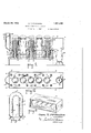
- Fig. 1 is a vertical sectional view of an apparatus containing my improvement
- Fig. 2 is a horizontal sectional view of the same corresponding to the line 2-2 of Fig. 1
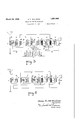
- Fig. 3 is a perspective view partly in section 0 a modified form of apparatus
- Fig. i is a sec tional view through one of the tubes showing the essential structure both of the detector, the amplifier, and the potential tuber
- Fig. 5 is a diagram of the connections of the device shown in Fig. 1
- Fig. 6 is a diagram of the connections of the device shown in Fig. 3.
- ode consists of a layer of some substance which readily emits electrons under the influence of radiant energy this material being plated directly on the glass wall of the tube which is itself suitthe tube wall; the anode is also, preferably, formed of a thin layer of conductive material plated on glass; and the tube is preferably made of a new and peculiar shape which is specially adapted to the mode of potential production herein described.
- the tube comprises a globe of glass as shown in Fig. 4 with a cylindrical side wall 1 reduced at one end to the exhausting stem which is ultimately sealed ofi leaving a point 2.
- Hermetically fastened to the oppositeend of the side wall is the flange 4 of the flare which has a cylindrical ably plated upon f as indicated at the portion 46 of the 1927.
- the cathzirconium In these tubes the cathzirconium,
- the walled'hollow body 5 projecting into the globe and spaced from and concentric with the outer wall and extending nearly to the closed end thereof.
- the flange is sealed to the outer wall at in the usual manner custom ary in making incandescent lamps, and the two parts thus assembled define a chamber which is everywhere annular except near the point 2.
- the inner surface of the wall 1 is rendered conducting by the deposit thereon of a layer 9 of a suitable substance, while the adjacent surface of the body 5 is likewise provided with the layer 8 of suitable conduct ing substance.
- These layers may consist of the same or difi'erent substances, and may both be electronically emissive. or only one of the same may be emissive under given conditions.
- tubes wherein the outer layer 9 constitutes the cathode and the innerlayer 8 the anode It is possible to make both these layers of the same electronically emissive metal and maintain a sufiicient temperature diiferent 'between the two to insure an adequate potential generation; it is preferable, however, in most cases, to employ different substances for the two walls which shall diifer in their electronic emissivity ture so as to produce the desired operation.
- the emitting material may consist of any suitable substance for that purpose, for example silver, thorium, potassium, sodium, caesium or any of the alkali earth metals; the anode may consist of any of these, or in addition any other conductive substance either plated upon the body 5 or otherwise even at the same tempera-.
- Figs. 1 and 2 a rectangular metal box comprising top 11, sides 12-12 and ends 13, 13 flanged at 14 for application to a horizontal bottom plate 15 in such wise that one end shall project therebeyond.
- Supporting this bottom plate is a block 16 formed with a plurality of vertical recesses 17 provided with sockets 18 adapted to receive the bases 19 with which the tubes are provided.
- the bottom plate 15 is formed with apertures 2020 registering with the recess 17 to permit the'tubes to rise into the body of the box.
- the overhanging end of the box is formed with an aperture 21 adapted to receive the chimney 22 of a kerosene lamp or other suitable heat source.
- the opposite end is here shown as provided with a chimney 23 and damper 24.
- a rod 26 of copper or other heat conductive metal is located inside each of the bodies 5, 5, its outer end being connected to a heat dissipating plate 27.
- a rod 26 of copper or other heat conductive metal is located inside each of the bodies 5, 5, its outer end being connected to a heat dissipating plate 27.
- Many other expedients can be used.
- each of the tubes heretofore described as employed in this set is provided with three elements, the cathode 9, anode 8 and grid 10 heretofore described. With these can also be used some plain potential tubes, if desired for the purpose of increasing the power of the set, said tubes being here indicated at 28 and made of smaller size than the first described tubes and supported in the top 10 with their exterior surfaces receiving the maximum heat while their interiors are cooled by external convection. Any desired system of connections can be employed, the diagram in Fig. 5 being merely one of many circuits which can be employed.
- 3O denotes an aerial or antenna inductively coupled at 31 through a variable condenser 32 with a tube A of the type herein described.
- This tube is here shown as coupled to form a radio frequency amplifier, and its anode 8 is connected-through an inductive coupler 33 and variable condenser 34 to a second tube B also serving as a radio amplifier, having its anode 8 connected via inductive coupler 35 and variable condenser 36 to a third tube 0 here arranged as a detector.
- the anode 8 of tube C is connected through an inductive coupler 37 with a fourth tube D here arranged as an audio f equency amplifier.
- the anode 8 of tube D is connected through the inductive coupler 38 with a further tube E, also acting as an audio frequency amplifier.
- the anode 8 of tube E is connected to the sound producer 40.
- thermo-cells As a B battery I have shown a series F F of the thermo-cells hereinbefore described, connected together in series.
- the negative lead 41 is connected to the cathode 9 of tubes A, C, D, and E; the positive terminal 42 is connected to the sound producer 40.
- Intermediate taps 4.3 and 44 can be connected to the circuit at different points in any desired manner. I have shown for illustrative purposes a composite circuit which is obviously capable of many modifications, although itself very successful.
- Fig. 3 wherein 50 denotes a rectangular metal box provided with a plurality of tubes of the type illustrated in Fig. 4 hereof, all connected together according to some suitable system as for example the circuit illustrated in Fig. 6, and adapted to operate merely by being subjected to action of a suitable heat source.
- each tube is itself a source of potential, an external current can be produced and governed without external aid, suflicient for many purposes but obviously not so strong as one externally supplemented.
- the reference characters of Fig. 6 are the same as employed in Fig. 5 it is not believed necessarry to repeat the description of the circuit.
- the electrical and magnetic couplings and the sound producer must be designed with reference to the usein question, namely a comparatively small potential and low resistance.
- the apparatus can with small modifications be adapted for use with a coal stove, wood fire, steam radiator, or even intense sunlight, and because of the many changes in detail which are possible I do not limit myself in any wise except as recited in the annexed claims.
- Radio reception apparatus comprising, in combination, a plurality of evacuated tubes each having an anode and cathode, said cathode being of a material which will produce a potential between said anode and cathode by electronic expulsion when said cathode is subjected to a source of heat, a source of heat external to said tubes, control electrodes in. certain at least of said tubes, and connections between the various electrodes of said tubes, said connections including capacities, induc tances and terminals provisions.
- Radio reception apparatus comprising, in combination, a pluraht of evacuated tubes each having an anode an cathode, said cathode being of a material which will produce a potential between said anode and cathode by electronic expulsion when said cathode is subjected to a source of heat, a source of heat external to said tubes, control electrodes in certain of said tubes, the remaining tubes being devoid of control electrodes, connections between the tubes which contain control electrodes for the detection and amplification of radio signals, and connections between those tubes which do not contain control electrodes and the remaining tubes for the production of potential.
- Radio reception apparatus comprising, in combination, a plurallty of evacuated tubes each having an anode and cathode, said cathode being of a material which will produce a potential between said anode and cathode by electronic expulsion when said cathode is subjected to a source of heat, a source of heat externalto said tubes, and circuit connections between the elements of said tubes.
- Radio reception apparatus comprising, in combination, a plurality of evacuated tubes each having an anode and cathode adapted to produce a potential by electronic expulsion when subjected to a source of heat, a metallic box having apertures in its walls, means for supporting said tubes with their cathode containing parts inside the box and their anode containing parts in communication with the exterior of the box, and means for supplying heat to the interior of said box.
- Radio reception apparatus comprising,
- each comprising concentric glass walls defining an annular chamber having theanode and cathode plated on opposed inner surfaces, a metallic box having apertures in its wall,
- Radio reception apparatus comprising,-
- a plurality of evacuated tubes each comprising concentric glass walls defining an annular chamber having the anode and cathode plated on opposed inner surfaces, a metallic box having apertures in its wall, means for heating the air inside said box, and means for supporting said tubes in said apertures with their cathode-carrying walls in contact with the internal atmosphere and their anode-carrying walls opening outward- 1y to the outer atmosphere, the cathode comprising material which emits electrons when heated.
- Radio reception apparatus comprising, in comblnatlon, a plurality of evacuated tubes, each comprising concentnc glass walls defining an annular chamber having the an ode and cathode plated on opposed inner sur faces, a metallicbox having apertures in wall, means for heating the air inside said box, and means for s porting said tubes in said apertures with t eir' cathode-carrying walls in contact with the-internal atmosphere and their anode-carrying walls opening outwardly to the outer atmosphere, the cathode comprising material which emits electrons when heated, and means for abstracting heat from the anode-carrying walls.
- Radio reception apparatus comprising a supporting device, and electron tubes mounted therein having anodes and cathodes, each cathode coated with a substance which is adapted to emit electrons when heated and each anode facing the corresponding cathode at a short distance, and means tor a%ply1ng external heat to said tubes.
- adio reception apparatus comprising a support having sockets, a plurality of electron tubes carried by said sockets, said tubes having cathodes adapted to emit electrons when heated, anodes and control electrodes also located in said tubes, a box adapted to receive the cathode-containing part of said iubes, and means for heating the fluid'in said 10.
- Radio reception apparatus comprising a plurality of electronic tubes each containmg anode, cathode, and control electrode,
- Radio reception apparatus comprising, in combination, a plurality of evacuated tubes each having an anode and cathode adapted to produce a potential by electronic expulsion when subjected to a source oi heat, a support for said tubes, means for heating the oathode-containing partsof said tubes, and means for shielding against heating the anode-consignature.
- Radio reception apparatus comprising, in combination, a plurality of evacuated tubes, each comprising concentric glass walls defining an annular chamber having the anode and cathode plated on opposed inner surfaces, a box having apertures in its walls, means for supporting said tubes with their inner walls presented to said apertures, and a metallic conducting member in each inner wall and projecting outside said box.
Landscapes
- Engineering & Computer Science (AREA)
- Computer Networks & Wireless Communication (AREA)
- Signal Processing (AREA)
- Vessels, Lead-In Wires, Accessory Apparatuses For Cathode-Ray Tubes (AREA)
Description
March 29, 1932. o. 'r. M ILVAINE RADIO RECEPTION APPARATUS Sheets-Sheet Filed Oct. 7, 192'! Oran T. A2 Iloaine Attornegs March 29, 1932. o, MOILVAINE RADIO RECEPTION APPARATUS 2 Sheets-Sheet Filed Oct. 7, 1927 Oran 'T: M Ilva-l-ne I Inventor Attornegs or on a conducting layer Patented Mar. 29, 1932 v UNITED STATES PATENT OFFICE ORAN '1. KCILVAINE, 01' EAST GLEVELND, OHIO, ASSTGNOR T0 MGIL'VAINE PATENT conrom'rron,
OF ST. CHARLES, ILLINOIS, L. (K'IB-POIBA'JPION OF DELAWARE RADIO RECEPTION APPABA T'FS Application filed October 7, 1927. Serial No. 224,608.
This invention relates to radio apparatus and has for its object the provision of new, 1mproved, and simplified apparatus for the reception of radio signals; the provision-of radio reception apparatus which shall be operative without external current or potential supply; the provision of a tube type of radio reception apparatus which shall be adapted to detect and amplify signals merely under the influence of-heat; while further objects and advantages of the invention will become apparent as the description proceeds.
In the drawings I have shown certain physical embodiments of my invention, although it will be understood that the same are intended to be merely illustrative and not limiting. Fig. 1 is a vertical sectional view of an apparatus containing my improvement; Fig. 2 is a horizontal sectional view of the same corresponding to the line 2-2 of Fig. 1; Fig. 3 is a perspective view partly in section 0 a modified form of apparatus; Fig. i is a sec tional view through one of the tubes showing the essential structure both of the detector, the amplifier, and the potential tuber Fig. 5 is a diagram of the connections of the device shown in Fig. 1; and Fig. 6 is a diagram of the connections of the device shown in Fig. 3. The apparatus herein described depends upon the use of tubes of the general type set forth in my application SeriaLNo. 209,281, filed July 29, ode consists of a layer of some substance which readily emits electrons under the influence of radiant energy this material being plated directly on the glass wall of the tube which is itself suitthe tube wall; the anode is also, preferably, formed of a thin layer of conductive material plated on glass; and the tube is preferably made of a new and peculiar shape which is specially adapted to the mode of potential production herein described.
In its preferred form the tube comprises a globe of glass as shown in Fig. 4 with a cylindrical side wall 1 reduced at one end to the exhausting stem which is ultimately sealed ofi leaving a point 2. Hermetically fastened to the oppositeend of the side wall is the flange 4 of the flare which has a cylindrical ably plated upon f as indicated at the portion 46 of the 1927. In these tubes the cathzirconium,
walled'hollow body 5 projecting into the globe and spaced from and concentric with the outer wall and extending nearly to the closed end thereof. The flange is sealed to the outer wall at in the usual manner custom ary in making incandescent lamps, and the two parts thus assembled define a chamber which is everywhere annular except near the point 2. In the preferre form of my invention the inner surface of the wall 1 is rendered conducting by the deposit thereon of a layer 9 of a suitable substance, while the adjacent surface of the body 5 is likewise provided with the layer 8 of suitable conduct ing substance. These layers may consist of the same or difi'erent substances, and may both be electronically emissive. or only one of the same may be emissive under given conditions. It is necessary that some discontinuity be provided between the two surfaces globe. In the case of a tube used merely for the production of potential no'intermediate element or grid is employed. but in case of a tube employed for detecting or amplifying signals a grid element 10 is interposed between the layers 8 and 9 but out of contact with both of the same. The three elements are connected to terminal wires which lead downwardly through the seal 45.
For a set of shown it is considered preferable to employ tubes wherein the outer layer 9 constitutes the cathode and the innerlayer 8 the anode. It is possible to make both these layers of the same electronically emissive metal and maintain a sufiicient temperature diiferent 'between the two to insure an adequate potential generation; it is preferable, however, in most cases, to employ different substances for the two walls which shall diifer in their electronic emissivity ture so as to produce the desired operation. The emitting material may consist of any suitable substance for that purpose, for example silver, thorium, potassium, sodium, caesium or any of the alkali earth metals; the anode may consist of any of these, or in addition any other conductive substance either plated upon the body 5 or otherwise even at the same tempera-.
supported in facial relation with the layer 9, so that when the latter is sufiiciently heated a part of the electrons expelled therefrom shall be able to cross the gap and electrify the layer 8, whereupon the latter, either by being of a less emissive metal or by being maintained at a lower temperature, can become relieved bf its charge only by current flow through an external circuit.
As a convenient and very simple mode of utilizing these tubes in the formof a radio set, I have illustrated in Figs. 1 and 2 a rectangular metal box comprising top 11, sides 12-12 and ends 13, 13 flanged at 14 for application to a horizontal bottom plate 15 in such wise that one end shall project therebeyond. Supporting this bottom plate is a block 16 formed with a plurality of vertical recesses 17 provided with sockets 18 adapted to receive the bases 19 with which the tubes are provided. The bottom plate 15 is formed with apertures 2020 registering with the recess 17 to permit the'tubes to rise into the body of the box. The overhanging end of the box is formed with an aperture 21 adapted to receive the chimney 22 of a kerosene lamp or other suitable heat source. The opposite end is here shown as provided with a chimney 23 and damper 24.
In case it be desired to maintain a temperature difference between the interior and exterior of the tubes, such an expedient can be employed as is illustrated in Fig. l, wherein a rod 26 of copper or other heat conductive metal is located inside each of the bodies 5, 5, its outer end being connected to a heat dissipating plate 27. Many other expedients can be used.
Each of the tubes heretofore described as employed in this set is provided with three elements, the cathode 9, anode 8 and grid 10 heretofore described. With these can also be used some plain potential tubes, if desired for the purpose of increasing the power of the set, said tubes being here indicated at 28 and made of smaller size than the first described tubes and supported in the top 10 with their exterior surfaces receiving the maximum heat while their interiors are cooled by external convection. Any desired system of connections can be employed, the diagram in Fig. 5 being merely one of many circuits which can be employed.
3O denotes an aerial or antenna inductively coupled at 31 through a variable condenser 32 with a tube A of the type herein described. This tube is here shown as coupled to form a radio frequency amplifier, and its anode 8 is connected-through an inductive coupler 33 and variable condenser 34 to a second tube B also serving as a radio amplifier, having its anode 8 connected via inductive coupler 35 and variable condenser 36 to a third tube 0 here arranged as a detector. The anode 8 of tube C is connected through an inductive coupler 37 with a fourth tube D here arranged as an audio f equency amplifier. The anode 8 of tube D is connected through the inductive coupler 38 with a further tube E, also acting as an audio frequency amplifier. The anode 8 of tube E is connected to the sound producer 40.
As a B battery I have shown a series F F of the thermo-cells hereinbefore described, connected together in series. The negative lead 41 is connected to the cathode 9 of tubes A, C, D, and E; the positive terminal 42 is connected to the sound producer 40. Intermediate taps 4.3 and 44 can be connected to the circuit at different points in any desired manner. I have shown for illustrative purposes a composite circuit which is obviously capable of many modifications, although itself very successful.
many cases it is sufficient to use the three element tubes without potential devices of any kind, in which case the parts can still further be simplified as illustrated for example in Fig. 3, wherein 50 denotes a rectangular metal box provided with a plurality of tubes of the type illustrated in Fig. 4 hereof, all connected together according to some suitable system as for example the circuit illustrated in Fig. 6, and adapted to operate merely by being subjected to action of a suitable heat source. Inasmuch as each tube is itself a source of potential, an external current can be produced and governed without external aid, suflicient for many purposes but obviously not so strong as one externally supplemented. Inasmuch as the reference characters of Fig. 6 are the same as employed in Fig. 5 it is not believed necessarry to repeat the description of the circuit. Of course it will be understood that the electrical and magnetic couplings and the sound producer must be designed with reference to the usein question, namely a comparatively small potential and low resistance.
The apparatus can with small modifications be adapted for use with a coal stove, wood fire, steam radiator, or even intense sunlight, and because of the many changes in detail which are possible I do not limit myself in any wise except as recited in the annexed claims.
Having claim is: p v
1. Radio reception apparatus comprising, in combination, a plurality of evacuated tubes each having an anode and cathode, said cathode being of a material which will produce a potential between said anode and cathode by electronic expulsion when said cathode is subjected to a source of heat, a source of heat external to said tubes, control electrodes in. certain at least of said tubes, and connections between the various electrodes of said tubes, said connections including capacities, induc tances and terminals provisions.
thus described my invention what 2. Radio reception apparatus comprising, in combination, a pluraht of evacuated tubes each having an anode an cathode, said cathode being of a material which will produce a potential between said anode and cathode by electronic expulsion when said cathode is subjected to a source of heat, a source of heat external to said tubes, control electrodes in certain of said tubes, the remaining tubes being devoid of control electrodes, connections between the tubes which contain control electrodes for the detection and amplification of radio signals, and connections between those tubes which do not contain control electrodes and the remaining tubes for the production of potential.
3. Radio reception apparatus comprising, in combination, a plurallty of evacuated tubes each having an anode and cathode, said cathode being of a material which will produce a potential between said anode and cathode by electronic expulsion when said cathode is subjected to a source of heat, a source of heat externalto said tubes, and circuit connections between the elements of said tubes.
4. Radio reception apparatus comprising, in combination, a plurality of evacuated tubes each having an anode and cathode adapted to produce a potential by electronic expulsion when subjected to a source of heat, a metallic box having apertures in its walls, means for supporting said tubes with their cathode containing parts inside the box and their anode containing parts in communication with the exterior of the box, and means for supplying heat to the interior of said box.
5. Radio reception apparatus comprising,
- in combination, a plurality of evacuated tubes,
' communication, one with the each comprising concentric glass walls defining an annular chamber having theanode and cathode plated on opposed inner surfaces, a metallic box having apertures in its wall,
and means for supporting said tubes in saidapertures with their inner and outer walls in interior and the other with the exterior of the box.
6. Radio reception apparatus comprising,-
in combination, a plurality of evacuated tubes, each comprising concentric glass walls defining an annular chamber having the anode and cathode plated on opposed inner surfaces, a metallic box having apertures in its wall, means for heating the air inside said box, and means for supporting said tubes in said apertures with their cathode-carrying walls in contact with the internal atmosphere and their anode-carrying walls opening outward- 1y to the outer atmosphere, the cathode comprising material which emits electrons when heated.
7. Radio reception apparatus comprising, in comblnatlon, a plurality of evacuated tubes, each comprising concentnc glass walls defining an annular chamber having the an ode and cathode plated on opposed inner sur faces, a metallicbox having apertures in wall, means for heating the air inside said box, and means for s porting said tubes in said apertures with t eir' cathode-carrying walls in contact with the-internal atmosphere and their anode-carrying walls opening outwardly to the outer atmosphere, the cathode comprising material which emits electrons when heated, and means for abstracting heat from the anode-carrying walls.
8. Radio reception apparatus comprising a supporting device, and electron tubes mounted therein having anodes and cathodes, each cathode coated with a substance which is adapted to emit electrons when heated and each anode facing the corresponding cathode at a short distance, and means tor a%ply1ng external heat to said tubes.
9. adio reception apparatus comprising a support having sockets, a plurality of electron tubes carried by said sockets, said tubes having cathodes adapted to emit electrons when heated, anodes and control electrodes also located in said tubes, a box adapted to receive the cathode-containing part of said iubes, and means for heating the fluid'in said 10. Radio reception apparatus comprising a plurality of electronic tubes each containmg anode, cathode, and control electrode,
and other electronic tubes each containing an tubes each having an anode and cathode adapted to produce a potential by electronic expulsion when subjected to a source of heat, a box having apertures in its walls, means for supporting said tubes with their anodeand cathode-containing parts in communication, one with the interior and the other with the exterior of the box, and means for producing a difference of temperature inside and outside said box.
12. Radio reception apparatus comprising, in combination, a plurality of evacuated tubes each having an anode and cathode adapted to produce a potential by electronic expulsion when subjected to a source oi heat, a support for said tubes, means for heating the oathode-containing partsof said tubes, and means for shielding against heating the anode-consignature.
faces, and a metallic member having projectiogs adapted to enter the inner walls of said tu s.
14. Radio reception apparatus comprising, in combination, a plurality of evacuated tubes, each comprising concentric glass walls defining an annular chamber having the anode and cathode plated on opposed inner surfaces, a box having apertures in its walls, means for supporting said tubes with their inner walls presented to said apertures, and a metallic conducting member in each inner wall and projecting outside said box.
In testimony whereof I hereunto aflix my ORAN T. McILVAINE.
Priority Applications (1)
| Application Number | Priority Date | Filing Date | Title |
|---|---|---|---|
| US224603A US1851440A (en) | 1927-10-07 | 1927-10-07 | Radio reception apparatus |
Applications Claiming Priority (1)
| Application Number | Priority Date | Filing Date | Title |
|---|---|---|---|
| US224603A US1851440A (en) | 1927-10-07 | 1927-10-07 | Radio reception apparatus |
Publications (1)
| Publication Number | Publication Date |
|---|---|
| US1851440A true US1851440A (en) | 1932-03-29 |
Family
ID=22841374
Family Applications (1)
| Application Number | Title | Priority Date | Filing Date |
|---|---|---|---|
| US224603A Expired - Lifetime US1851440A (en) | 1927-10-07 | 1927-10-07 | Radio reception apparatus |
Country Status (1)
| Country | Link |
|---|---|
| US (1) | US1851440A (en) |
Cited By (1)
| Publication number | Priority date | Publication date | Assignee | Title |
|---|---|---|---|---|
| US2445754A (en) * | 1943-06-19 | 1948-07-27 | Melvin D Baller | Vacuum tube |
-
1927
- 1927-10-07 US US224603A patent/US1851440A/en not_active Expired - Lifetime
Cited By (1)
| Publication number | Priority date | Publication date | Assignee | Title |
|---|---|---|---|---|
| US2445754A (en) * | 1943-06-19 | 1948-07-27 | Melvin D Baller | Vacuum tube |
Similar Documents
| Publication | Publication Date | Title |
|---|---|---|
| US1907507A (en) | Electron discharge device | |
| US2722624A (en) | Electron tube | |
| US1965849A (en) | Electronic tube | |
| US1851440A (en) | Radio reception apparatus | |
| US2765421A (en) | Electron discharge devices | |
| US1886705A (en) | Indirect electron excitation for thermionic vacuum tubes | |
| US2688707A (en) | Electron tube structure | |
| US2092804A (en) | Screen grid electron discharge tube | |
| US2206954A (en) | Electron discharge device | |
| US1639805A (en) | Radio apparatus | |
| US2227030A (en) | Electron amplifier | |
| US2667593A (en) | Electron tube | |
| US2898501A (en) | Getters for electron tubes | |
| US2447719A (en) | Electron tube | |
| US2822508A (en) | Remote lighting system | |
| US3124710A (en) | X-ray tubes | |
| US2184910A (en) | Cold cathode electron discharge tube | |
| US2884553A (en) | Modular electron-discharge tube | |
| US2975313A (en) | Metal x-ray image tube | |
| US1945979A (en) | Electron discharge tube | |
| US2431097A (en) | Electron discharge device | |
| US2005257A (en) | Vacuum tube grid | |
| US1871537A (en) | Electron discharge device | |
| US1677316A (en) | Photoelectric cell | |
| US1744653A (en) | Audio and high frequency amplifying tube |