US1851437A - Method of making trolley ears - Google Patents
Method of making trolley ears Download PDFInfo
- Publication number
- US1851437A US1851437A US487795A US48779530A US1851437A US 1851437 A US1851437 A US 1851437A US 487795 A US487795 A US 487795A US 48779530 A US48779530 A US 48779530A US 1851437 A US1851437 A US 1851437A
- Authority
- US
- United States
- Prior art keywords
- ear
- lips
- groove
- boss
- trolley
- Prior art date
- Legal status (The legal status is an assumption and is not a legal conclusion. Google has not performed a legal analysis and makes no representation as to the accuracy of the status listed.)
- Expired - Lifetime
Links
- 238000004519 manufacturing process Methods 0.000 title description 9
- 210000005069 ears Anatomy 0.000 title description 3
- 239000002184 metal Substances 0.000 description 19
- 229910052751 metal Inorganic materials 0.000 description 19
- 238000000034 method Methods 0.000 description 14
- 238000005520 cutting process Methods 0.000 description 8
- 238000005266 casting Methods 0.000 description 6
- 238000003754 machining Methods 0.000 description 6
- 238000010276 construction Methods 0.000 description 4
- 238000003801 milling Methods 0.000 description 4
- 229910001369 Brass Inorganic materials 0.000 description 2
- 239000010951 brass Substances 0.000 description 2
- 229910000906 Bronze Inorganic materials 0.000 description 1
- RYGMFSIKBFXOCR-UHFFFAOYSA-N Copper Chemical compound [Cu] RYGMFSIKBFXOCR-UHFFFAOYSA-N 0.000 description 1
- 239000010974 bronze Substances 0.000 description 1
- 239000004020 conductor Substances 0.000 description 1
- 229910052802 copper Inorganic materials 0.000 description 1
- 239000010949 copper Substances 0.000 description 1
- KUNSUQLRTQLHQQ-UHFFFAOYSA-N copper tin Chemical compound [Cu].[Sn] KUNSUQLRTQLHQQ-UHFFFAOYSA-N 0.000 description 1
- 238000005242 forging Methods 0.000 description 1
- 230000009191 jumping Effects 0.000 description 1
- 238000012986 modification Methods 0.000 description 1
- 230000004048 modification Effects 0.000 description 1
- 239000007787 solid Substances 0.000 description 1
Images
Classifications
-
- B—PERFORMING OPERATIONS; TRANSPORTING
- B21—MECHANICAL METAL-WORKING WITHOUT ESSENTIALLY REMOVING MATERIAL; PUNCHING METAL
- B21D—WORKING OR PROCESSING OF SHEET METAL OR METAL TUBES, RODS OR PROFILES WITHOUT ESSENTIALLY REMOVING MATERIAL; PUNCHING METAL
- B21D53/00—Making other particular articles
-
- B—PERFORMING OPERATIONS; TRANSPORTING
- B60—VEHICLES IN GENERAL
- B60M—POWER SUPPLY LINES, AND DEVICES ALONG RAILS, FOR ELECTRICALLY- PROPELLED VEHICLES
- B60M1/00—Power supply lines for contact with collector on vehicle
- B60M1/12—Trolley lines; Accessories therefor
- B60M1/20—Arrangements for supporting or suspending trolley wires, e.g. from buildings
- B60M1/24—Clamps; Splicers; Anchor tips
-
- Y—GENERAL TAGGING OF NEW TECHNOLOGICAL DEVELOPMENTS; GENERAL TAGGING OF CROSS-SECTIONAL TECHNOLOGIES SPANNING OVER SEVERAL SECTIONS OF THE IPC; TECHNICAL SUBJECTS COVERED BY FORMER USPC CROSS-REFERENCE ART COLLECTIONS [XRACs] AND DIGESTS
- Y10—TECHNICAL SUBJECTS COVERED BY FORMER USPC
- Y10T—TECHNICAL SUBJECTS COVERED BY FORMER US CLASSIFICATION
- Y10T29/00—Metal working
- Y10T29/49—Method of mechanical manufacture
- Y10T29/49002—Electrical device making
- Y10T29/49227—Insulator making
Definitions
- My invention deals with the construction and method of manufacturing a trolley wire support and known as a trolley ear of the clinch type.
- the object of my invention is to provide a new and novel support for a trolley wire in which the lips may be clinched about the wire and after clinching will permit the moving current collector to pass from the wire to the ear and from the ear to the wire with as little interference as possible.
- a further object of my invention is to provide a process of manufacturing the car which will be simple and economical.
- My invention resides in the new and novel construction and the steps involved in the process of producing the device.
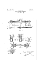
- Fig. 1 is a side view of my invention.
- Fig. 2 is a bottom view of my invention ihogving a trolley wire in position in the right
- Fig. 3 is an end View of Fig. 1.
- Figs. 4 and 5 are sectional views on the line H and 55 of Fig. 1.
- FIGs. 6 and 7 show schematically the manner in which certain features of my invention are produced.
- I have an elongated body member which is provided with an elongated grooved part 1 comprising a pair of downwardly extending lips 2 forming a groove 3.
- a boss part 4 having a threaded recess 5 for attachment to an overhead support.
- I project ribs 6 from opposite sides of the boss and extending along the upper surface of the part 1.
- the part 1. the boss 4 and the ribs 6 are integrally united to each other, in fact, they are formed as a tion A and the overall width of section A of part 1 is substantiallyuniform.
- the lips of section A are comparatively heavy or thick in order to allow as'much metal for wear as possible and yet be properly bent or peened about the conductor. It will be recognized that since the trolley collector slides or rolls along the lower surface of the ear asfinally installed that there is considerable wear to the lower surface of the lips when bent into position and therefore it is desirable that such lips should be made as heavy as possible.”
- each section' B may be groove and higher cost.
- the machiningof the groove may be done upon a standard milling machine having proper clamping arrangements to hold the ear to the machine or upon a grinder.
- the ear is now ready to have the outer surface of the lips'at sections B tapered and this may be accomplished by forcing the ear between rotating milling cutters as shown in Figs. 6 and 7
- the axes 8 of the milling cutters are angularly disposed to each other to give the proper degree of taper to the sides of the ear.
- the cutters 9 both revolve in the same direction and as indicated by the arrowwhile the cutters 10 each revolve in the same direction, but opposite to that of the cutters 9.
- the milled outer surfaces of the portion B are in vertical, planes indicated by the lines D as shown in-Fig. 5, but such planes are angularly disposed in a horizontal direction indicated by the lines DD in Fig. 2.
- the angular relation of the faces 1170f section B may be varied by changing the angularity of the cutting faces of the millers 9 and 10, that is, the cutters may be so arranged as to taper the faces 11 such that the lips will be thinner at the lower edge than at the upper end that is, taper the faces 11 in both vertical and horizontal directions. 7
- a form member 12 which is an elongated bar having a portion 18 which exactly fits the groove and prevents the lips being bent inwardly during the milling operation. "I have shown teeth 15 on one miller, but all the millersare arranged likewise.
- the lips of section B at the right end when bent upon the trolley wire T shows a V shaped spacing 14 between the edges of the lips and this also assists in easy passing of the current collector onto and off the ear and this V shaped opening 14 is brought about by'varying the height of the lips of section B which in turn varies'the depth of the groove along section B as indicated by the lines E and F'in Fig. 1.
- Figs. 3, 4 and 5' it will be noted that the curved or seat portion of the groove 3 is shown as coinciding with the line G and thatthe maximum depth of groove is shown in Fig. 4 as H and in Fig. 5 as J" which is less than the depth H and that the depth of the groove adjacent the end of the ear is shown in F ig. 3 as 'K. 7
- the ear may be formed up of copper, brass or bronze as by a drop forging and then have the boss 4 ⁇ and part 1 machined as described.
- the ear may be formed by having the boss 4 and ribs 6 cast integral and the part 1 formed up of sheet metal of uniform thickness and welded or otherwise secured to the ribs and boss and the ends of the lips would then be tapered as above described but the groove will probably not require machining as it would be formed to size.
- the order of machining the boss with respect to the groove and lips may be varied as it is not necessary to first machine the boss but I prefer to machine the groove before tapering the lips.
- I claim 1 The process of manufacturing a trolley wire support comprising the steps of forming a body of metal having a grooved longi tudinal part and a supporting part 'by casting molten metal in a mold cavity of proper shape, then threading the supporting part and smooth finishing the surface of the groove to produce a groove of uniform width, then passing the end portions of the longitudinal part between rotating cutters to smooth the outer surfaces of the longitudinal part for a predetermined distance back from each end and giving the said surfaces a tapered relation to each other from the ends of the longitudinal part towards the center to increase the thickness of the lips from substantially a knife edge at the ends.
- a trolley wire support comprising the steps of forming a body of metal having a grooved elongated-part and a supporting part by casting molten -metal ina mold cavity of predeterminedshape, then threading the supporting part andsmooth finishing the surface of the groove to produce a groove of uniform width, then passing the end portions of the elongated part alternately between rotating cutters t0 finishthe outersurfacesof the elongated part for a predetermined distance back from the ends of the elongated part towards the center .to increase the thickness of the lips from substantially a knife edge at the ends.
- a trolley ear comprising forming a metal body having a supporting member and an elongated part with depending lips forming a groove of uniform width and non-uniform depth, then machining the supporting member and subjecting first two side surfaces and then the other two side surfaces at the ends of the longitudinal part to a. rotating cutting action for a predetermined distance back from each end and giving the said surfaces a tapered relation to each other from the ends of the longitudinal part towards the center of the ear to increase the thickness of the lips from substantially a knife edge at the ends.
- the process of producing a trolley ear comprising the steps of forming a metal body having a supporting part and an elongated part secured together, machining the elongated part toform depending lips of uniform thickness and a wire receiving groove therebetween of uniform width to receive a trolley wire, threading the supporting part and subjecting opposite faces of one end and then the opposite faces of the other endto the cutting action spaced rotating metal removing means to remove metal from theouter surface of the lips for a predetermined distance from their ends towards the ear center and giving the said surfaces a tapered relation to each other from the ends of the elongated part towards the center to increase the thickness of the lip-s from substantially a knife edge at the ends.
- the process of producing a trolley ear comprising the steps of forming an elongated metal part with depending lips of uniform thickness providing a wire receiving groove therebetween and having also a supporting member, then removing metal from two side surfaces of the end portions by a rotating cutting action and then subjecting the other two surfaces to like action to finish the lips throughout substantially their entire height with a flat surface for a predetermined distance back from each end and taper the lips to increase the thickness of the lips from substantially a knife edge at the ends.
- the process of producing a trolley ear comprising the steps of forming a metal body having a supporting part and an elongated part, threading the boss, machining a groove in the elongated part by removing metal to receive a trolley wire and form lips and removing metal from the outside faces of the end portions of the elongated part by cutting action to smooth the outer surface ofthe elongated part for a predetermined distance back from the ends and give the said surfaces a tapered relation to each other from the ends ofthe longitudinal part towards the center to increase the thickness of the lips from a substantially a knife edge at the ends.
Landscapes
- Engineering & Computer Science (AREA)
- Mechanical Engineering (AREA)
- Current-Collector Devices For Electrically Propelled Vehicles (AREA)
Description
March 29, 1932. F. A. KLOHs METHOD OF MAKING TROLLEY EARS Filed Oct. 10. 1930 Inventor 1 M A. [Kw/15.
A tlor ne y Patented Mar. 29, 1932- UNITED s'm'rs mas since FRANK A. KLOHS, OF MANSFIELD; OHIO, ASSIGNOR TO THE OHIO BRASS COMPANY, OF
MANSFIELD, OHIO, A CORPORATION OF NEW JERSEY METHOD OF MAKING TBOLLEY E RS;
Application filed October 10, 1930. Serial No. 487,795.
My invention deals with the construction and method of manufacturing a trolley wire support and known as a trolley ear of the clinch type.
The object of my invention is to provide a new and novel support for a trolley wire in which the lips may be clinched about the wire and after clinching will permit the moving current collector to pass from the wire to the ear and from the ear to the wire with as little interference as possible.
A further object of my invention is to provide a process of manufacturing the car which will be simple and economical.
My invention resides in the new and novel construction and the steps involved in the process of producing the device.
In the drawings 2- Fig. 1 is a side view of my invention.
Fig. 2 is a bottom view of my invention ihogving a trolley wire in position in the right Fig. 3 is an end View of Fig. 1.
Figs. 4 and 5 are sectional views on the line H and 55 of Fig. 1.
Figs. 6 and 7 show schematically the manner in which certain features of my invention are produced.
It is quite desirable to provide ears of the clinch type for use in supporting a trolley wire which will have as long life as possible and which will not obstruct or interfere with the smooth and easy passage of the current collector in passing from the wire onto theear and vice versa. In order to secure these results I have found certain features of construction very desirable and which are set forth in this specification.
In. the embodiment of my invention I have an elongated body member which is provided with an elongated grooved part 1 comprising a pair of downwardly extending lips 2 forming a groove 3. Mounted upon the portion 1 is a boss part 4 having a threaded recess 5 for attachment to an overhead support. To stiffen the part 1 and also to better secure the boss 4 thereto. I project ribs 6 from opposite sides of the boss and extending along the upper surface of the part 1. The part 1. the boss 4 and the ribs 6 are integrally united to each other, in fact, they are formed as a tion A and the overall width of section A of part 1 is substantiallyuniform. The lips of section A are comparatively heavy or thick in order to allow as'much metal for wear as possible and yet be properly bent or peened about the conductor. It will be recognized that since the trolley collector slides or rolls along the lower surface of the ear asfinally installed that there is considerable wear to the lower surface of the lips when bent into position and therefore it is desirable that such lips should be made as heavy as possible."
Should the lips as constructed in section A be extended throughout the length of the ear, then it will be recognized thatdue to the thickness of the lipsand the ends of the ear considerable obstruction would be offered at the passage of the collector from the wire to the ear and this would cause a jumping of the moving collector; with considerable arcing, pounding and wearingv of the ear and collector and the same would be true when the collector left the ear at the opposite end. It has been customary in the past to bevel or grind the extreme end of the lips for a very short distanceback, but this does'not' eliminate or materially benefit the device unless the lips are made. relatively thin thereby materially reducing their life.
In order to maintain a maximum life or wear to the lips and to provide an easy and smooth passage of the current collector onto and ed the ear, I taper the part 1 for a considerable distance back from the end o-f'the ear and such taper starts with substantially a knife edge at the extreme end of the ear and the thickness of thelips will increase from such knife edge at the end of the ear to the full thickness of the lips at the adjacent end of section A. Each section' B may be groove and higher cost.
Therefore, I have so constructed the ear and have so processed the same that I am able to produce the desired article and economical manner.
I now prepare my patterns used in forming the molds in which the ear is cast, having uniform thickness of lips throughout the in a very length of the ear and such thickness will be 7 that of thefinished lips in section A plus an amount added for finishing the surface of the groove 3. The grooved portion 8, I also form in the mold by the use of what is termed a dry-sand core. By producing the ear in this manner the molten metal will run nicely to all parts of the cavity in the mold and fully fill the same out thus producing sound and complete castingswith substantially no losses. The part 1 may be cast solid if desired but this means slower machining to produce the Having produced the ear casting as described, I now taper portions B to provide the features set forth above.
First I machine the groove 3 to theproper V depth and width for the trolley wire and having a smooth and uniform surface such that when the lips of section A are peened or formed about the trolley wire the edges of the lips will meet or substantially so as shown at C Fig. 2. The machiningof the groove may be done upon a standard milling machine having proper clamping arrangements to hold the ear to the machine or upon a grinder.
The ear is now ready to have the outer surface of the lips'at sections B tapered and this may be accomplished by forcing the ear between rotating milling cutters as shown in Figs. 6 and 7 The axes 8 of the milling cutters are angularly disposed to each other to give the proper degree of taper to the sides of the ear. The cutters 9 both revolve in the same direction and as indicated by the arrowwhile the cutters 10 each revolve in the same direction, but opposite to that of the cutters 9. The milled outer surfaces of the portion B are in vertical, planes indicated by the lines D as shown in-Fig. 5, but such planes are angularly disposed in a horizontal direction indicated by the lines DD in Fig. 2. The angular relation of the faces 1170f section B may be varied by changing the angularity of the cutting faces of the millers 9 and 10, that is, the cutters may be so arranged as to taper the faces 11 such that the lips will be thinner at the lower edge than at the upper end that is, taper the faces 11 in both vertical and horizontal directions. 7
In positioning the ear between the millers 9 and'lO I insertin the groove a form member 12 which is an elongated bar having a portion 18 which exactly fits the groove and prevents the lips being bent inwardly during the milling operation. "I have shown teeth 15 on one miller, but all the millersare arranged likewise.
It will be recognized that the millers are to be properly mounted in a machine for maintaining them in' proper relation to each other and for giving themproper direction of rotation and having means for supporting, advancing and retracting, the ear with respect to the millers. I have not shown the machine in detail as I am not claiming the construction of the same in this application.
Referring to the drawings, it will be noted in Fig. 2 that the lips of section B at the right end when bent upon the trolley wire T shows a V shaped spacing 14 between the edges of the lips and this also assists in easy passing of the current collector onto and off the ear and this V shaped opening 14 is brought about by'varying the height of the lips of section B which in turn varies'the depth of the groove along section B as indicated by the lines E and F'in Fig. 1.
Referring to Figs. 3, 4 and 5' it will be noted that the curved or seat portion of the groove 3 is shown as coinciding with the line G and thatthe maximum depth of groove is shown in Fig. 4 as H and in Fig. 5 as J" which is less than the depth H and that the depth of the groove adjacent the end of the ear is shown in F ig. 3 as 'K. 7
It will be quite apparent that my process lac res
disclosed permits me to produce an ear which is very uniform and which is economical to manufacture 'due to the'small loss and which I I am able to produce in exacting dimensions and hence the results at that portion of the ear which a current collector first engages and which it last leaves will give a smooth and unobstructed passage of the collector onto and off the ear.
It is found in actual practice with the pres ent day high speeds dimensions make'a greatdifi'erence in the life of the ear, the wire and the collector andthe satisfaction which it gives in general, but by my method of manufacture I am able to produce an ear which meets all the requirements and my method also permits varying the results as for instance, the width of the part 1 throughout section A and also vary the width and taper along section B, also vary the length of sections A and B, also vary the V opening 14' and the. size of the groove 8. The general product will be a rough casting which has the groove 3 machined, also the faces 11 and the boss 4 drilled and threaded and likewise the face 12 of the boss 4 may be machined.
The ear may be formed up of copper, brass or bronze as by a drop forging and then have the boss 4} and part 1 machined as described. The ear may be formed by having the boss 4 and ribs 6 cast integral and the part 1 formed up of sheet metal of uniform thickness and welded or otherwise secured to the ribs and boss and the ends of the lips would then be tapered as above described but the groove will probably not require machining as it would be formed to size.
The order of machining the boss with respect to the groove and lips may be varied as it is not necessary to first machine the boss but I prefer to machine the groove before tapering the lips.
Modifications will suggest themselves, both in the structure and process herein disclosed and therefore I wish to be limited only by my claims.
I claim 1. The process of manufacturing a trolley wire support comprising the steps of forming a body of metal having a grooved longi tudinal part and a supporting part 'by casting molten metal in a mold cavity of proper shape, then threading the supporting part and smooth finishing the surface of the groove to produce a groove of uniform width, then passing the end portions of the longitudinal part between rotating cutters to smooth the outer surfaces of the longitudinal part for a predetermined distance back from each end and giving the said surfaces a tapered relation to each other from the ends of the longitudinal part towards the center to increase the thickness of the lips from substantially a knife edge at the ends.
2. The process of producing a trolley ear comprising forming a metal body by casting having a boss and an elongated part having depending lips forming a wire groove, then threading the boss and subjecting two outer surfaces of the lips simultaneously to a rotating cutting action and repeating this operation with the remaining two outer surfaces on the lips to remove the outer surface of the lips for a predetermined distance from their ends towards the ear center.
3. The process of producing a trolley ear comprising forming a metal body by casting metal in a mold having a boss and an elongated part with depending lips, then threading the boss and subjecting the outer surfaces of the ends of the elongated part simultaneously to a rotating cutting action to finish the side surfaces of the end portions of the elongated part, the motion of the cutting action being the same with respect to a given end.
l. The process of manufacturing a trolley wire support comprising the steps of forming a body of metal having a grooved elongated-part and a supporting part by casting molten -metal ina mold cavity of predeterminedshape, then threading the supporting part andsmooth finishing the surface of the groove to produce a groove of uniform width, then passing the end portions of the elongated part alternately between rotating cutters t0 finishthe outersurfacesof the elongated part for a predetermined distance back from the ends of the elongated part towards the center .to increase the thickness of the lips from substantially a knife edge at the ends.
5. The process of producing a trolley ear comprising forming a metal body having a supporting member and an elongated part with depending lips forming a groove of uniform width and non-uniform depth, then machining the supporting member and subjecting first two side surfaces and then the other two side surfaces at the ends of the longitudinal part to a. rotating cutting action for a predetermined distance back from each end and giving the said surfaces a tapered relation to each other from the ends of the longitudinal part towards the center of the ear to increase the thickness of the lips from substantially a knife edge at the ends.
6. The process of producing a trolley ear comprising the steps of forming a metal body having a supporting part and an elongated part secured together, machining the elongated part toform depending lips of uniform thickness and a wire receiving groove therebetween of uniform width to receive a trolley wire, threading the supporting part and subjecting opposite faces of one end and then the opposite faces of the other endto the cutting action spaced rotating metal removing means to remove metal from theouter surface of the lips for a predetermined distance from their ends towards the ear center and giving the said surfaces a tapered relation to each other from the ends of the elongated part towards the center to increase the thickness of the lip-s from substantially a knife edge at the ends.
7. The process of producing a trolley ear comprising the steps of forming an elongated metal part with depending lips of uniform thickness providing a wire receiving groove therebetween and having also a supporting member, then removing metal from two side surfaces of the end portions by a rotating cutting action and then subjecting the other two surfaces to like action to finish the lips throughout substantially their entire height with a flat surface for a predetermined distance back from each end and taper the lips to increase the thickness of the lips from substantially a knife edge at the ends.
8.. The process of producing a trolley ear comprising the steps of forming a metal body having a supporting part and an elongated part, threading the boss, machining a groove in the elongated part by removing metal to receive a trolley wire and form lips and removing metal from the outside faces of the end portions of the elongated part by cutting action to smooth the outer surface ofthe elongated part for a predetermined distance back from the ends and give the said surfaces a tapered relation to each other from the ends ofthe longitudinal part towards the center to increase the thickness of the lips from a substantially a knife edge at the ends.
In testimony whereof I afiix my signature.
FRANK A. KLOHS.
Priority Applications (1)
| Application Number | Priority Date | Filing Date | Title |
|---|---|---|---|
| US487795A US1851437A (en) | 1930-10-10 | 1930-10-10 | Method of making trolley ears |
Applications Claiming Priority (1)
| Application Number | Priority Date | Filing Date | Title |
|---|---|---|---|
| US487795A US1851437A (en) | 1930-10-10 | 1930-10-10 | Method of making trolley ears |
Publications (1)
| Publication Number | Publication Date |
|---|---|
| US1851437A true US1851437A (en) | 1932-03-29 |
Family
ID=23937143
Family Applications (1)
| Application Number | Title | Priority Date | Filing Date |
|---|---|---|---|
| US487795A Expired - Lifetime US1851437A (en) | 1930-10-10 | 1930-10-10 | Method of making trolley ears |
Country Status (1)
| Country | Link |
|---|---|
| US (1) | US1851437A (en) |
-
1930
- 1930-10-10 US US487795A patent/US1851437A/en not_active Expired - Lifetime
Similar Documents
| Publication | Publication Date | Title |
|---|---|---|
| US3677056A (en) | Multiple housing rolling mill | |
| CN110695286B (en) | Double-station die forging forming die and forming method for high manganese steel frog insert | |
| US1851437A (en) | Method of making trolley ears | |
| US2265129A (en) | Method of and apparatus for welding tubing or the like | |
| US2060859A (en) | Aerofoil wire | |
| US1903043A (en) | Method of cutting gears | |
| US1977556A (en) | Apparatus for finishing bolt heads and points | |
| US2135766A (en) | Method of producing metal grilles | |
| US1772876A (en) | Billet or blank suitable for the production of turbine blades | |
| EP2537605B1 (en) | Method for cross rolling of products in the shape of balls, in particular out of scrap railway rail heads | |
| US1699510A (en) | Metal-sharpening machine | |
| US2208572A (en) | Method and machine for finishing surfaces | |
| US958906A (en) | Ear for trolley-wires. | |
| US2370265A (en) | Apparatus for the manufacture of helical heat exchange fins | |
| US1783438A (en) | Process of making bearings | |
| US925028A (en) | Method of making ribbed plates. | |
| US1379717A (en) | Die | |
| RU2643286C1 (en) | Casting-rolling unit for producing copper cast billet | |
| CN113165058B (en) | Roll forming method for producing helical structures | |
| US1618791A (en) | Knife blank and method of making the same | |
| CN113941681A (en) | Forming method of titanium alloy forgings | |
| US1448001A (en) | Metal roll | |
| US1649929A (en) | Method of and apparatus for producing cap screws and the like | |
| US1917353A (en) | Method of producing beveled blades | |
| US754325A (en) | Wire-solder-rolling machine. |